In-depth Explanation: Terminology of Customizations for Touch Switch Sensors
Table of Contents
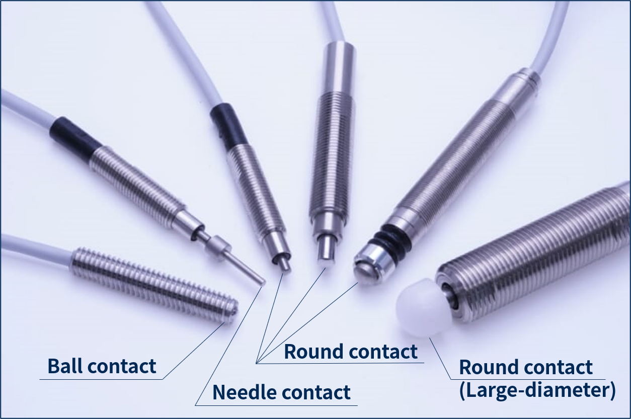
Contact Shape
METROL's touch switches can be customized to meet your application needs in terms of the shape and material of the contact-probes that touch the sensing workpiece.
How to Select Contact Shape
●Select by how the contact-probe will actually touch the workpiece.
There are three types of application methods: Straight-on, Sliding, and Angular.
●Select by the object that the contact touches for detection
If the object is curved, the contacts are recommended to be flat, and if the object is flat, curved contact-probes are recommended.
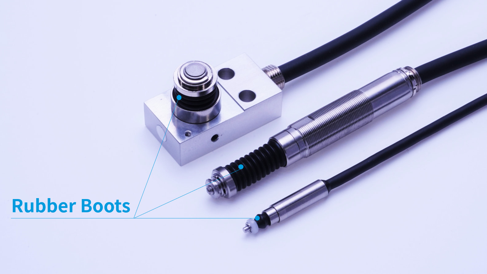
Boot Protection Cover
Boot Protection Cover
Sensors with an IP67 rating or higher are equipped with a "rubber boot" to prevent liquids and dust from entering the sensor.
The black bellows-shaped parts in the photo are the rubber boots.
Because the rubber boot is normally exposed, it can break in environments where sharp objects such as chips come in contact with the sensor, causing liquid or dust to enter the sensor.
In such cases, the "boot protection" option is recommended.
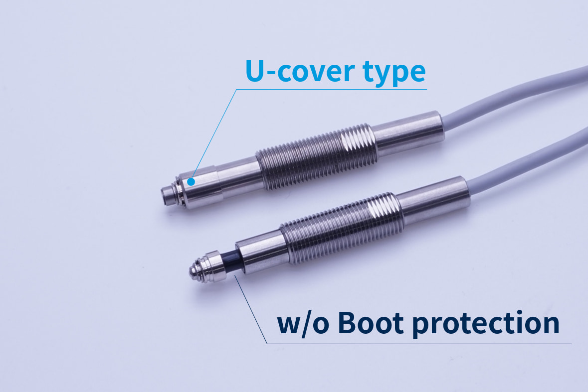
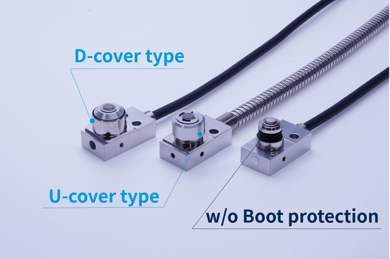
What is boot protection?
In environments where chips are produced, we always recommend the installation of boot protection because there are cases where the rubber boot is torn by chips.
There are two types of boot protection: "U-cover" and "D-cover".
How to Select Boot Protection
Please select according to the mounting direction of the sensor.
Boot protection: U-cover
Select this option when the sensor's contact surface is facing upward.
This protects the sensor from splashing liquid and chips from above.
Boot protection: D cover
Select the D cover when the contact surface of the sensor is facing downward.
When the sensor is used facing downwards, the U cover may cause a risk of sliding failure due to accumulation of liquid or chips on the sensor or sliding area between the contact and the cover.
CAUTIONS for Boot Protective Cover
When the sensor is used horizontally, be careful not to allow chips to accumulate between the cover and the sensor, or to prevent coolant from sticking. This may interfere with the ON/OFF operation of the sensor.
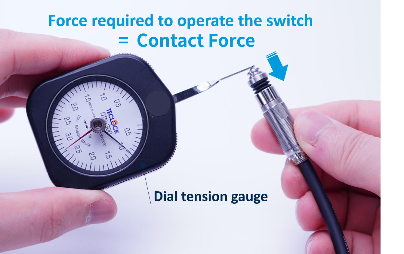
Contact force
Contact force refers to the force required to move the sensor from the free position to the signal operating point.
The contact force must not cause deformation (dents, deflections, scratches, and so forth) to the sensing object.
The more fragile or lightweight the workpiece, the more we recommend using low-touch force touch switches or non-contact sensors.
Transistor
NPN and PNP are available. Please check.
If you want to output NO in NC, we also have PhotoMOS (CL-1F) available. Output is achieved by installing it separately.
Three key features of the Transistor
Output current is increased to 100mA (resistive load)
Enables direct ON/OFF of relays (MAX 100mA).
Enables direct ON/OFF of relays (MAX 100mA).
Even if the positive and negative are connected in reverse, it will not break down.
Signal conversion circuit available
Normally open: NO → Normally closed: NC, NC → NO is possible.
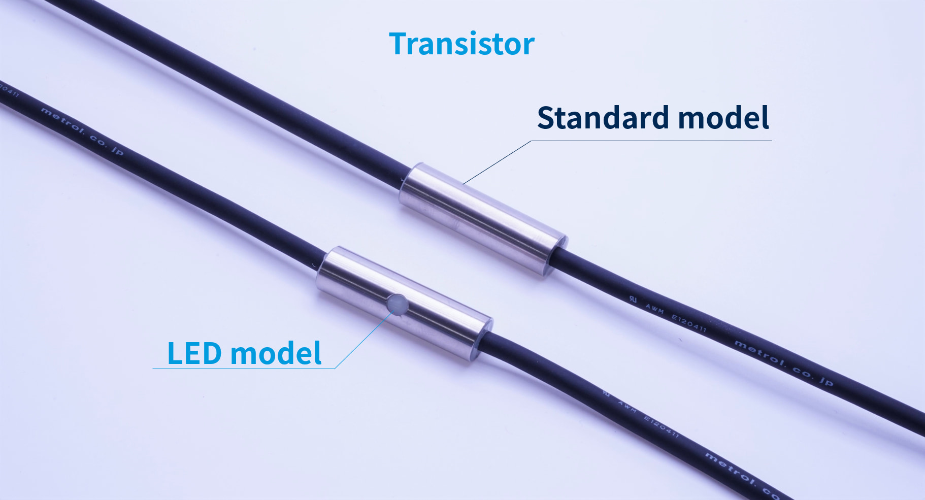
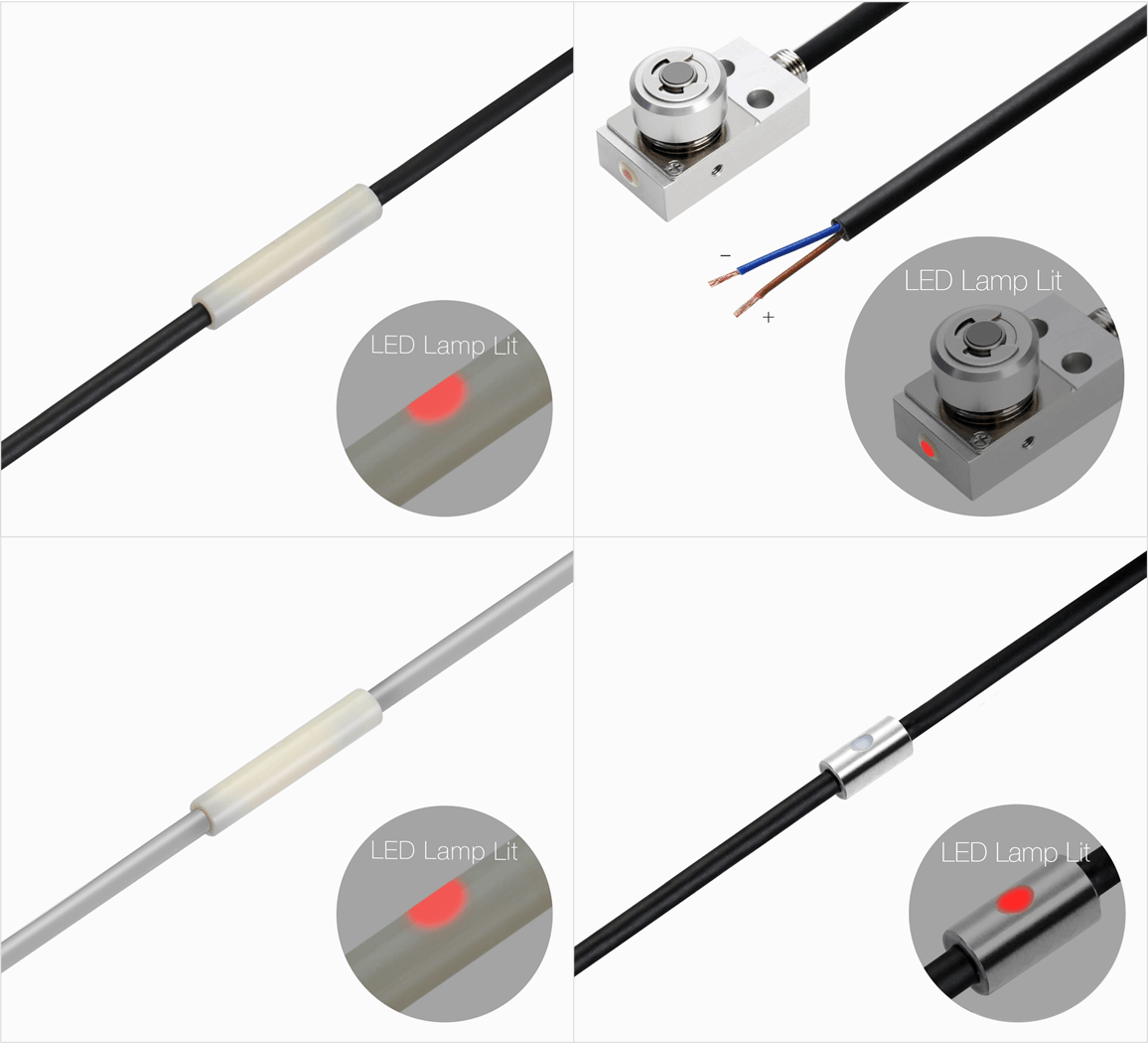
LED
The LEDs for checking sensor operation are turned on at the timing of the ON/OFF switch.
Normally closed: Selecting constant LED lighting for the NC type enables early detection of problems such as wire breakage.
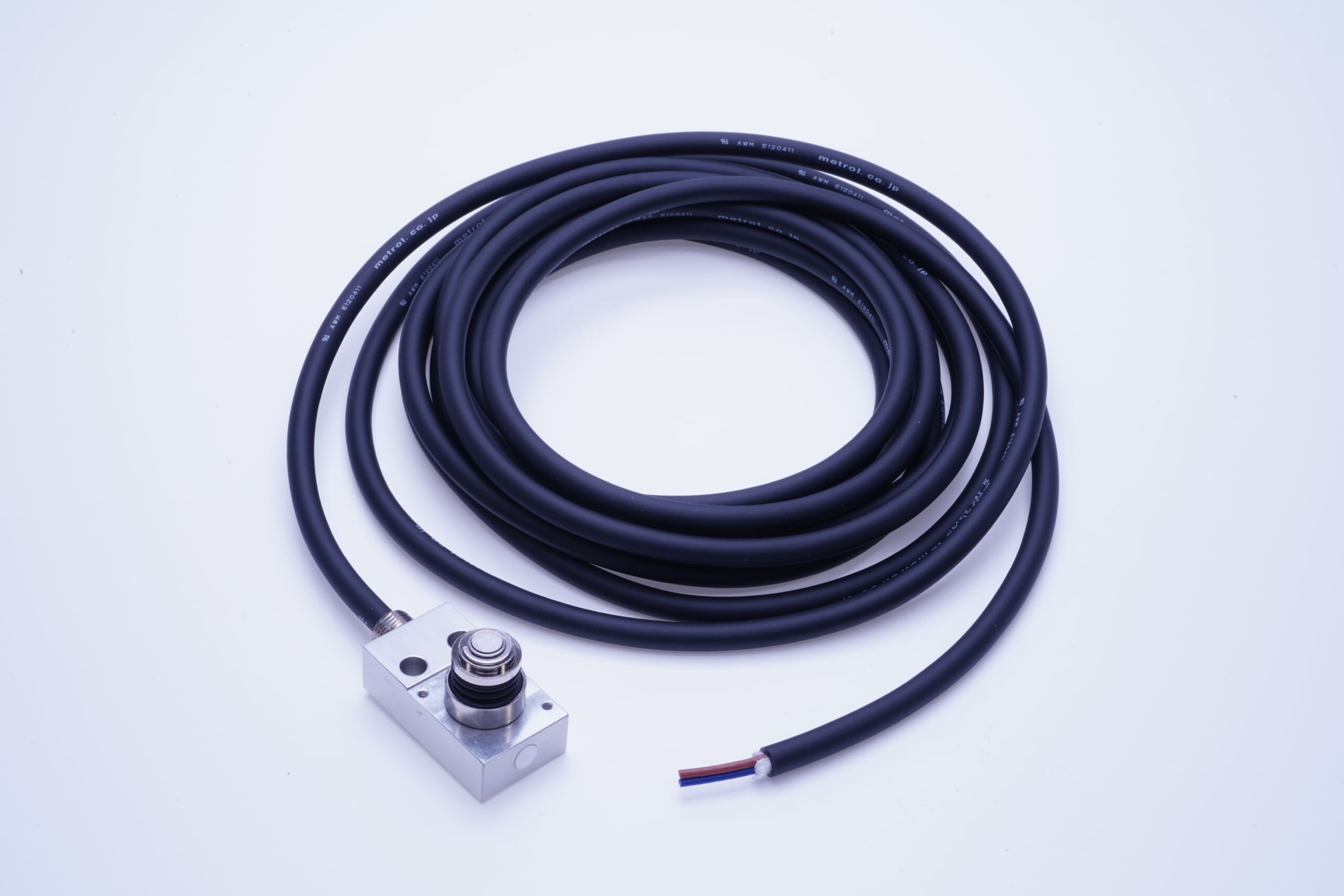
Cable protection and Cable length
The length of the cable connected to the sensor can be modified.
What are cable protection options?
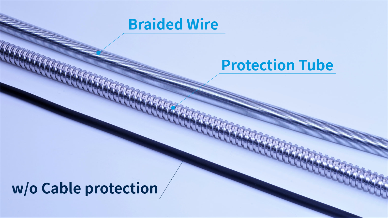
Two types of "cable protection options" are available to protect cables from wire breakage.
Prevent damages to cables caused by heavy load falling on.
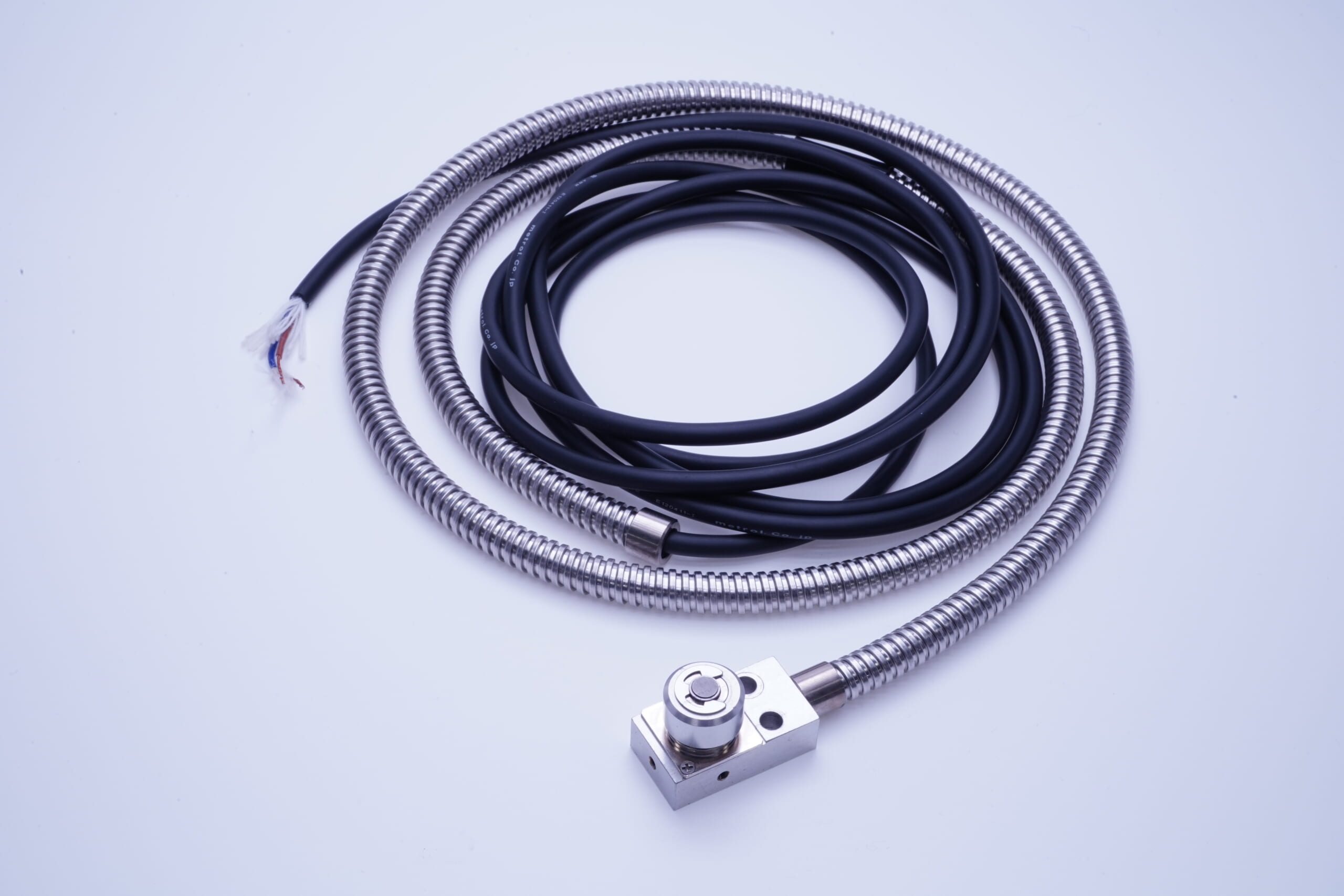
●Protection Tube
Mainly for environments subject to chips, such as inside machine tools.
Also suitable for preventing damage to cables caused by falling heavy objects. Applicable to cords of φ5 or larger.
The bending radius is as large as 25 mm due to its high sealing performance.
●Braided Wire
Braided Wire is more flexible and bendable than Protection tube (bending radius 7mm).
However, Braided Wire has a wider gap than the protection tube, which may allow small chips to enter.
*Both Protection Tube and Braided Wire do NOT have water-resistant feature.
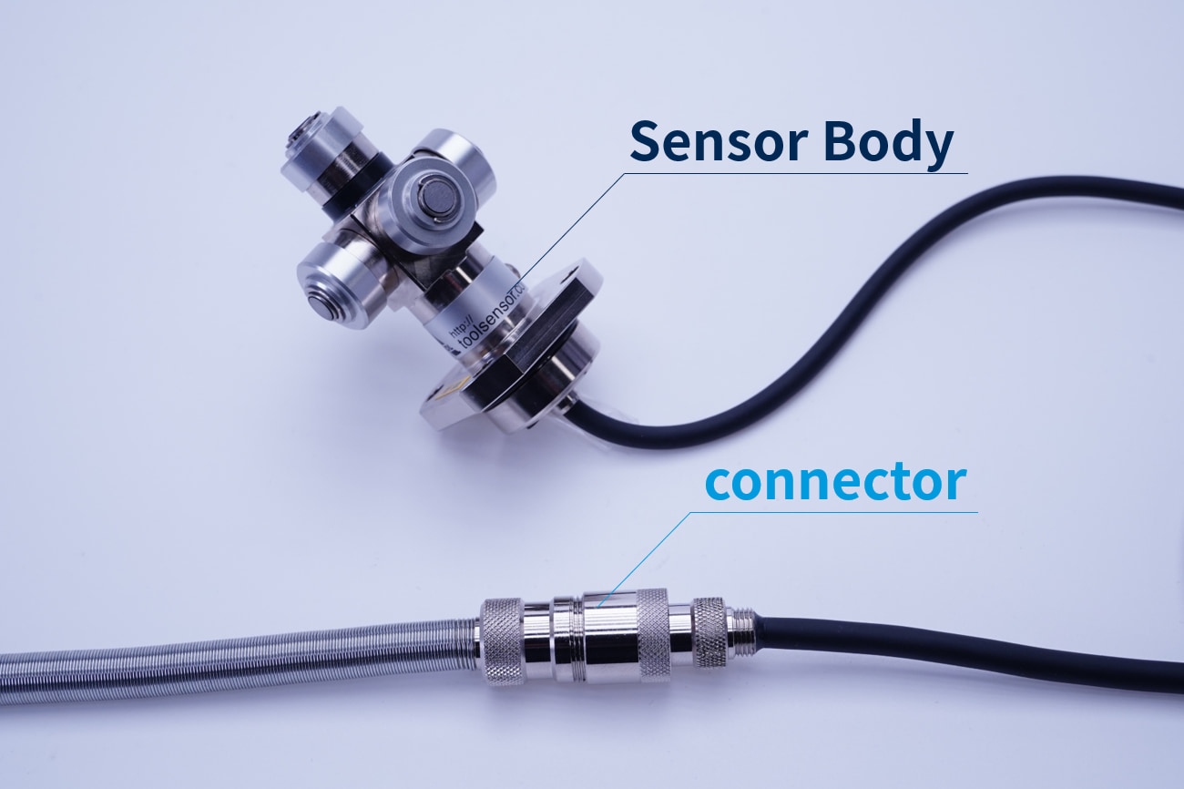
Cable connector
You may change from a normal cable to a “cable with relay connector”.
If cables are wired inside the equipment, replacement labor is required in the event of disconnection or sensor damage. By using a sensor with a connector, the sensor can be replaced without worrying about complicated wiring.
Connector positions can be specified, and cable protection options can be used in combination.
*Some products are not compatible with connectors. For details, please refer to our catalog or ask our staff.
Two types of connector options
- Relay connector
- Direct-out connector
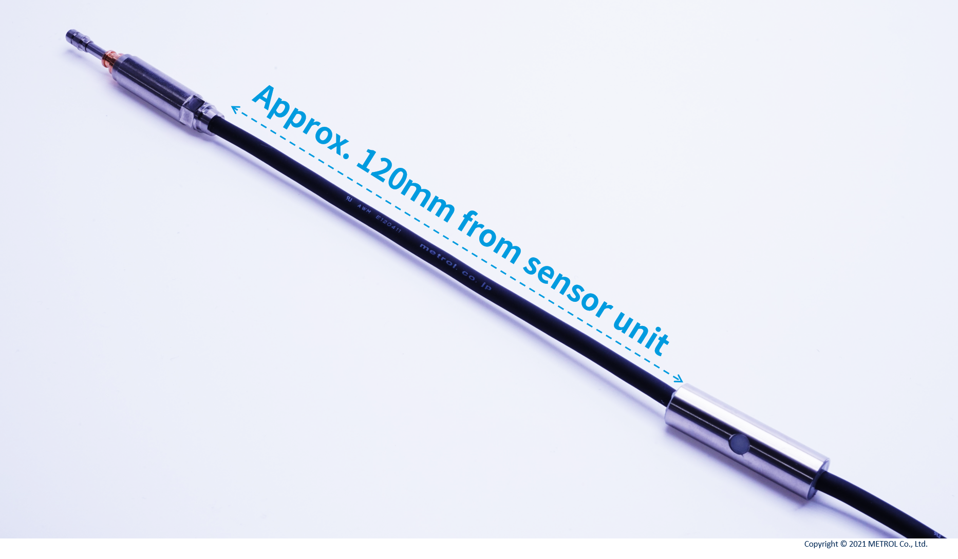
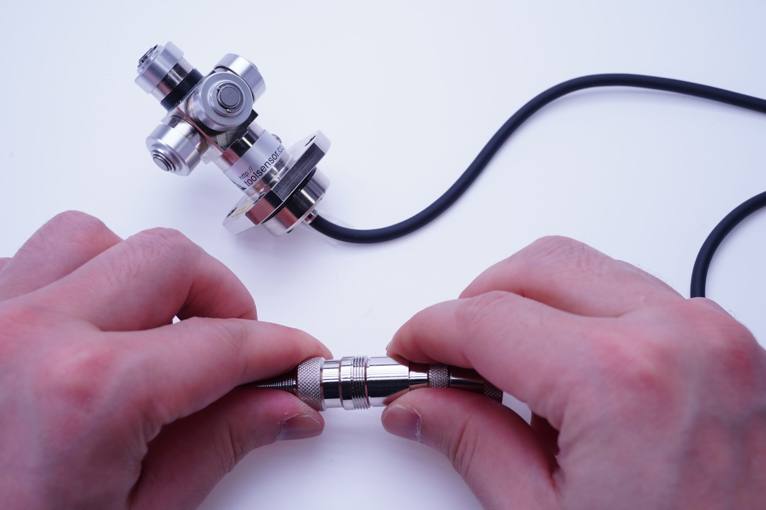
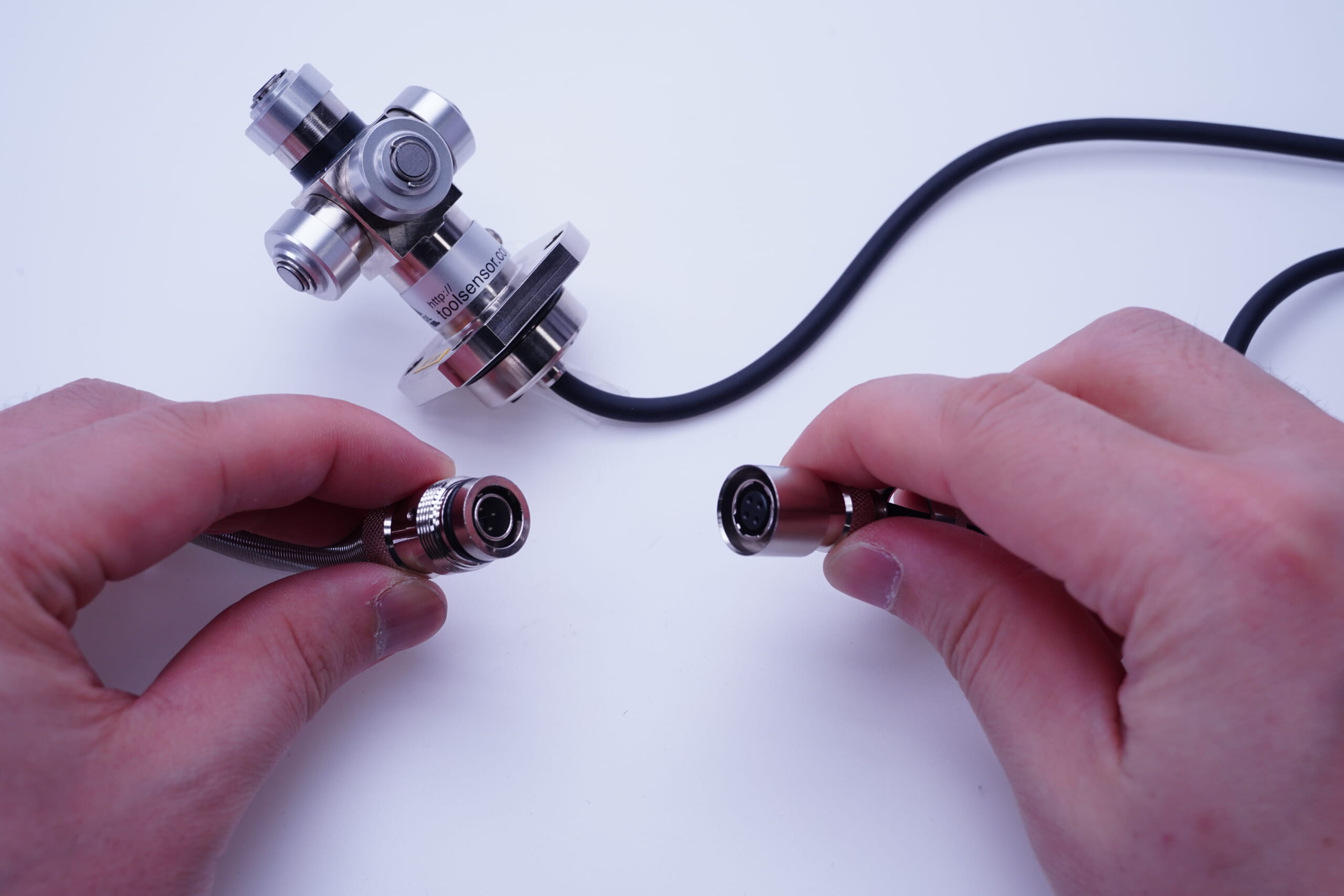
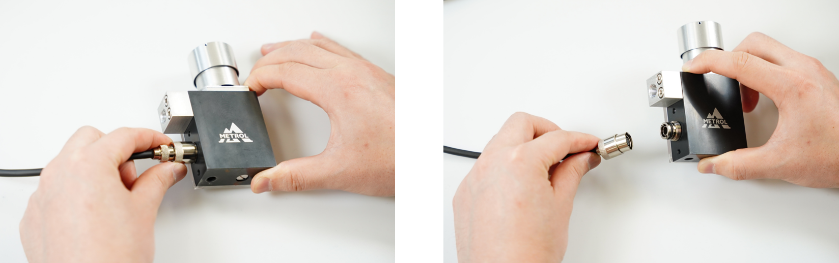
●Relay connector
A relay connector is attached in the middle of the sensor cable.
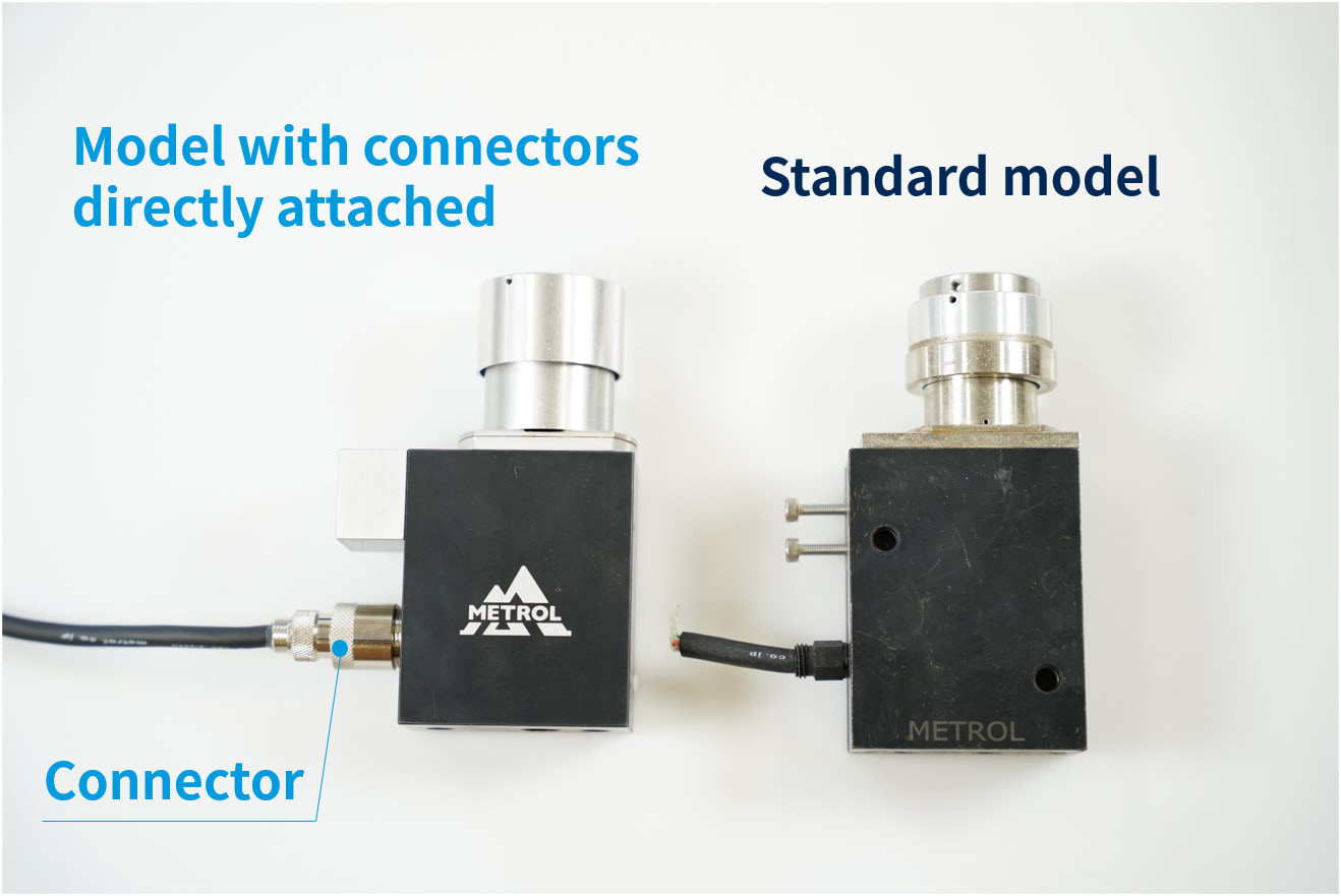
●Direct-out connector
Direct-our connector is attached directly from a sensor unit.
9) Cable Direction
Depending on the sensor mounting location, the cable direction can be changed from the standard straight direction to a right-angle direction.
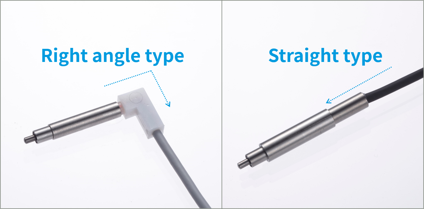
If the cable is strongly twisted, it is likely to disconnect.
we recommends to change the cable from standard straight direction to a right-angle direction depending on sensor mounting location.