What Is a Coordinate Measuring Machine (CMM)? Types and Measurement Principles
A coordinate measuring machine (CMM) is an essential device for measuring part dimensions and geometry with high accuracy in manufacturing environments.
This article explains everything from the basic structure to practical know-how in an easy-to-understand way.
Table of Contents
What Is a CMM?
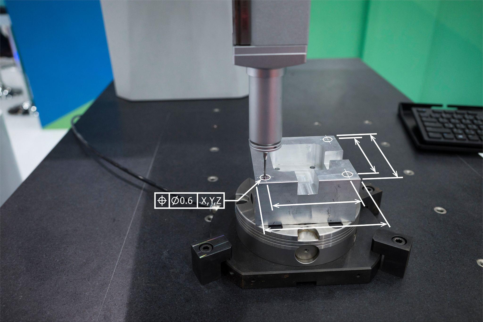
A coordinate measuring machine (CMM: Coordinate Measuring Machine) is a metrology device used to measure the geometric features of an object in three-dimensional space with high accuracy.
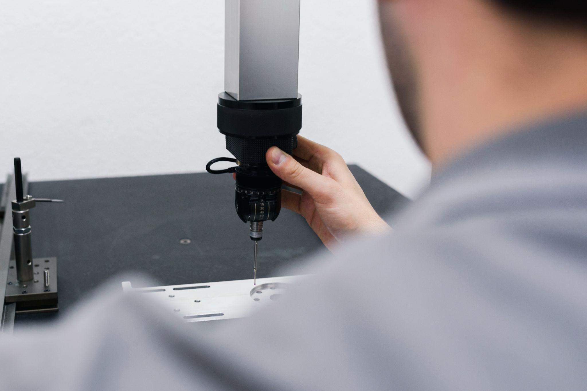
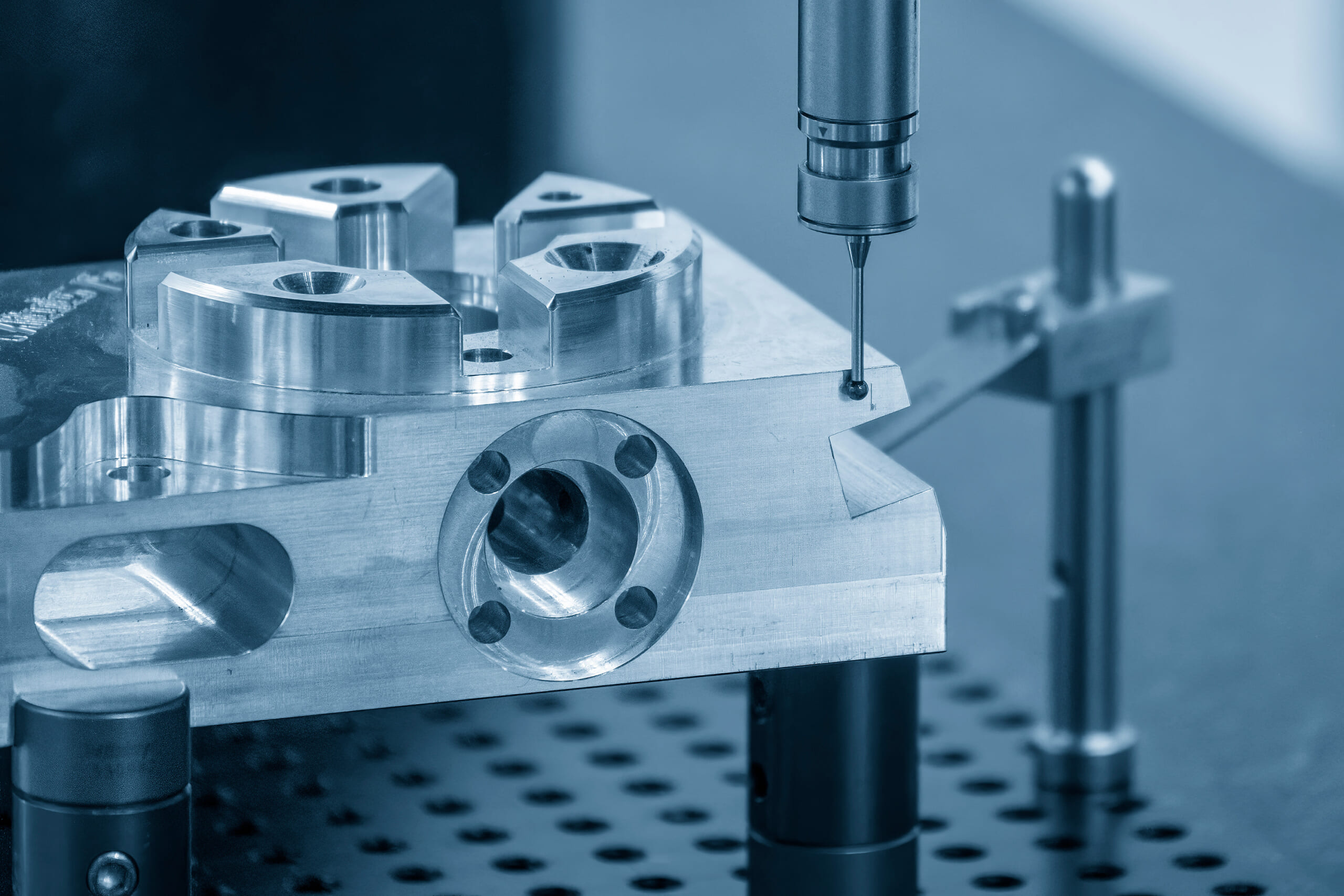
In a typical CMM, a probe detects points on the surface of the workpiece (object being measured), and the position coordinates of those points are acquired in an XYZ Cartesian coordinate system.
By measuring many points to obtain “point cloud data,” you can evaluate whether a part’s geometry, dimensions, and tolerances match the design.
CMM Types and Structures
CMMs come in several structural types, selected according to the size of the workpiece and the required accuracy. Major structural classifications include the following.
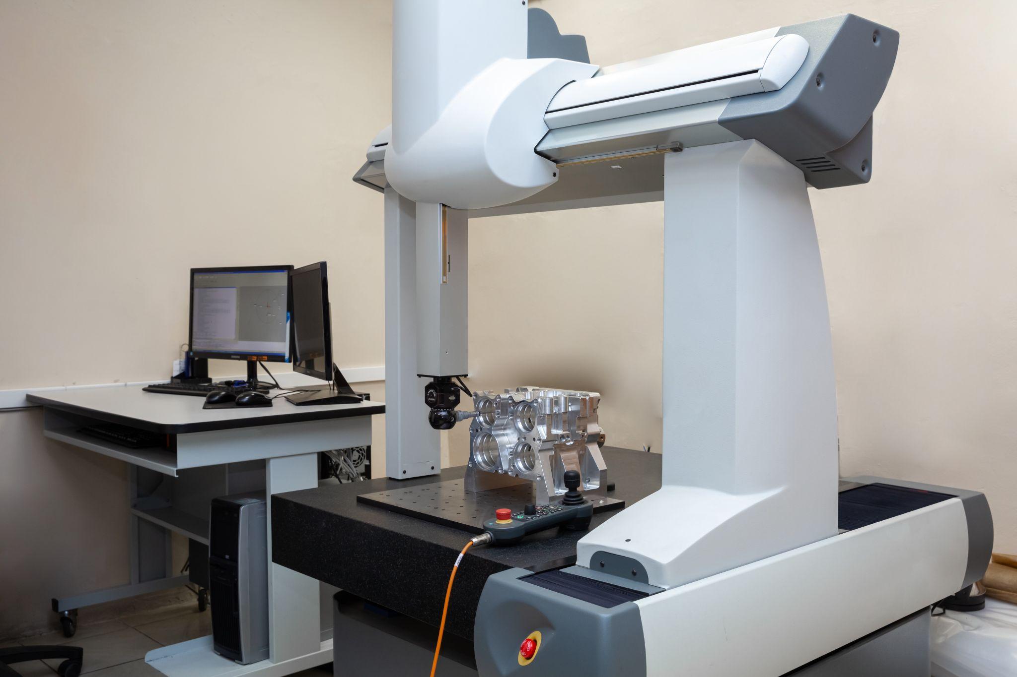
Bridge Type
This is the most common type, featuring a portal-like frame structure.
A bridge-like beam spans two uprights, and a Z-axis column carrying the probe moves up and down along the beam. In the X and Y directions, one axis typically moves the table (surface plate) while the other moves the bridge.
Because it is relatively inexpensive to manufacture and can be introduced at a reasonable cost, it is widely used and can achieve high measurement accuracy on the order of micrometers.
Cantilever Type
This CMM uses a cantilever structure in which the arm is supported only at one end.
With a column on only one side, the arm extends in the X-axis direction in a cantilevered state. Structurally, the open sides allow easy loading and unloading of the workpiece, and measurement access from three sides is a key feature.
It is especially convenient for manual operation and is useful in workplaces where handling and operability are priorities.
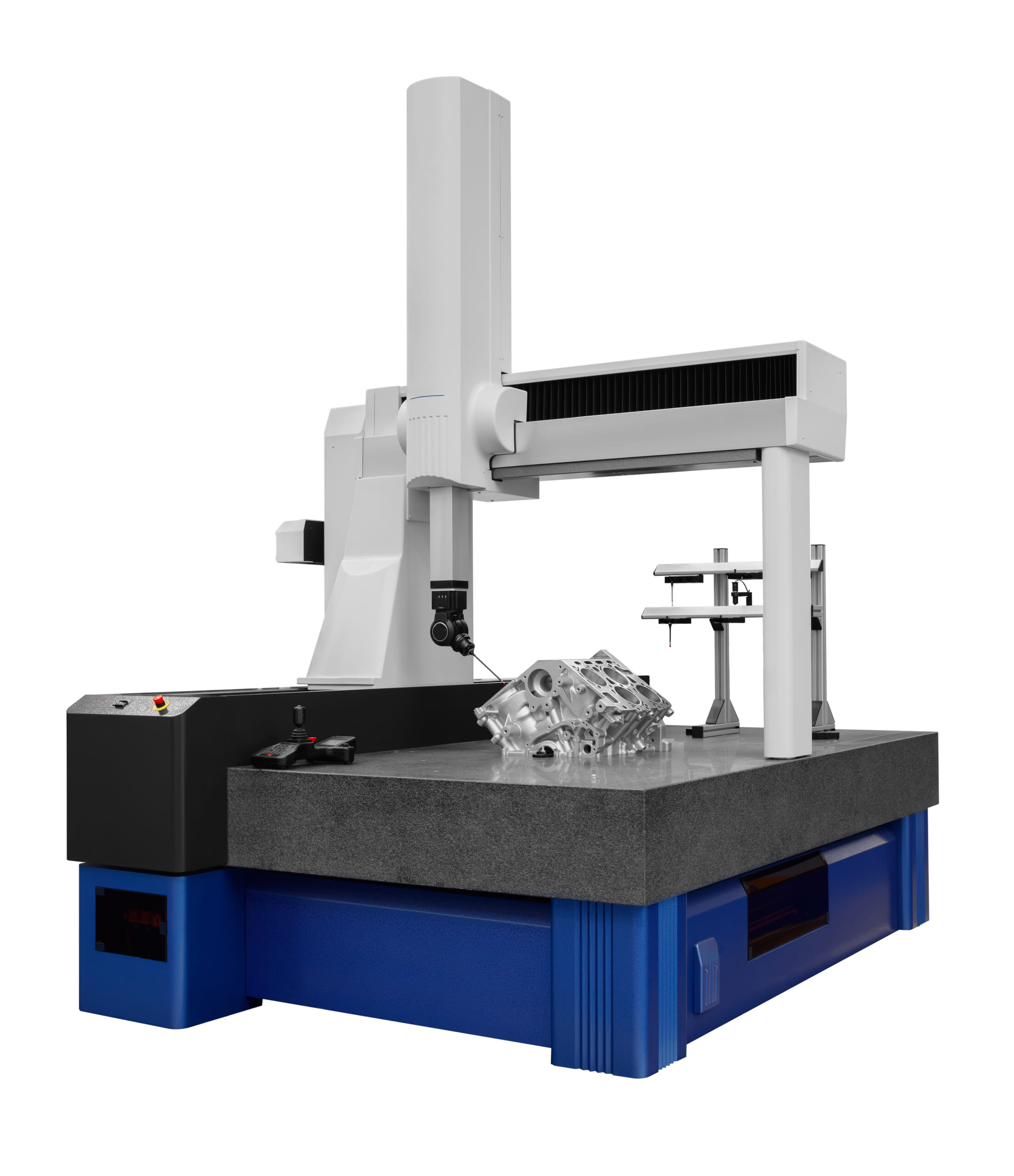
Gantry Type
This CMM has a portal frame structure similar to an enlarged bridge type, with the entire machine installed on the floor.
Designed for large and heavy workpieces, it allows even heavy parts to be placed directly on the floor-mounted surface plate using a crane or similar equipment.
By maintaining high rigidity of the bridge structure, it can sustain accuracy comparable to bridge types and is often used to inspect large parts such as aircraft components and automotive engine blocks.
Horizontal Arm Type
This CMM features a horizontally extending arm and is suitable for inspecting large structures such as automobile bodies.
Typically, a horizontal arm is attached to a vertical column and accesses the workpiece from one side (often cantilevered). Although its measurement accuracy tends to be lower than the types above, the long reach of the arm enables measurement of large parts such as automobiles, ships, and rail vehicles.
Automated workpiece centering and positioning
- Touch probe -
A contact/touch sensor for on-machine measurement that improves the efficiency of setup work
Click here ›Measurement Principles (Contact and Non-Contact)
CMMs generally use either contact or non-contact measurement principles.
Contact Measurement
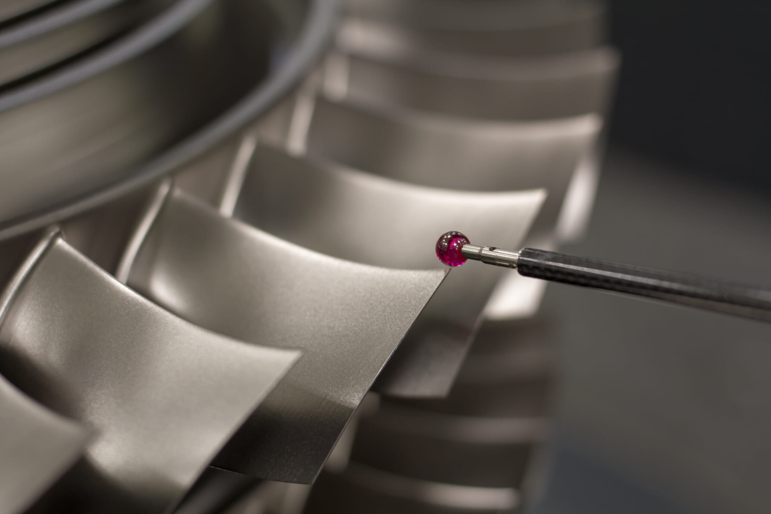
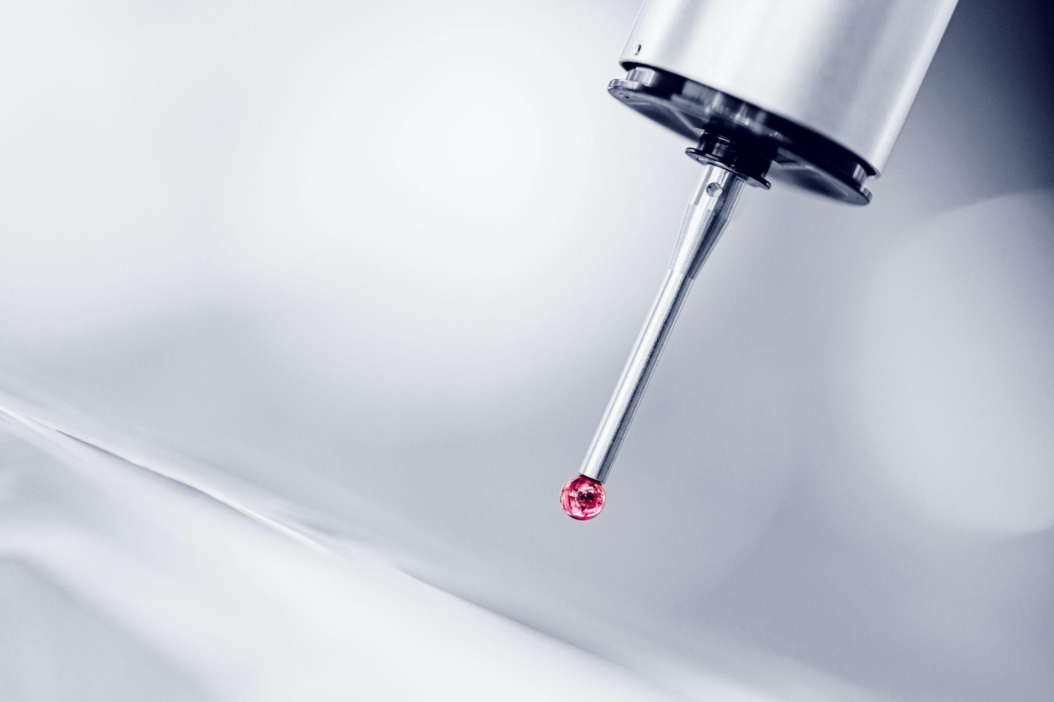
This method obtains point coordinates by directly contacting the workpiece surface with a probe (a stylus with a ruby ball or similar tip).
The most typical approach is the touch-trigger method, in which the sensor responds the moment the probe tip touches the object being measured and records the position coordinates.
Because contact measurement physically touches the surface, it can deliver high accuracy; however, repeatedly touching the same area can risk leaving tiny scratches. To address this, measures such as reducing contact force and optimizing measurement paths are applied as needed.
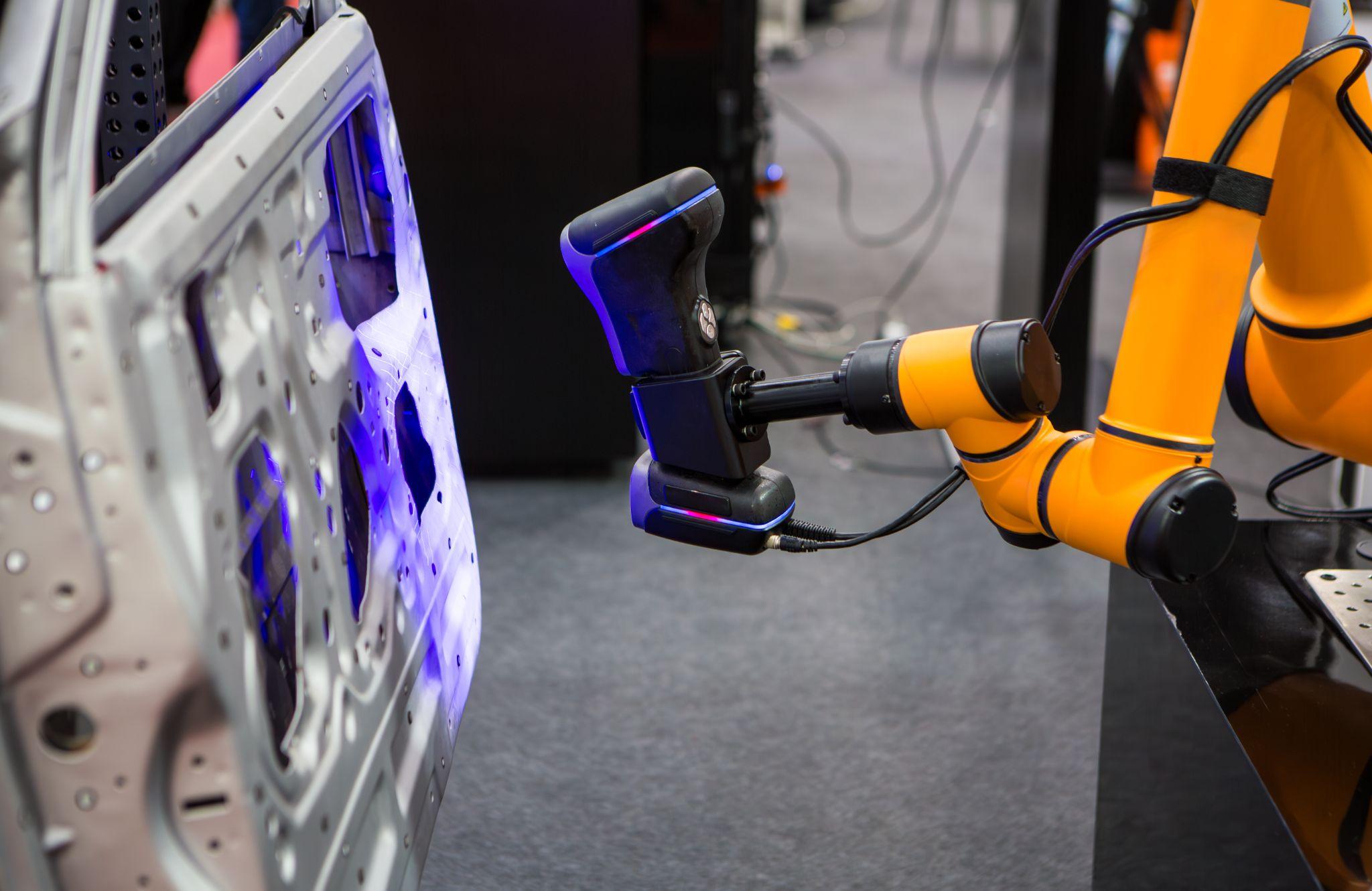
Non-Contact Measurement
This method measures dimensions without touching the object.
Common approaches use laser light, white light, or camera images; instead of physical contact, optical methods capture distance and shape.
Examples include measuring distance to the target with a laser range finder or detecting edge positions with a CCD camera.
The biggest advantage of non-contact measurement is that it does not damage the workpiece, making it suitable for soft materials, miniature parts, or extremely fine finished surfaces.
Why High-Accuracy Probes Matter
Even if the CMM itself is highly accurate, high-precision 3D measurement is not possible if the probe that directly touches the workpiece has low accuracy.
For this reason, probes are expected to provide the following performance.
Easy Handling
Because probes are basically consumables, being “easy to replace” when wear or deterioration occurs over long-term use is an important factor.
If replacement takes significant time or requires calling a service engineer, maintenance costs rise accordingly - and you may end up not replacing the probe in the name of cost reduction, which can prevent you from maintaining high accuracy.
Ease of replacement when wear or degradation occurs is a key element for reducing operator burden and maintaining accuracy.
Resistant to External Noise and Able to Reliably Transfer Measurement Data to the CMM
Even if you use a probe that is easy to work with and enables high-accuracy measurement, it is meaningless if the measurement data cannot be reliably transferred to the CMM.
Resistance to “external factors that hinder high-precision measurement,” such as machine vibration, dust, airflow caused by temperature differences, and noise from electronic equipment, is essential.
To minimize measurement errors caused by external factors, the probe must be designed to reliably transmit measurement data to the CMM.
Low Load on the Workpiece
Because probe-based measurement “directly contacts the workpiece,” excessive contact load may scratch the product or even cause damage.
Because probe-based measurement “directly contacts the workpiece,” excessive contact load may scratch the product or even cause damage.
Therefore, low load on the workpiece is also an important point for accurate and safe measurement.
Automated workpiece centering and positioning
- Touch probe -
A contact/touch sensor for on-machine measurement that improves the efficiency of setup work
Click here ›Measurement Basics
There are two basic measurement approaches on a CMM: point measurement (discrete single-point measurement) and scan measurement (continuous surface measurement).
Point Measurement
This method measures only specific points using a touch-trigger probe or similar device.
For example, it may measure several points around a circumference to determine a hole center, or detect points at several locations to evaluate the flatness of a plane.
Point measurement provides a limited amount of information per run, but it is often sufficient for checking specific dimensions, positions, and tolerances, and measurement time is relatively short. With smaller data volume, analysis and management are also easier.
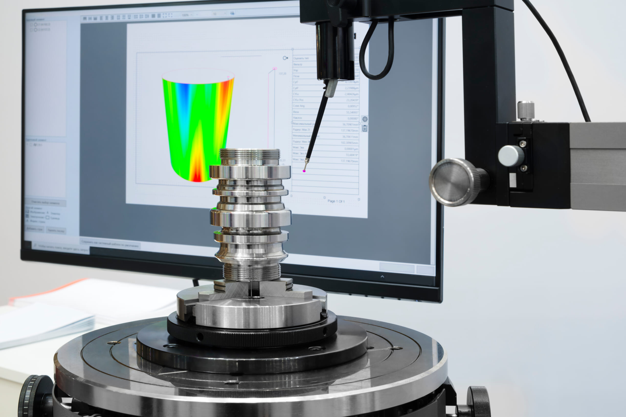
Scan Measurement
This method uses a scanning probe or non-contact sensor to continuously scan the workpiece surface and acquire a large amount of point cloud data.
It is suitable for digitizing contours such as cylinders, spherical surfaces, and freeform curved surfaces. Scan measurement can be performed with either contact or non-contact methods, and is characterized by the ability to measure the geometry of an entire surface with high accuracy in a short time.
How to Choose a Stylus for Measurement
To obtain highly accurate measurement results, selecting an appropriate stylus is essential. Continuing measurement work under conditions where accurate measurement is not possible - by hesitating to spend time or money on probe or stylus replacement - can risk losing “the accuracy of your products and your customers’ trust.”
For choosing a stylus suitable for the material being measured, refer to the points below.
Keep the Stylus as Short as Possible and Minimize Joints
Use a stylus that is as short as possible and ideally has no joints.
Styluses are made from rigid materials such as carbide, steel, ceramic, or carbon fiber; however, long styluses or those connected with extensions are more prone to errors caused by deflection, bending, or deformation.
To minimize geometry-related errors, it is recommended to keep the stylus as short as possible and use it with as few connections as you can.
Use the Largest Possible Stylus Ball
Probe measurement is performed by “bringing the stylus ball at the tip into contact with the workpiece,” and you should choose a stylus ball larger than the shaft. This reduces measurement errors caused when the shaft interferes with the workpiece before the ball does.
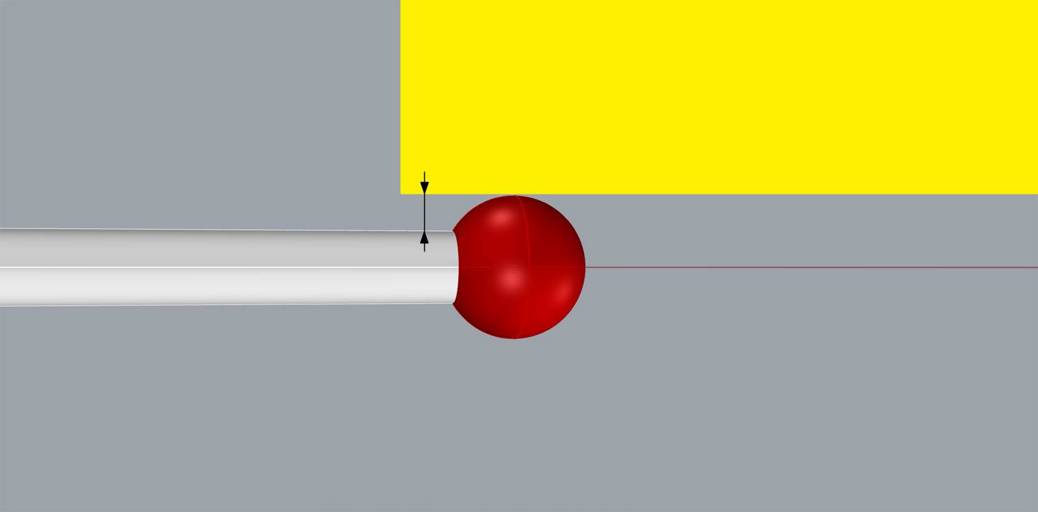
When the ball is larger than the shaft, the gap between the workpiece and the shaft becomes larger as shown in the figure, making accurate measurement easier - so use the largest possible stylus ball.
Choose the Stylus Ball Material to Match the Workpiece Material
In many workplaces, probes commonly use a red ruby stylus ball.
Ruby balls have a smooth surface, high compressive strength during contact, and strong resistance to mechanical corrosion, so they are used for measuring a wide range of materials. However, if you want to minimize wear during scanning measurement, consider selecting the following materials as well.
- Silicon Nitride
Silicon nitride is an extremely hard ceramic material, with a Vickers hardness of 1300-1600 and a Mohs hardness of 8.3-9, second only to diamond.
It has properties similar to ruby, but it does not cause “adhesive wear that can occur when measuring aluminum products” as ruby can, making it suitable for measurements focused specifically on aluminum products.
- Zirconia
Zirconia has hardness and wear resistance close to ruby, with a Vickers hardness of 1200–1600 and a Mohs hardness of 8–8.5, and is ideal for scanning products such as cast iron.
Automates originating of cutting tools
- Tool Setter -
Tool length and chips are monitored to prevent machining defects due to wear and thermal displacement
Click here ›What Are Metrol’s High-Precision Positioning Sensors?
Coordinate measuring machines (CMMs) are widely used as high-precision metrology systems that support quality control in manufacturing.
At the same time, further automation and labor reduction on production lines require accurate and efficient positioning between machines and precise workpiece setup.
That is why the latest positioning sensors offered by Metrol are drawing attention.
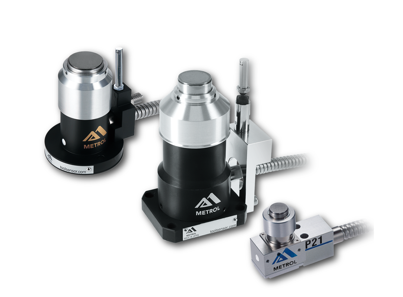
High-Precision Positioning Touch Switches
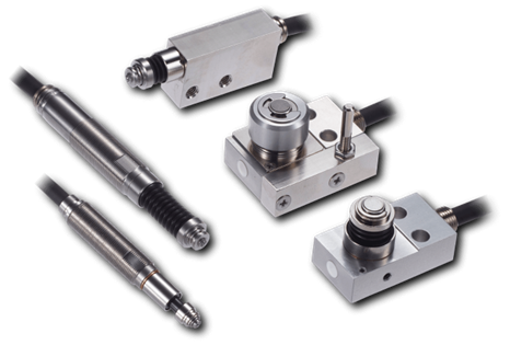
These are contact-type high-precision switches used for positioning and workpiece presence detection in machine tools, robots, and jigs. They achieve an extremely high repeatability of up to 0.5 µm and feature IP67-rated waterproof and dustproof protection, ensuring stable operation even in harsh environments. With more than 200 standard models available, they offer a wide range of variations, including designs for confined spaces, high-temperature environments, vacuum applications, and low contact force requirements.
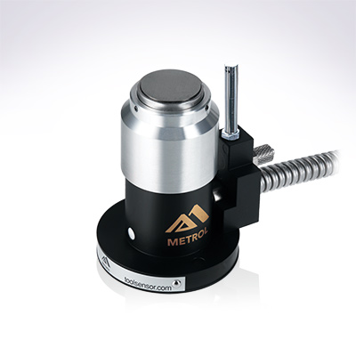
Tool Setter (Tool Length Measurement Sensor)
This is a contact-type sensor installed on CNC machine tools and industrial robots for tool length measurement, reference position setting, and tool breakage detection. By automatically measuring and compensating for tool length, wear, and thermal displacement inside the machine, it helps prevent machining defects and significantly reduces setup time. It is one of Metrol’s best-selling products, with a proven track record of more than 500,000 units shipped in 74 countries worldwide.
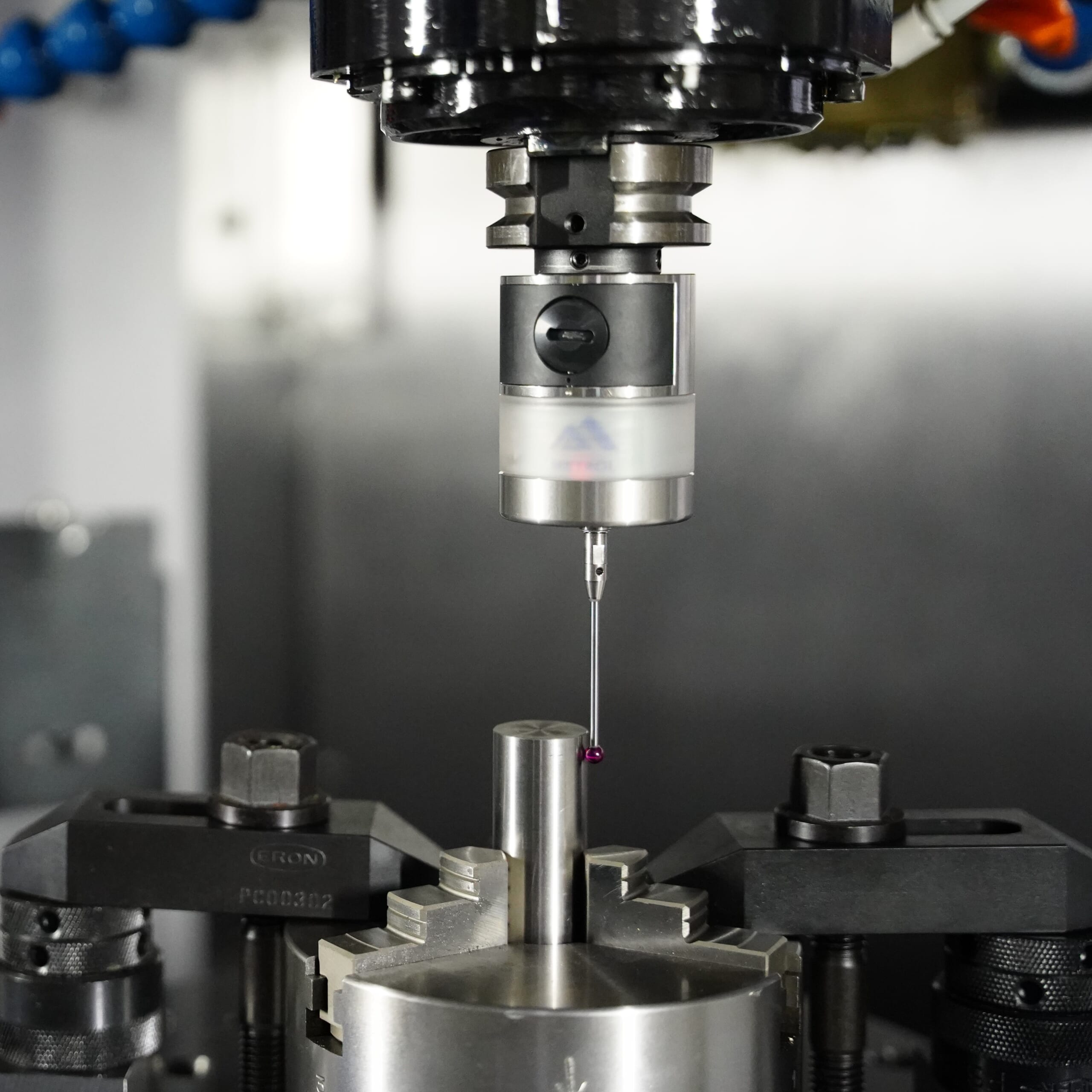
Touch Probe (On-Machine Measurement Probe)
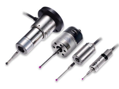
This is a contact-type probe for in-machine measurement, installed on machine tools and robots to automatically perform workpiece positioning (centering) before machining and dimensional measurement after machining. With a repeatability of 1 µm, it automates workpiece referencing and dimensional inspection, replacing skilled manual operations to reduce setup time and help prevent machining defects. Both wired and wireless models are available, meeting retrofit needs for 5-axis machining centers and robotic applications.
Air Gap Sensor (Pneumatic Sensor)
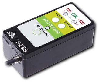
This is a non-contact sensor that uses air pressure to detect workpiece seating conditions with micron-level accuracy. It can detect gaps (“lift”) of less than 10 µm—previously difficult to measure—with a repeatability of ±0.5 µm, helping prevent machining defects and equipment downtime caused by insufficient contact between the workpiece and fixture. The sensor is used in applications such as semiconductor manufacturing processes, precision part clamping operations, and grinding wheel positioning on grinding machines, and it is a smart sensor that also supports the international standard IO-Link communication.