Automation of NC Grinding Machines [Introduction]
NC Grinding Machine manufacturers and users experience the following challenges daily.
- Manually applying the grinding wheel to the workpiece, and watching for sparks / listening for sounds to confirm the machining start position can be time consuming.
- Veteran and new employees cannot standardize the quality variance for the grinding wheel application process.
- AE sensors are used, but accuracy is unstable.
In machine tools, NC grinding machines demand high-precision machining to determine the dimensions of the workpiece.
Therefore, even when NC is utilized, automation comes with a high degree of difficulty, and many users are faced with the challenge of manpower shortages at their sites.
This article provides an in-depth look at METROL's industry-first efforts to fully automate NC grinding machines using Air Gap Sensors.
What you will learn from this article
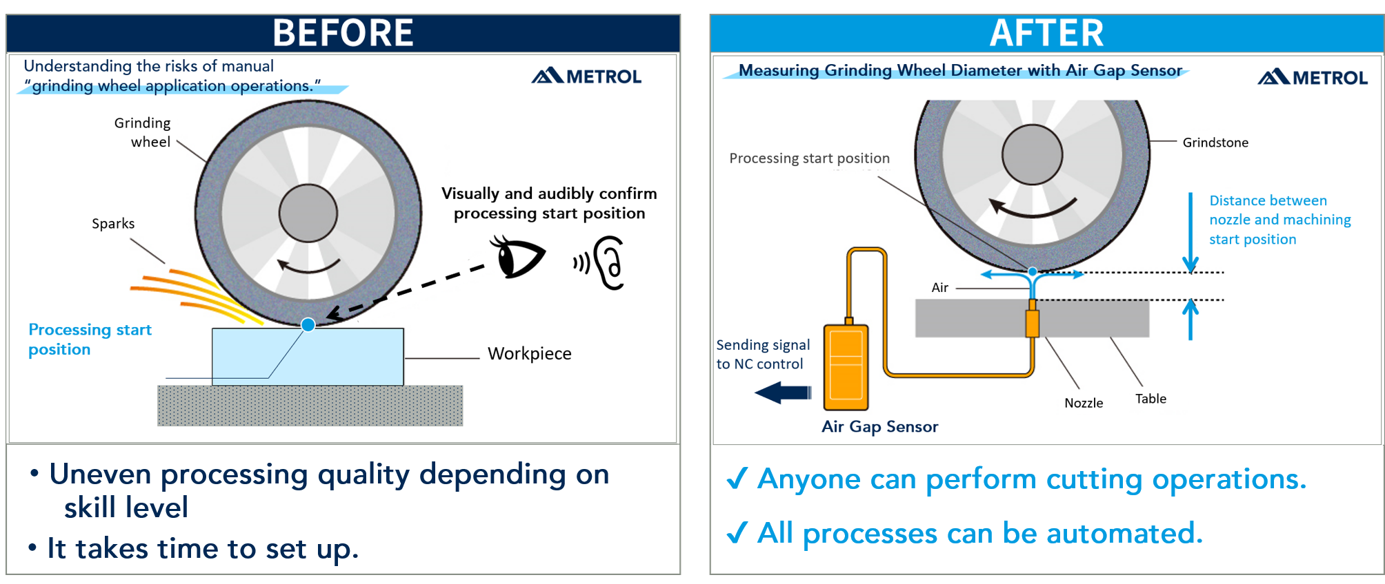
- Understanding the risks of manual “grinding wheel application.”
- Understanding how to use Air Gap Sensors to automate NC grinding machines.
- Understanding how to automate the “grinding wheel application process” using Air Gap Sensors.
- Understanding NC grinder machine automation case studies
Table of Contents
[Issue] What is the “grinding wheel application process” for an NC grinding machine?
Normally, the following two setup operations are essential when machining a workpiece on an NC grinding machine.
- Indexing the start position for grinding wheel machining
- Workpiece start position
In general, the process of determining the start position for grinding wheel machining (i.e., the diameter of the grinding wheel) is called the “grinding wheel application process.”
This “grinding wheel application process” is a difficult and challenging task.
Implementing the “Grinding wheel application procedure”
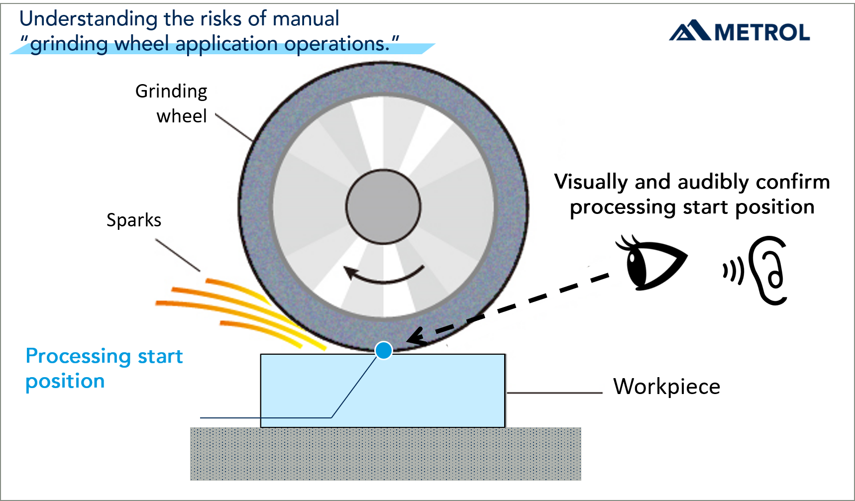
The general practice is to first manually bring the rotating grinding wheel slowly to the workpiece surface, and bring it into contact.
The “machining start position” can be determined by the sparks and sounds produced when the grinding wheel contacts the workpiece.
As the machining point of the grinding wheel is displaced by thermal displacement and wear of the grinding wheel, it is necessary to correct the start position of machining while periodically performing “grinding wheel application” operations.
Tip: Can the “grinding wheel application procedure” be performed anywhere?
When we interviewed NC grinding machine users at the Mechatronics Technology 2021 exhibition, we found that 24 of the 30 companies were performing the “grinding wheel application procedure” and the remaining 6 were using AE sensors.
Some companies use a pen to mark the workpiece, then grind off and zero in on the position where the marker disappears.
Next, we will explain the risks associated with this “grinding wheel application procedure.”
What are the risks in the “grinding wheel application procedure” for an NC grinding machine?
The “grinding wheel application procedure” described in the previous section has the following issues and risks.
- Manual labor is required for each application, and full automation is not possible.
- Machining accuracy and man-hours are not consistent between new and experienced workers.
- Direct contact of the grinding wheel with the workpiece causes them to become damaged immediately after dressing.
- The risk of the grinding wheel hitting the workpiece causing an accident.
These issues of human error and skill acquisition are difficult to solve overnight.
In order to build a sustainable and safe production system, solutions are needed through standardization and automation of skills.
What is automation of the “grinding wheel application procedure” for an NC grinding machine?
At METROL, we have long studied the automation of the “grinding wheel application procedure,” which has been a manual job, achieving this with our Air Gap Sensor-based method.
What is the “Air Gap Sensor?” The measurement principle of the sensor explained.
What is the “Air Gap Sensor” that automates NC grinding machines?
Put simply, the Air Gap Sensor is “a high-precision positioning sensor that uses air (air nozzles) to detect the distance to an object as Valid/Invalid.”
A “distance threshold” that serves as a Valid/Invalid criterion is registered to the sensor in advance, and the sensor accurately determines whether the distance between the object and the air nozzle is closer or farther than the threshold value.
[Explanation] Air Gap Sensor use case study
The use of the Air Gap Sensor is explained by “checking whether a workpiece is present or not” as an example.
Example: Procedure when sensor threshold = 10 μm set.
- Step 1: Register “10μm distance threshold” to the sensor in advance.
- Step 2: Move the workpiece close to the nozzle to detect its presence or absence (see Figure 2).
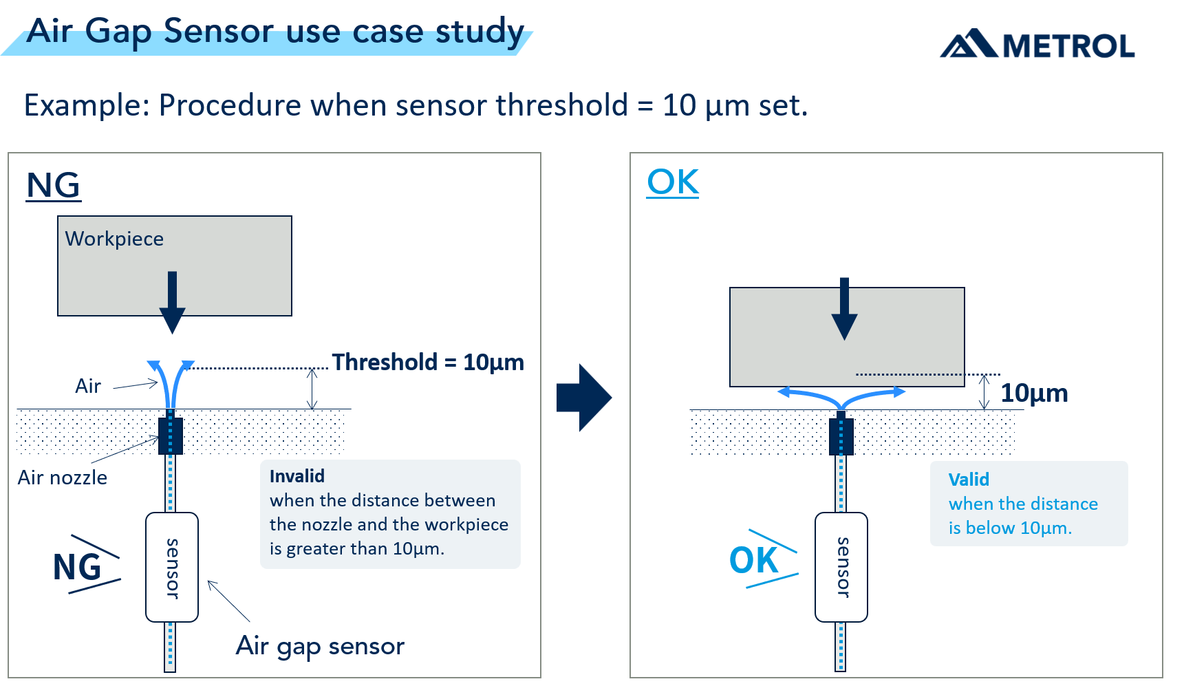
When the distance between the workpiece and the nozzle is greater than the threshold value (=10µm) → Invalid signal output. [Left Fig. ]
Approaches until the distance between the workpiece and nozzle is 10 μm or less → Switches to the Valid signal. [Right Fig.]
Tip: How can distance be detected by air? What is the principle the sensor uses for detection?
The sensor detects changes in flow rate and back pressure in air supplied from the air nozzle to determine the Valid/Invalid judgment.
When the workpiece approaches the nozzle, the nozzle (hole) is blocked and the air supply restricted. As a result, the pressure in the sensor changes. The distance to an object is detected using minute changes in back pressure.
Explanation of automation of NC grinding machines using sensors
The following illustration and photos show how to automate the grinding wheel application procedure using an Air Gap Sensor. The detection target in NC grinding machines is not the workpiece but “the start position of the rotary grinding wheel.”
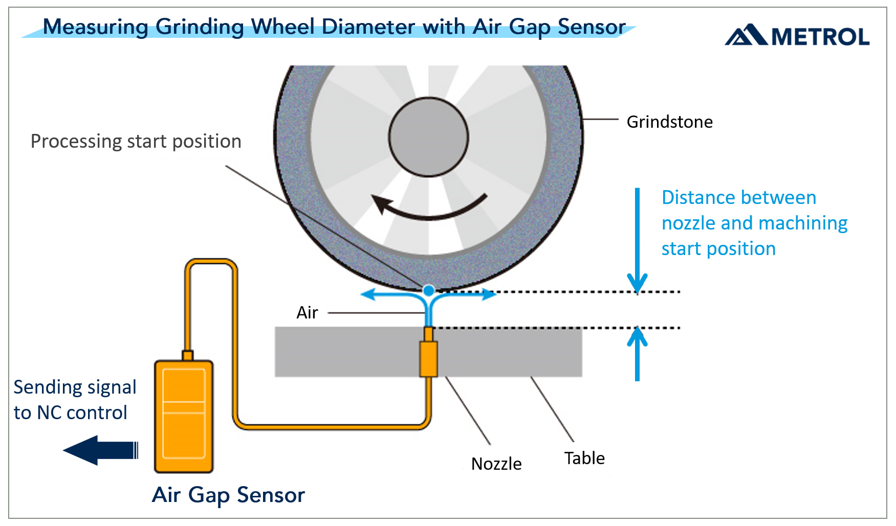
[Illustration] Procedure for detecting the machining start position using an Air Gap Sensor.
- Installing air nozzles on NC grinding machines.
- Grinding wheel in rotation approaches air nozzle.
- Position at which sensor signal switches → Machining start position (see Fig. 3)
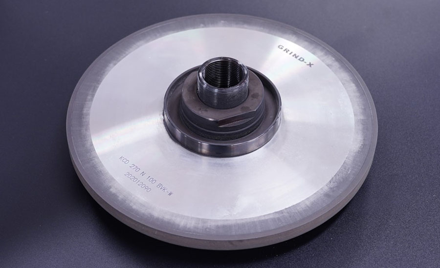
[Photo Description] Procedure for detecting the machining start position using Air Gap Sensors.
The actual air nozzle and grinding wheel are shown in enlarged photographs to illustrate the detection procedure.
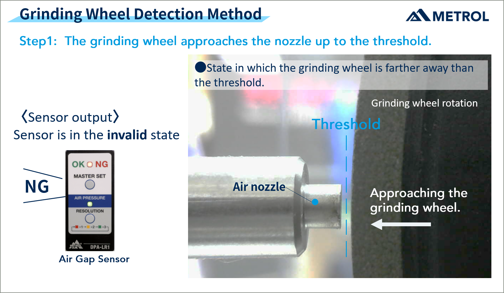
Procedure 1: Grinding wheel in rotation approaches air nozzle.
The distance between the nozzle and the grinding wheel is greater than the threshold value, and the sensor is in the Invalid signal state. (Refer to Fig. 4)
The grinding wheel moves closer to the nozzle until it reaches the threshold position where the signal switches to Valid.
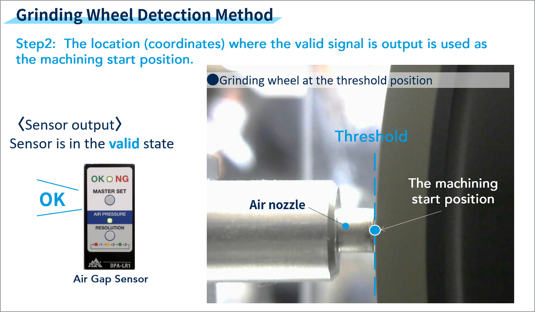
Step 2: Position at which signal switches is the machining start position.
When the distance between the grinding wheel and nozzle reaches the threshold, the sensor switches to the valid signal.
By reading the coordinates at which the sensor switches to the valid signal, the “grinding wheel machining start position” can be determined.
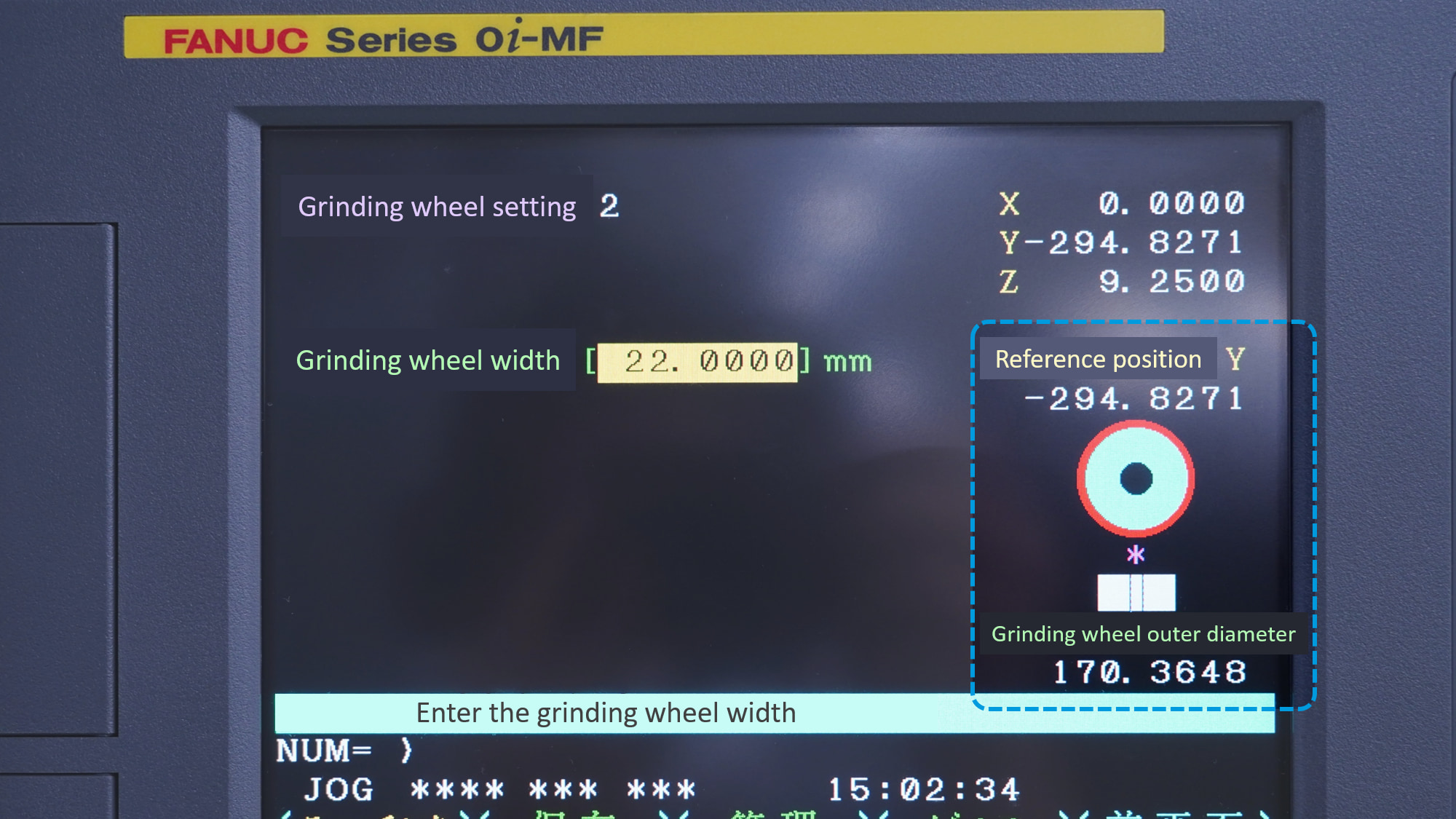
Step 3: Calculates the grinding wheel diameter by arithmetic operation.
The outer diameter of the grinding wheel can be calculated from the coordinates of the reference position of the wheel when the sensor signal is output.
[Summary] Automation of grinding wheel application procedure.
As described above, through steps 1 through 3, the “grinding wheel application procedure” that was previously performed manually is now fully automated.
*It is also necessary to detect “workpiece height” with a Touch Probe or similar device.
[Video Commentary] NC grinding machine automation
The measurement procedure for grinding wheels described in the previous chapter is introduced in the video which shows the actual NC grinding machine in action.
[Use Example] NC grinder machine automation case study
The “automation of the rotary grinding wheel application procedure” has been adopted as an optional “non-contact sensor capable of measuring grinding wheel diameter” on the CNC grinding machines of Okamoto Machine Tool Works - a major manufacturer of grinding machines.
[FAQs] Regarding NC grinding machine automation
The following are answers to frequently asked questions about measuring the start position for of grinding wheel machining.
Can I measure while coolant is still on the grinding wheel?
Coolant must be stopped when measuring.
After the coolant is stopped, the grinding wheel should be rotated for a few seconds to remove moisture before measuring for more accurate results. Grinding wheels that contain coolant (moisture) may not be measured accurately due to expansion.
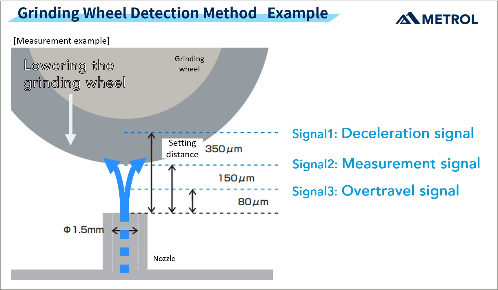
How many sensor signals can be produced?
Up to 3 signals can be registered. By setting thresholds according to the objective, highly productive control is possible.
Examples include “measurement signals” to see the position of the grinding wheel, “deceleration signals” to control the approach speed of the grinding wheel, and “overtravel signals” to prevent collisions.
Up to what grinding wheel grain size can be seen?
The finer the abrasive on a precision grinding wheel, the higher the repeatability and thus the more accurate the measurement.
Precision grinding wheels such as diamond and CBN wheels can be measured with repeatability of up to 1 μm.
Please ask our team for details.
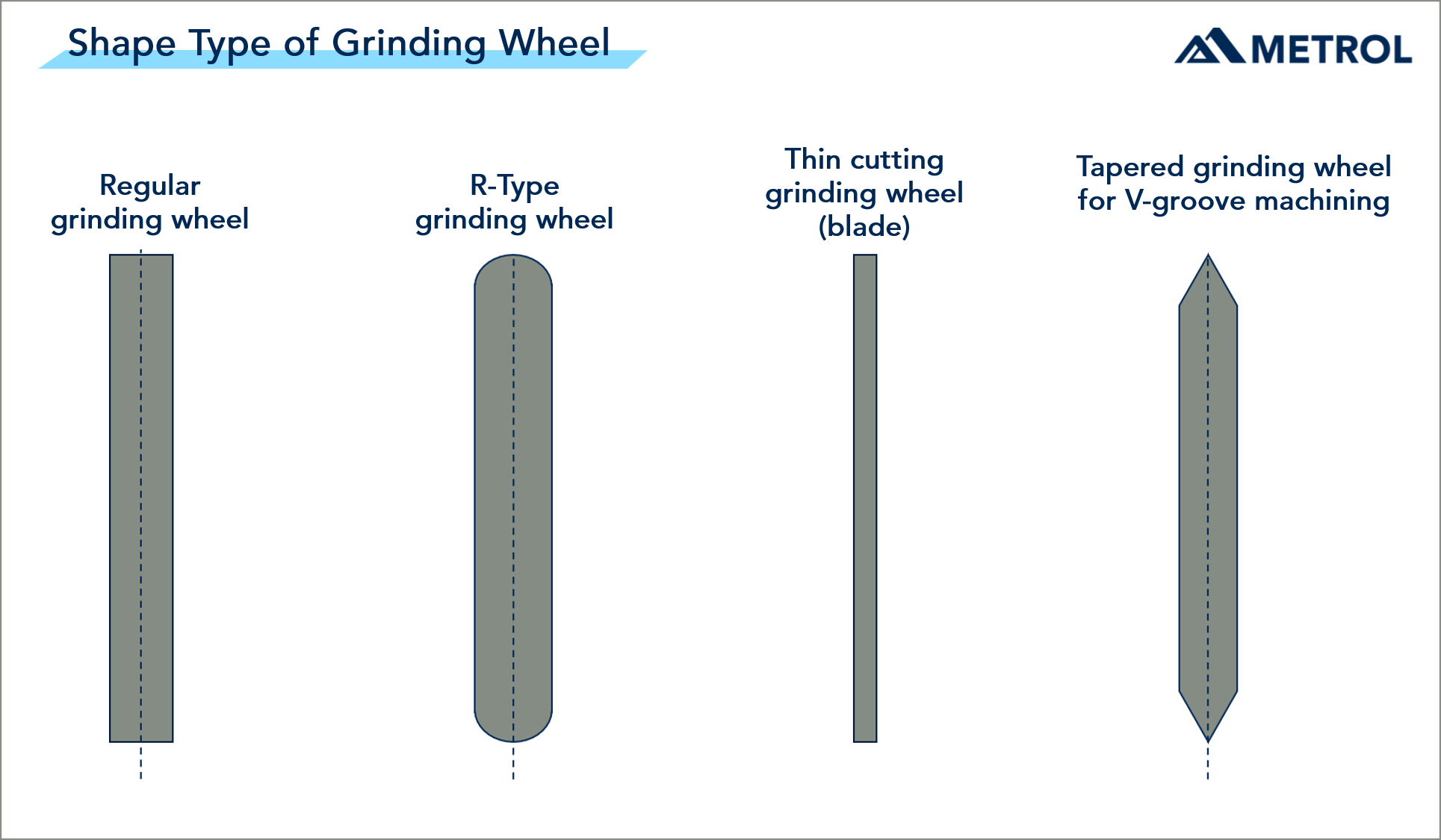
Can grinding wheels of any shape be measured?
- Regular grinding wheel
- R-Type grinding wheel
- Thin cutting grinding wheel (blade)
- Tapered grinding wheel for V-groove machining
Each grinding wheel shape requires a different detection method. Contact us for support.
At how many rpm should the grinding wheel be measured?
As a guide, it is recommend that measurements be taken at the same rpm as during processing. For specific rpm, please contact us for support.
Where is the Air Gap Sensor installed?
Since the shorter the air piping length between the air nozzle and the sensor, the better the response, it is recommended that the sensor be installed close to the air nozzle.
The Air Gap Sensor is IP67 and resilient against cutting oil, so can be installed inside the machine.
Is installation possible on a regular machine, rather than a NC grinding machine?
Installation on regular machines is not recommended as it is difficult to align the nozzle with the grinding wheel.
What’s required to introduce NC grinding machine automation?
Currently, we have a proven track record with installations on NC grinding machines manufactured by Okamoto Machine Tool Works, Ltd. Please feel free to inquire.
We welcome your inquiries, even in relation to NC grinding machines from other manufacturers.
What is the difference from an AE sensor?
AE (Acoustic Emission) sensors are contact-type sensors that detect the waveform when the grinding wheel is directly applied to the workpiece.
- Since the position where the workpiece is machined is the machining start position, there is a risk of dimensional deviation after machining.
- Difficult to stabilize detection accuracy when conditions change.
The Air Gap Sensor is a non-contact detection system that uses air for stable detection without shaving the workpiece or grinding wheel.
[Video Commentary] NC grinding machine automation
The automation of NC grinding machines described up to this point is explained in an easy-to-understand video using 3D.
Conclusion
Grinding wheel position control using Air Gap Sensors has been adopted by various grinding machine manufacturers, including the largest grinding machine manufacturer in the industry.
As labor shortages continue to increase in the future, automation of manual processes will be one of the most important issues.
Establishing a method of operating automation that fits the company's needs will become a strength for manufacturers in the future.
Please consider “grinding machine automation” as one of the ways to achieve this.
Further information on the products featured in this article
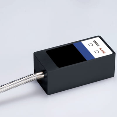
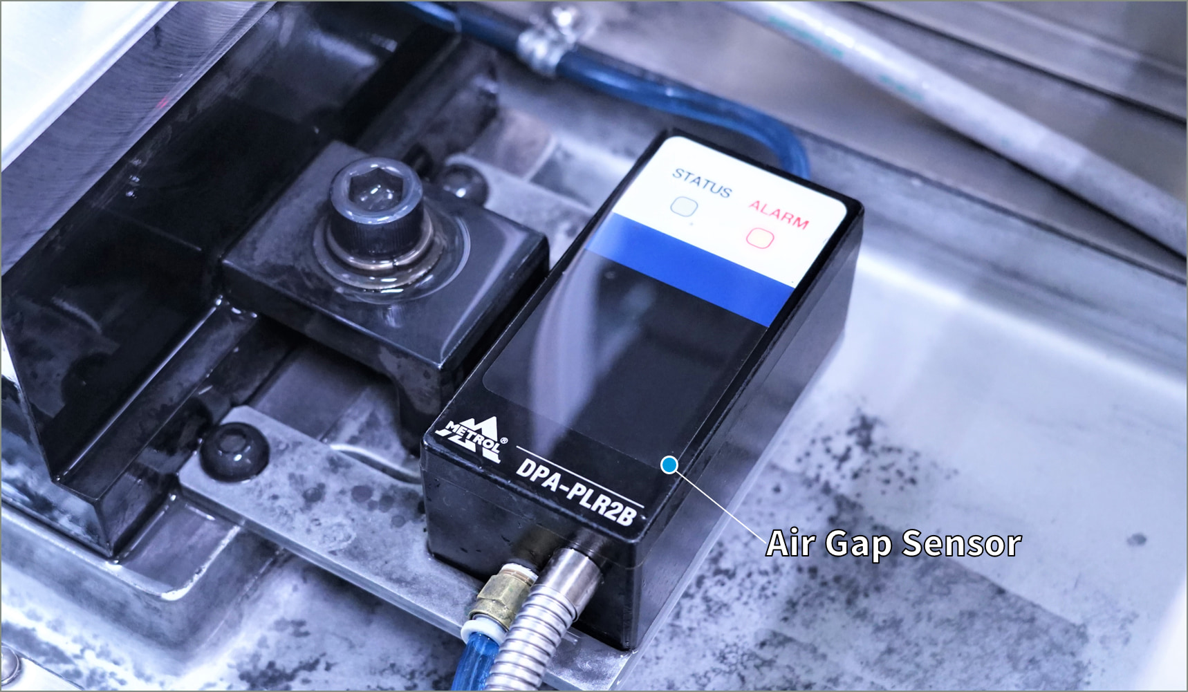
Air Gap Sensor DPA-PLR2B Series
Automated grinding wheel detection on NC grinders
Inquiries on requirements for introducing NC grinding machine automation.
Our engineers will answer your questions on NC grinding machine automation.
Contact us for support.