[Cautions when Using Sensors] Common Malfunctions, Causes & Countermeasures
Although METROL inspects all products before shipment, there are cases where products are returned due to malfunctions caused by incorrect usage.
The following table summarizes the most frequently occurring failures and their causes for all products.
| Description of Failure | Causes of failure |
|---|---|
| LED does Not come on or conduct | Over current |
| Decrease in accuracy and product life | 1. Contacting part is returned violently. 2. Contacting part is applied diagonally to the work piece. |
| Accuracy is not stable. | Low rigidity of jig |
| Cable disconnection / breaking of cable sheath | 1. Bending below minimum bend radius 2. cutting chips break the cable sheath. 3. Pull the cable hard. |
| Disconnection trouble when installing sensor | Pulling the cable / Cable bending beyond specified bending radius |
This article will discuss the causes of each of these failures and their countermeasures.
Target Products: Touch switch, Tool setter, Touch probe, Air-gap sensor
Table of Contents
Failure details, causes & countermeasures
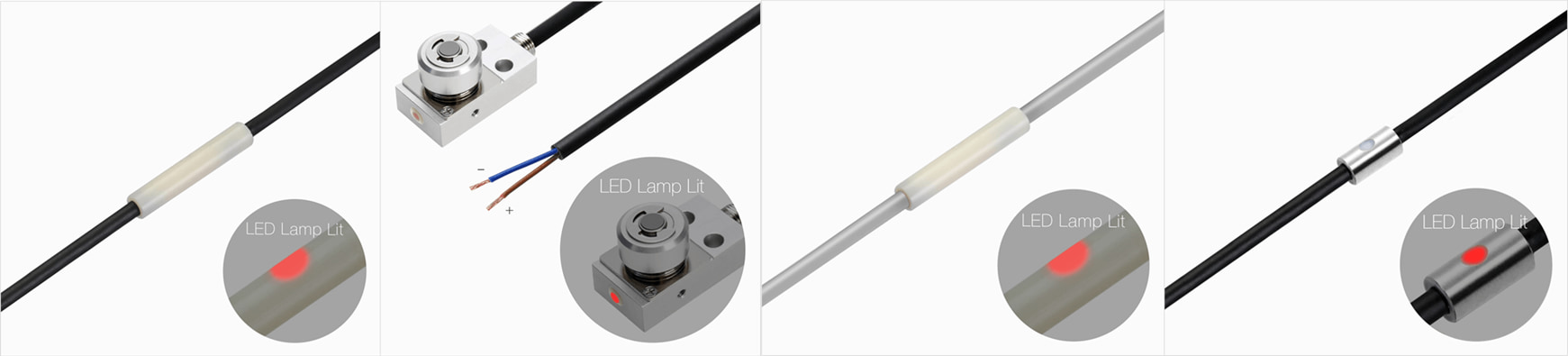
1. LED does Not come on or conduct
Causes of failure: Over current
The most common cause of failure, such as "LED does not light" or "sensor does not conduct," is "overcurrent.
For example, even when connected at the specified contact rating, a current greater than the rating may flow when the equipment is turned on. This is one cause of overcurrent, called inrush current.
By overcurrent,
- LEDs burn out and the switch will not conduct.
- Sparks (arcs) fly and fouling the switch contacts.
Both of these problems lead to a reduction in accuracy and product life, so it is important to take countermeasures.
Situations where overcurrents are likely to occur
Be careful of overcurrent in the following situations.
- When the device is turned on
- When acceptance testing was done (using a high voltage tester)
Since both occur before the product is used, they are often misidentified as initial defects.
Countermeasure for overcurrent: Use an I/F unit (interface unit)
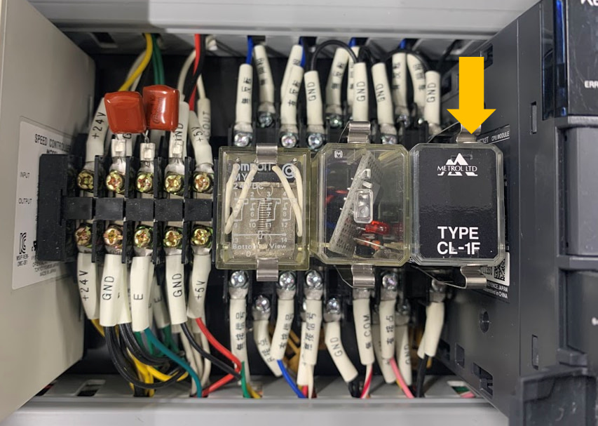
To reduce the effects of overcurrent, METROL recommends the use of an I/F unit (interface unit ).
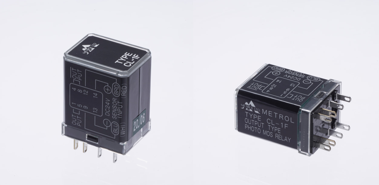
By installing the interface unit in the control panel in advance, it plays the role of a contact protection circuit in environments where there is a risk of overcurrent.
Advantages of I/F Unit
Unit use offers the following advantages
- Contact protection against overcurrent
- Output current can be increased
- Signal conversion available
- Extended contact life
- Gain in accuracy
The above advantages reduce the frequency of breakdowns, resulting in cost savings.
Countermeasures other than I/F unit
As for the touch switch, the same effect as the I/F unit can be achieved by incorporating the transistor option into the switch.
Reference Articles: Explanation of Transistor Functions
Checklist before using the products
- Take steps to prevent inrush currents from occurring
- Use I/F unit or transistor options
2.Reduced accuracy and contact life
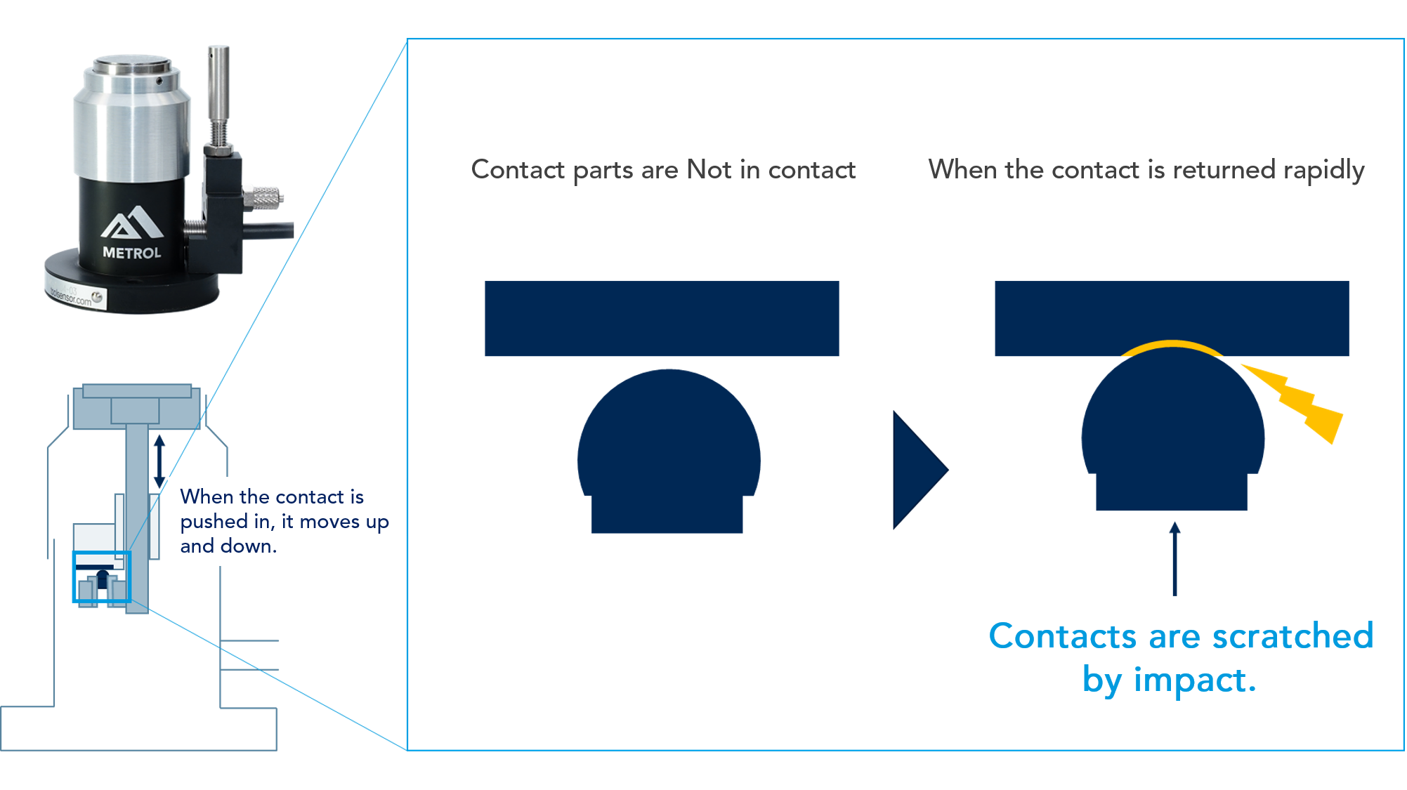
Cause1. Contacting part is returned violently.
Please refrain from snapping your fingers on the tool setters and touch switch contacts, as this action directly leads to malfunction.
Countermeasure for Cause 1: Do not flick the contact point vigorously.
・Do not pop the contact vigorously when returning it to its original position from being pushed in.
・Do not wipe forcefully or manually push contacts into the sensor in an attempt to clean it.
If the contacts are moved violently, the recoil causes dents in the internal contacts (Figure 1), reducing accuracy and contact life.
Common NG behaviors
- During installation, the contacts are pressed vigorously as a check of operation.
- Air dusters are applied directly to contacts during cleaning.
Checklist before using the products
- Do not pop contacts with fingers during installation or cleaning
- Do not spray air dusters directly on contacts when cleaning.
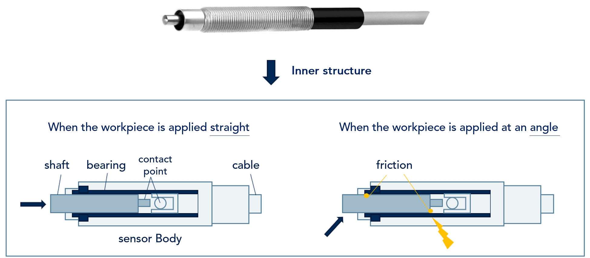
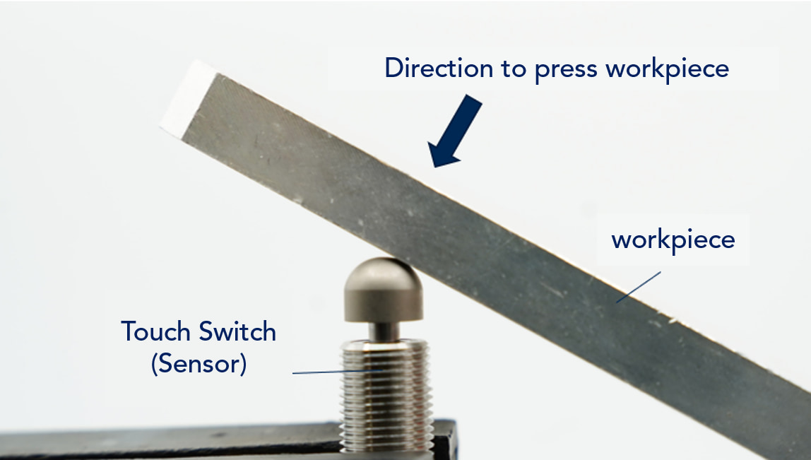
Cause2. :The workpiece is applied diagonally to the dedicated touch switch that applies the workpiece from the straight direction.
Applying the workpiece to the touch switch contacts in the wrong direction will accelerate product deterioration and lead to reduced accuracy and contact life.
When using a touch switch that applies a workpiece from a straight direction, if the sensing element is applied at an angle to the switch, the internal shaft will be subjected to oblique force. As a result, the shaft will rub against the workpiece, resulting in poor motion. (Figure 2)
Countermeasure for Cause 2: Check how the detector is applied.
Check the direction of movement of the touch switch and workpiece in advance, and adjust the touch switch so that it is applied in a manner suitable for the touch switch to be used.
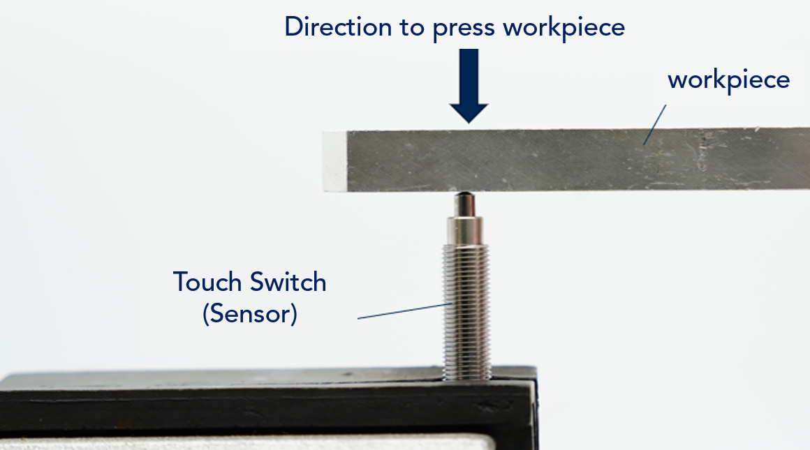
How to apply workpiece: What is "Straight Touch"?
The axis of the touch switch and the ground plane of the workpiece are perpendicular.
How to apply workpiece :What is "Angled or Sliding Touch" ?
Angled Touch: The axis of the touch switch and the ground surface of the contact each other in an oblique direction
Sliding Touch: Slide the sensing element to make contact with the sensor
*The touch switches dedicated for sliding and angled touch can also be used for straight.
Checklist before using the products
- Check at what angle (straight or diagonal) the detection body hits the touch switch.
- Adjust the mounting jig so that the sensing element contacts the sensor at the recommended angle.
- (For diagonal direction) Select a dedicated touch switch for sliding and angle.
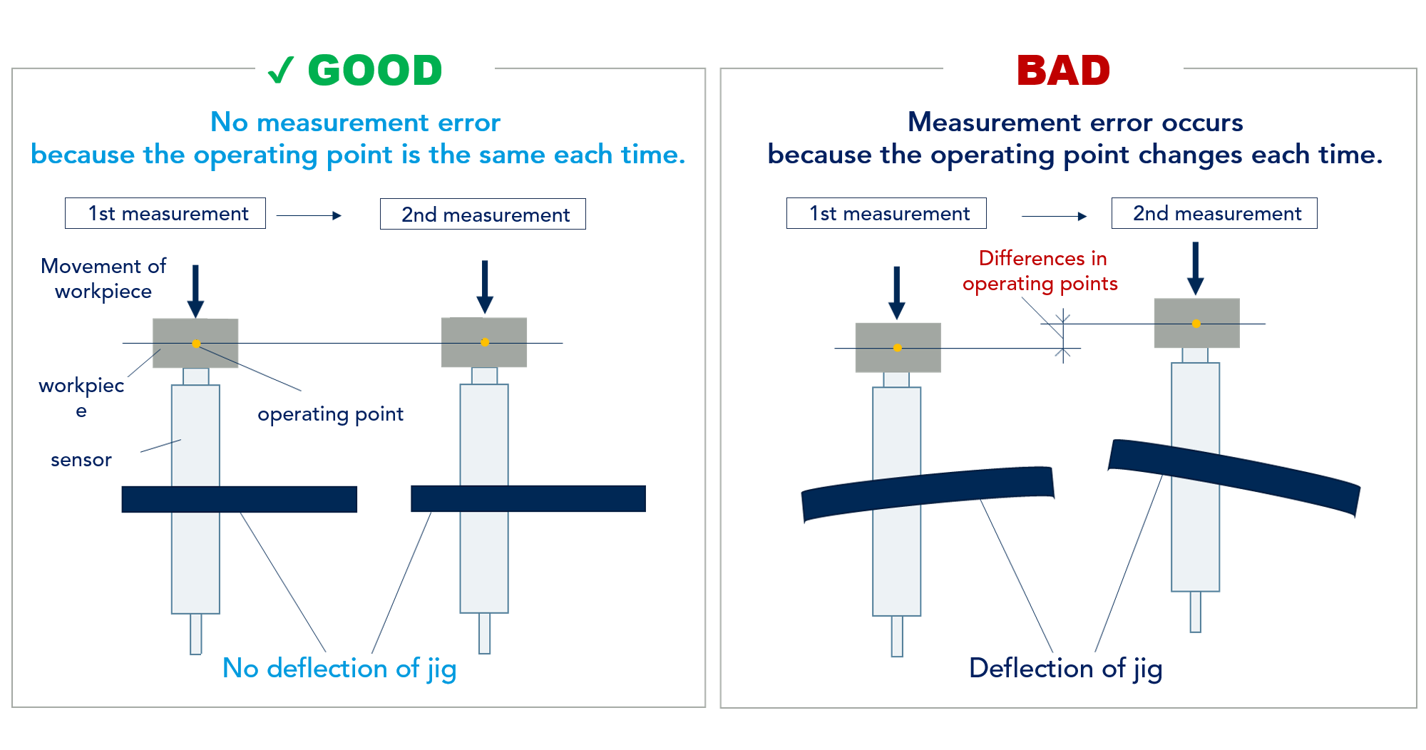
3.Accuracy is not stable
Cause: Low rigidity of jig
When sensor accuracy is unstable, the rigidity of the mounting jig often affects the accuracy.
If the jig that holds the sensor in place is soft, the contact force will cause the jig to deflect. If the jig is deflected, the operating point will vary each time contact is made, resulting in less repeatability of accuracy than specified.
Countermeasure: Use a rigid jig.
Check the rigidity of the jig beforehand and select a material that will not deflect when force is applied.
Relation between jig rigidity and accuracy
Checklist before using the products
- Mount the sensor on a mounting jig with sufficient rigidity.
4. Cable disconnection / breakage of cable sheath
The following are three common trouble factors related to cables.
1. Bending below minimum bend radius.
2. Cable sheath torn by chips.
3. Pull the cable.
Cause1 : Bending below minimum bend radius.
Bending a cable with a bending radius smaller than the specified value may cause the sheath to tear and the internal core wire to break.
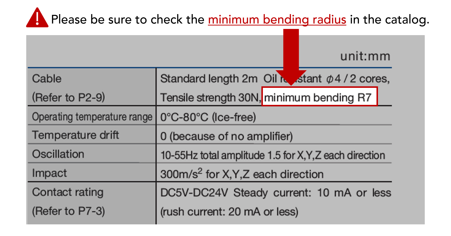
What is bending radius (bending R)?
The radius from the point of bending to the center of the bend when a bar or metal is bent.
Countermeasure for Cause 1: Allow the cable to bend greater than the minimum bend radius
When bending the cable, adjust the wiring so that the bend is greater than the minimum bend radius.
Check the type of cable and wire the cable so that the minimum bend radius is greater than the following.
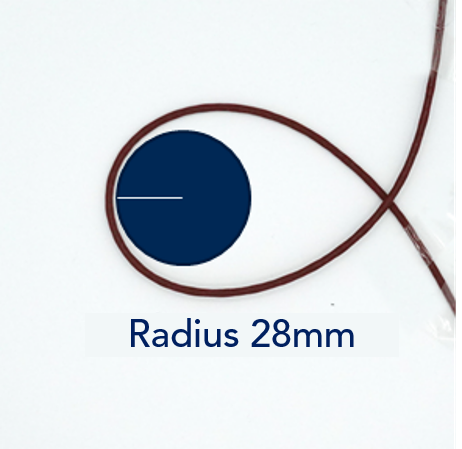
Minimum bending radius: R28
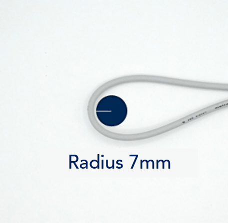
Minimum bending radius: R7
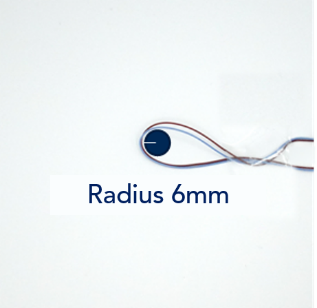
Minimum bending radius: R6
Cause2: Cable sheath torn by chips.
Metal chips generated in the operating environment can tear the cable sheath.
A tear in the cable sheath is not only a wire break, but also a risk of coolant ingress. Coolant can penetrate through the cable and induce shorts and contact failures.
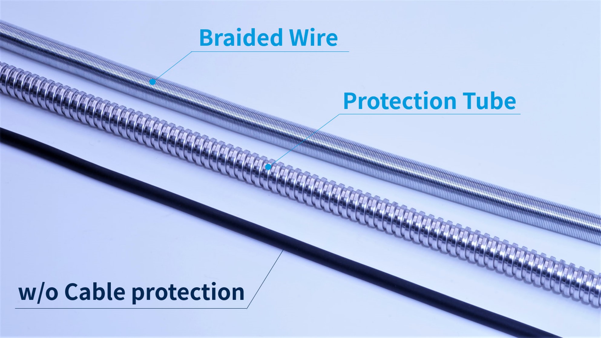
Countermeasure for Cause 2: Select cable protection options
If the environment in which the sensor is used may cause the cable sheath to break, please consider the following cable protection options
Reference Articles: Cable protection options
Checklist before using the products
- Allow the cable to bend greater than the minimum bend radius
- Select cable protection options
5. Disconnection trouble when installing sensor
Cause: Pulling the cable / Cable bending beyond specified bending radius
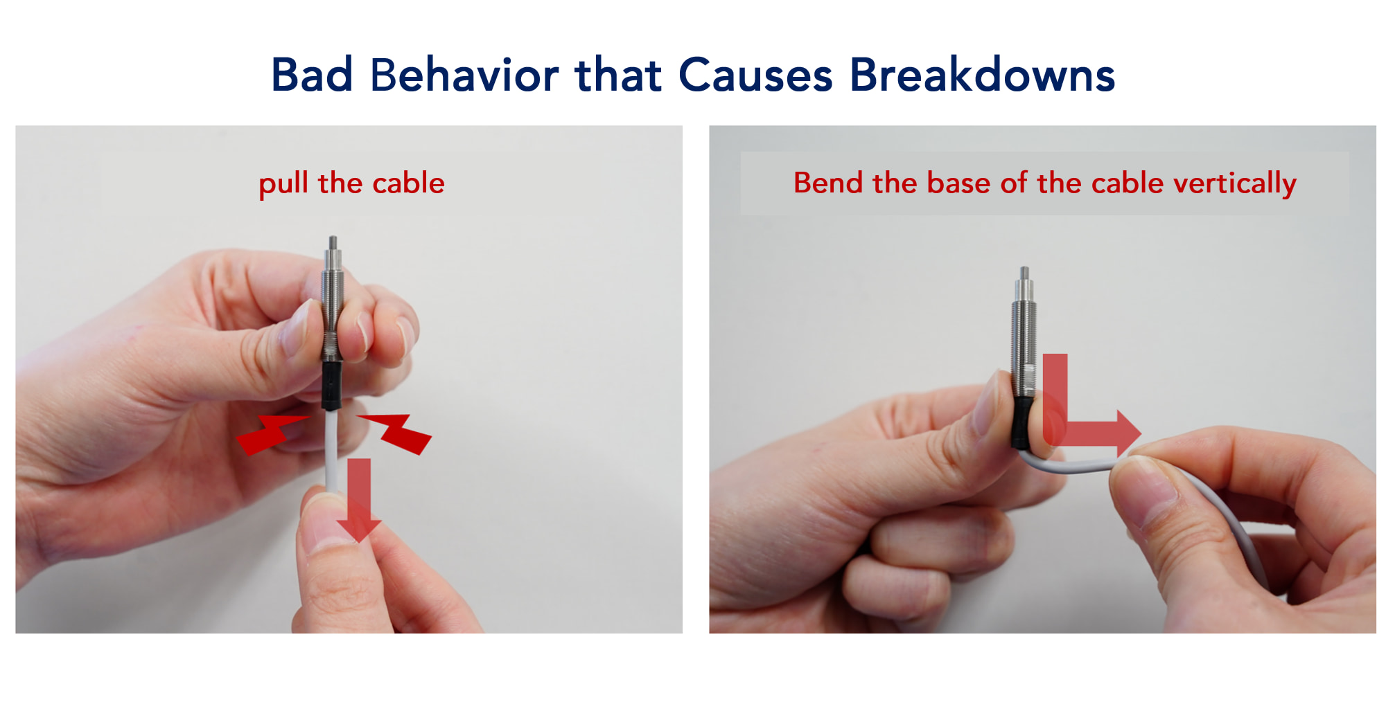
When wiring the sensor cable to the device, the following causes have been reported to break the insulation inside the switch, rendering it unusable.
- Pull hard on the base of the cable.
- Cable bending beyond specified bending radius
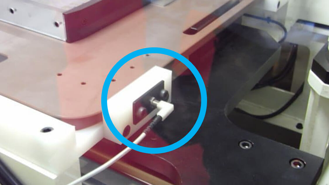
In particular, since heat-resistant products use cables that are difficult to bend, be sure to observe the bending radius (R) specified in the catalog.
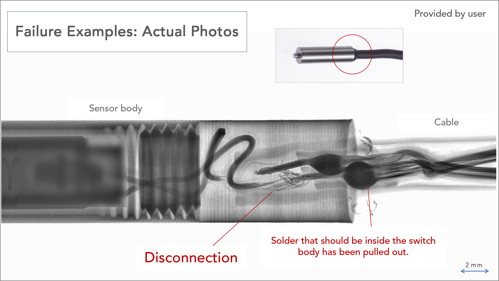
The photo above is an x-ray of the actual failed product. (Courtesy of user)
The cable was pulled so hard that it broke internally, causing solder that should have fit into the switch to protrude to the outside.
Please take the following measures to prevent cable breakage.
Countermeasure 1: Observe the cable bending radius (R) with wiring with sufficient length.
・Wiring should be made to fit within the "minimum wiring cord bending radius" specified in the catalog.
・Consider the sensor mounting position so that the cable is not pulled strongly or bent below the bending radius.
・Specify a longer cable at the time of purchase.
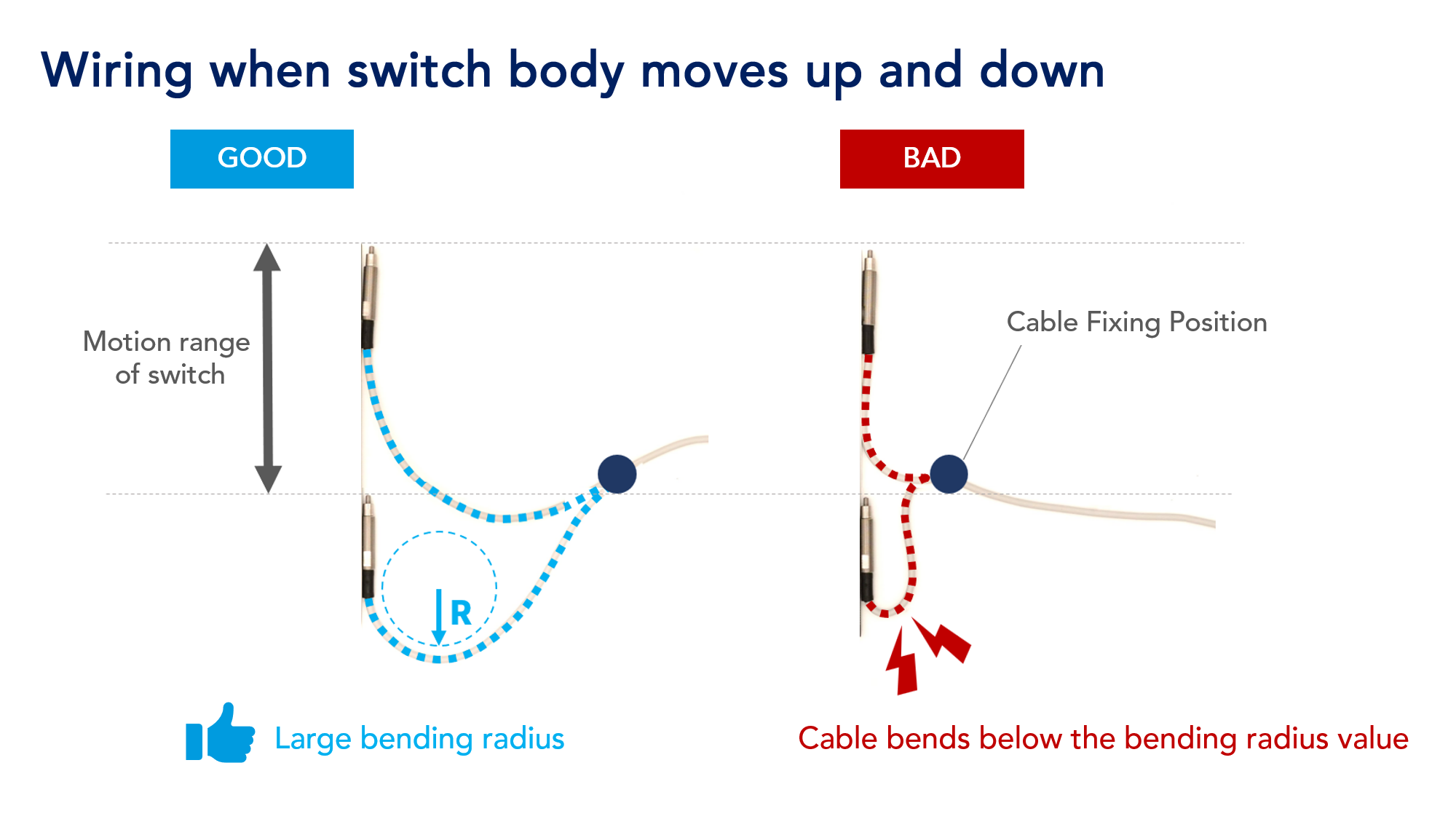
When mounting the switch on a moving device such as a robot arm, the switch's range of motion should be considered and wired so that the bending radius value is always secured.
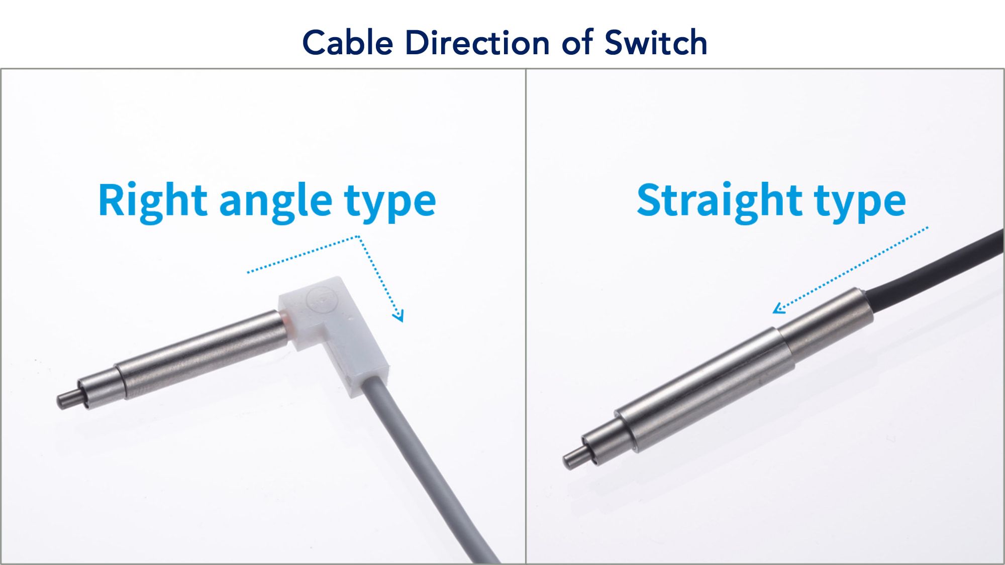
Countermeasure 2: Consider changing cable direction.
METROL sensors can change the cable direction from normal straight to right-angle.
Changing the cable direction allows wiring in locations where mounting is difficult.
We recommend using a right-angle cable depending on where the sensor is mounted.
Checklist before using the products
- Install the sensor with plenty of room for the length of the cable.
- Do not pull on the sensor and cable connections.
- Check the bend radius of the cable
Conclusion
Correct use of sensors and switches maintains accuracy and enables higher precision manufacturing.
It also creates cost advantages due to its extended life span.
Before using a sensor, be sure to check the following points.
| Description of Failure | Causes | Countermeasures |
|---|---|---|
| LED does Not come on or conduct | Over current | Use an I/F unit (interface unit) |
| Decrease in accuracy and product life | 1. Contacting part is returned violently. 2. Contacting part is applied diagonally to the work piece. | 1. Do not flick the contact point vigorously. 2. Check the direction in which the detector strikes the sensor. |
| Accuracy is not stable. | Low rigidity of jig | Use a rigid jig. |
| Cable disconnection / breaking of cable sheath | 1. Bending below minimum bend radius 2. cutting chips break the cable sheath. 3. Pull the cable hard. | 1. Observe the cable bending radius (R) with wiring with sufficient length. 2. Consider changing cable direction. |
We recommend that this article be disseminated not only to the purchasing and design departments, but also to those who actually use the equipment.
We would appreciate it if you could circulate this article within your company or print it out and place it at your work site.
Feel free to contact us
Use our contact form below to contact us.