What Is Geometric Tolerance?
Before we dive into geometric tolerances, let’s quickly review the overall types of tolerances. In general, tolerances can be broadly classified into the following four categories.
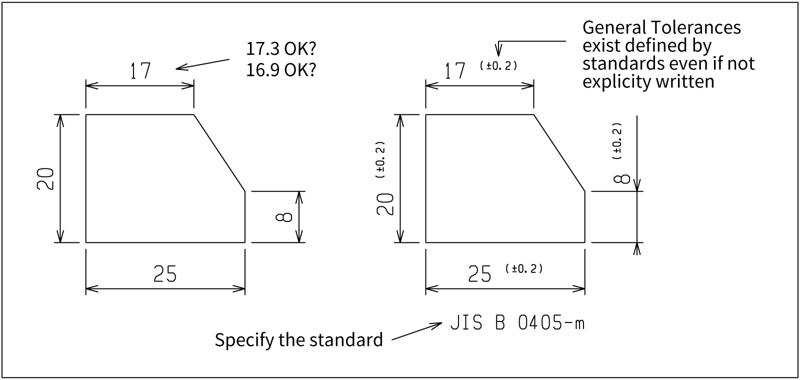
- General Tolerances (Default Tolerances)
This is a scheme in which standard allowable deviations are applied collectively to dimensions that do not have individual tolerance specifications on the drawing.
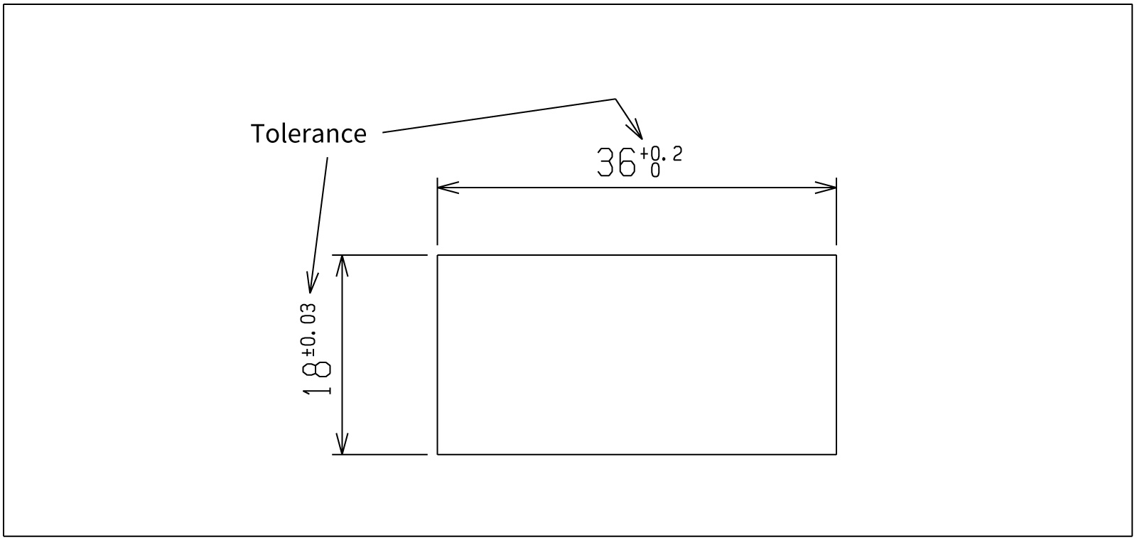
- Dimensional Tolerances (Size Tolerances)
These specify the permissible range for a part’s “size,” such as length or diameter, and are indicated individually in forms such as “10 ± 0.1 mm.”
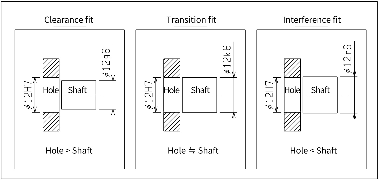
- Fit Tolerances
A type of dimensional tolerance that represents the fit between a hole and a shaft. By combining a hole symbol (e.g., H7) and a shaft symbol (e.g., g6), the actual clearance or interference is determined.
- Geometric Tolerances
Tolerances used to control a part’s form, the positional relationships of axes and surfaces, and runout during rotation. They use dedicated symbols to specify items such as “flatness” and “position.”
In this article, we explain “geometric tolerances,” one category of tolerances.
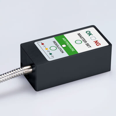
High-precision seating confirmation of workpiece and jig
- Air Gap Sensor -
You can check not only "presence/absence" but also "adhesion (gap)" at the same time with a repeatability of ±0.5 μm.
Click here ›Table of Contents
What Are Geometric Tolerances?
Geometric tolerances indicate the permissible deviations related to a part’s form, location, orientation, and runout-in other words, errors other than size.
To ensure functionality, assemblability, and interchangeability, they define strict requirements for each geometric feature.
Types and Classification of Geometric Tolerances
Geometric tolerances are broadly classified into four categories: form tolerances, orientation tolerances, location tolerances, and runout tolerances.
- Form Tolerances
Define how much distortion of the part’s “shape” itself is allowed.
Datum: Not required. For profile tolerances, a datum may be referenced as needed.
- Orientation Tolerances
Define what angle or direction a surface or axis must maintain relative to a datum-essentially controlling angular misalignment.
Datum: Required
- Location Tolerances
Define whether features (holes, grooves, shafts, etc.) are located as intended according to the basic dimensions, controlling X-Y offsets and concentricity/coaxial deviations.
Datum: Required
- Runout Tolerances
Define wobble (runout) when a part rotates. This is a rotation-specific control item in which size, form, and location interact in a complex manner.
Below is a list of geometric tolerances grouped into these four categories.
| Category | Name | Meaning of the Tolerance Zone (Key Point) | Symbol / Unicode |
|---|---|---|---|
| Form Tolerances |
Straightness |
Surface: In each cross-section, all points lie between two parallel lines separated by distance t. Axis: The axis line lies within a coaxial cylinder of diameter t. |
— |
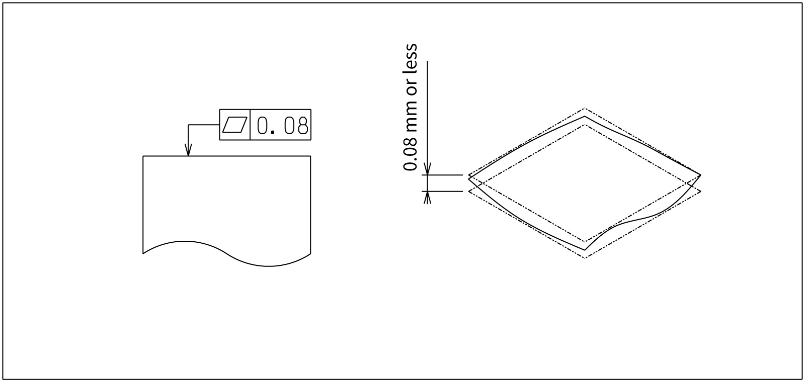
| Flatness | The surface lies between two parallel planes separated by distance t. | ⏥ / U+23E5 | |
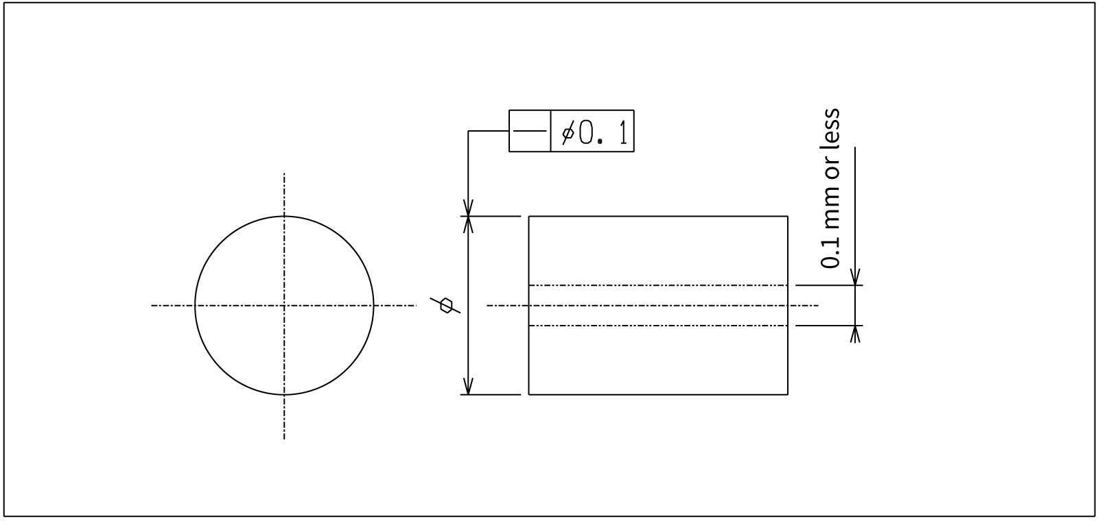
| Circularity (Roundness) | In any cross-section perpendicular to the axis, the profile lies between two concentric circles (radius difference t/2, diameter difference t). | ○ / U+25CB | |
| Cylindricity | The surface lies between two coaxial cylinders with a radius difference of t/2 (diameter difference t). | ⌭ / U+232D | |
| Profile of a Line | The actual line lies within a zone bounded by equidistant lines of total width t centered on the true profile. | ⌒ / U+2312 | |
| Profile of a Surface | The actual surface lies within a zone bounded by equidistant surfaces of total width t centered on the true profile. | ⌓ / U+2313 | |
| Orientation Tolerances |
Parallelism |
Surface: The surface lies between two planes parallel to the datum plane, spaced t apart. Axis: The axis line lies within a cylinder of diameter t parallel to the datum (cylindrical zone). |
∥ / U+2225 |
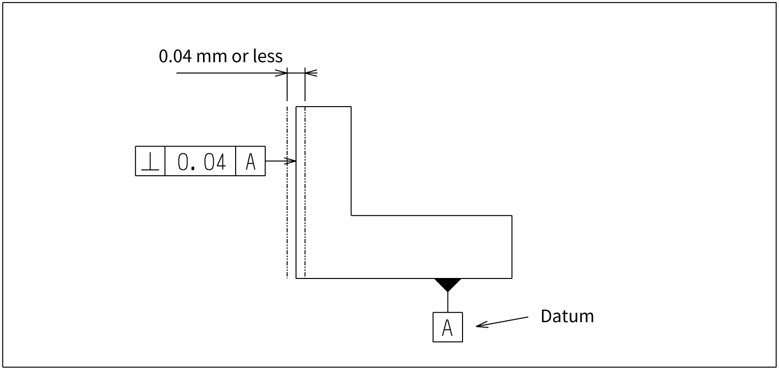
| Perpendicularity |
Surface: The surface lies between two planes at 90° to the datum plane, spaced t apart. Axis: The axis line lies within a cylinder of diameter t perpendicular to the datum plane (cylindrical zone). |
⟂ / U+27C2 | |
| Angularity |
Surface: The surface lies between two planes inclined at the basic angle to the datum, spaced t apart. Axis: The axis line lies within a cylinder of diameter t inclined at the basic angle to the datum. |
∠ / U+2220 | |
| Location Tolerances |
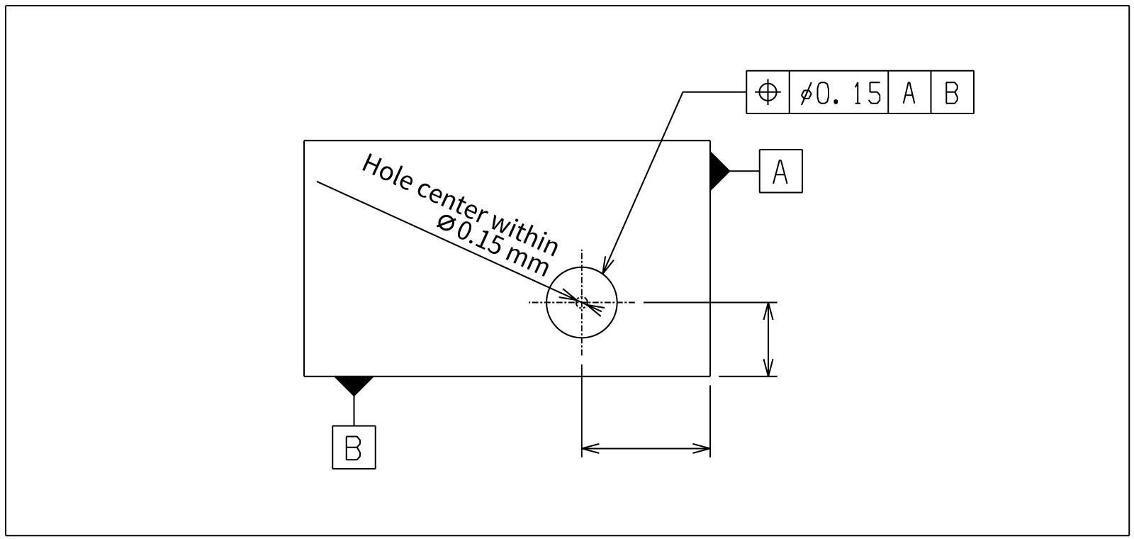
Position |
With “Ø”: The center axis lies within a cylinder of diameter t (3D cylindrical zone). Without “Ø”: The center point lies within a square with diagonal t (in the plane). Position tolerances can be applied to any theoretical feature, such as planes, spheres, or cylinders. |
⌖ / U+2316 |
| Concentricity / Coaxiality |
Concentricity: The center point of each cross-section lies within a circle of diameter t concentric with the datum axis. Coaxiality: The entire center axis lies within a cylinder of diameter t coaxial with the datum axis. |
◎ / U+25CE | |
| Symmetry | The median plane (or line) lies between two planes equally disposed at ±t/2 from the datum plane (total separation t). | ⌯ / U+232F | |
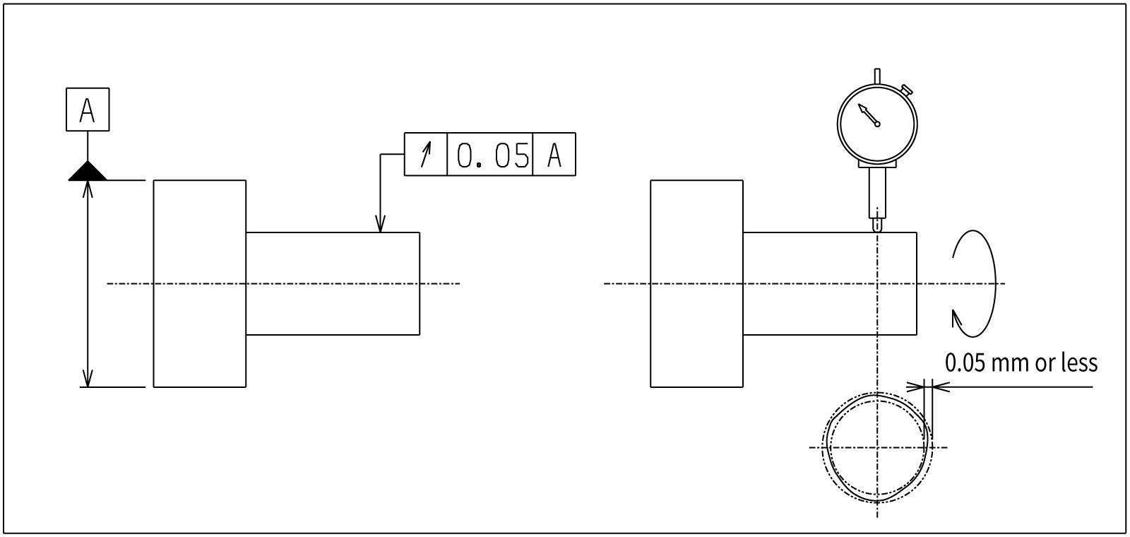
| Runout Tolerances |
Circular Runout |
When the part is rotated one revolution, the runout indicated by the measuring probe (maximum − minimum) is t or less. Cylindrical surface: Measures radial (diameter-direction) runout. End face: Measures axial (face-direction) runout. |
↗ / U+2197 |
| Total Runout | While rotating the part, the probe is also moved along the axis, and the total indicator reading (TIR) runout is t or less → a 3D tolerance controlled over a cylindrical total zone (entire length + 360°). | ⌰ / U+2330 |
Automates originating of cutting tools
- Tool Setter -
Tool length and chips are monitored to prevent machining defects due to wear and thermal displacement
Click here ›How to Specify Geometric Tolerances on Drawings
When indicating geometric tolerances on a drawing, you use a rectangular box called a feature control frame (tolerance frame).
For example, when specifying a hole’s position tolerance as a ⌀0.05 tolerance zone relative to datum surfaces A, B, and C, you would write something like “⌖ | ⌀0.05 | A | B | C” in the feature control frame, and connect the leader from the frame to the hole dimension or the diameter dimension line.
This indicates that “the hole’s axis must lie within a cylinder of diameter 0.05 relative to datums A, B, and C.”
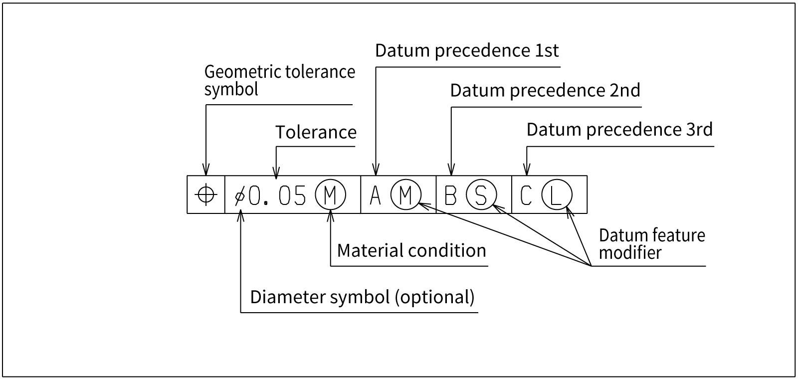
The following elements are entered in the feature control frame in order.
1.Geometric Characteristic Symbol
Write the symbol for the specified geometric tolerance in the leftmost compartment. This indicates which type of geometric deviation is being controlled.
2.Diameter Symbol (When Required)
If the tolerance zone is defined by a diameter, add “⌀” before the tolerance value. This applies, for example, when controlling a hole’s position with a cylindrical zone, or when controlling an axis’s straightness or parallelism with a cylindrical zone.
3.Tolerance Value
Enter the allowable amount of deviation as a numerical value. The unit is the drawing’s length unit (typically mm) and is often omitted. If necessary, add notes about form or direction after the value (e.g., “± symmetrically”).
4.Modifiers / Additional Symbols
Add condition symbols related to the tolerance value as needed. Typical examples include “Ⓜ” to indicate maximum material requirement, “Ⓛ” for least material requirement, and “ⓔ” to indicate the envelope requirement (perfect form envelope by a cylinder or two parallel planes). In ISO/JIS, there is also a rule to add “UZ” when the tolerance zone is asymmetric (unequally disposed).
5.Datum References
For orientation, location, and runout tolerances, enter the datum references on the right side of the feature control frame. When using multiple datums, list them in order of precedence (e.g., A | B | C). If needed, add “Ⓜ,” “Ⓛ,” etc. after each datum symbol to specify that the datum is to be applied at maximum or least material condition.
What Can Happen If You Don’t Specify Geometric Tolerances Accurately
If only dimensional tolerances are specified when outsourcing machining, there is still a possibility — however unlikely — that a part like the one shown below could be delivered.
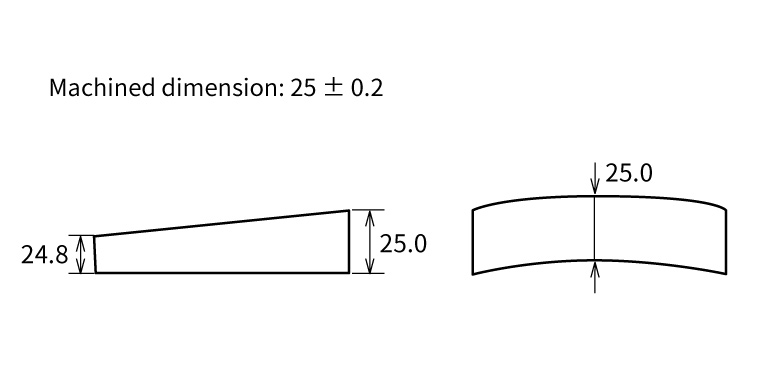
With size tolerances alone, even such a part may pass inspection.
If the part is machined domestically, the machinist may interpret the designer’s intent and achieve “flatness” and “parallelism.”
However, it cannot be said with certainty that no supplier would deliver a problematic part simply because “the dimensions are within tolerance.” Even if it feels like extra work, be sure to specify geometric tolerances as well.
Especially when outsourcing to a supplier for the first time, we recommend specifying slightly tighter size tolerances together with geometric tolerances.
Build the Habit of Adding Geometric Tolerances to In-House Manufacturing Drawings
Make it a habit to include geometric tolerances even on drawings for parts used in in-house jigs and fixtures.
For parts completed entirely in-house, it is common to rely on only a simple sketch and dimensions. As a result, there are workplaces where operators machine parts without knowing geometric tolerances.
Drawings that include only a figure and dimensions do little to improve operators’ skills or machining knowledge. Geometric tolerances are something machinists and operators should learn.
Ensure Even Load/Unload Operators Understand Geometric Tolerances
The people who should understand geometric tolerances are not limited to designers, setup personnel, and machinists.
In recent years, more companies have assigned the loading and unloading of mass-produced parts to part-time or temporary staff. It is advisable to ensure that such “load/unload-only operators” are also familiar with geometric tolerances.
One reason is that when tool wear causes chatter marks on the machined surface, operators who are unaware of geometric tolerances such as “flatness” and “parallelism” may continue loading/unloading and machining, potentially producing a large number of defective parts.
If operators understand geometric tolerances, they can judge “this part is defective” as soon as chatter appears, enabling decisions such as stopping the process and thereby minimizing losses.
What Are Metrol’s High-Precision Positioning Sensors?
So far, we have covered an overview of geometric tolerances and their types. In real manufacturing environments, there are many situations where highly accurate measurement and positioning are required to maintain dimensional accuracy.
As one effective way to meet these high-precision needs, we introduce METROL’s high-precision positioning sensors.
High-Precision Positioning Touch Switches
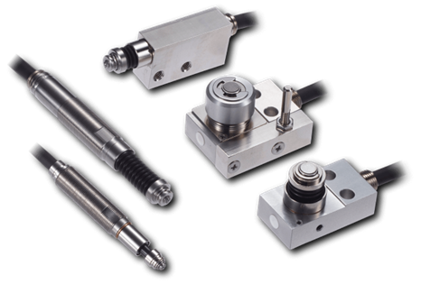
These are contact-type high-precision switches used for positioning and workpiece presence detection in machine tools, robots, and jigs. They achieve an extremely high repeatability of up to 0.5 µm and feature IP67-rated waterproof and dustproof protection, ensuring stable operation even in harsh environments. With more than 200 standard models available, they offer a wide range of variations, including designs for confined spaces, high-temperature environments, vacuum applications, and low contact force requirements.
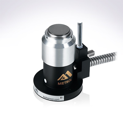
Tool Setter (Tool Length Measurement Sensor)
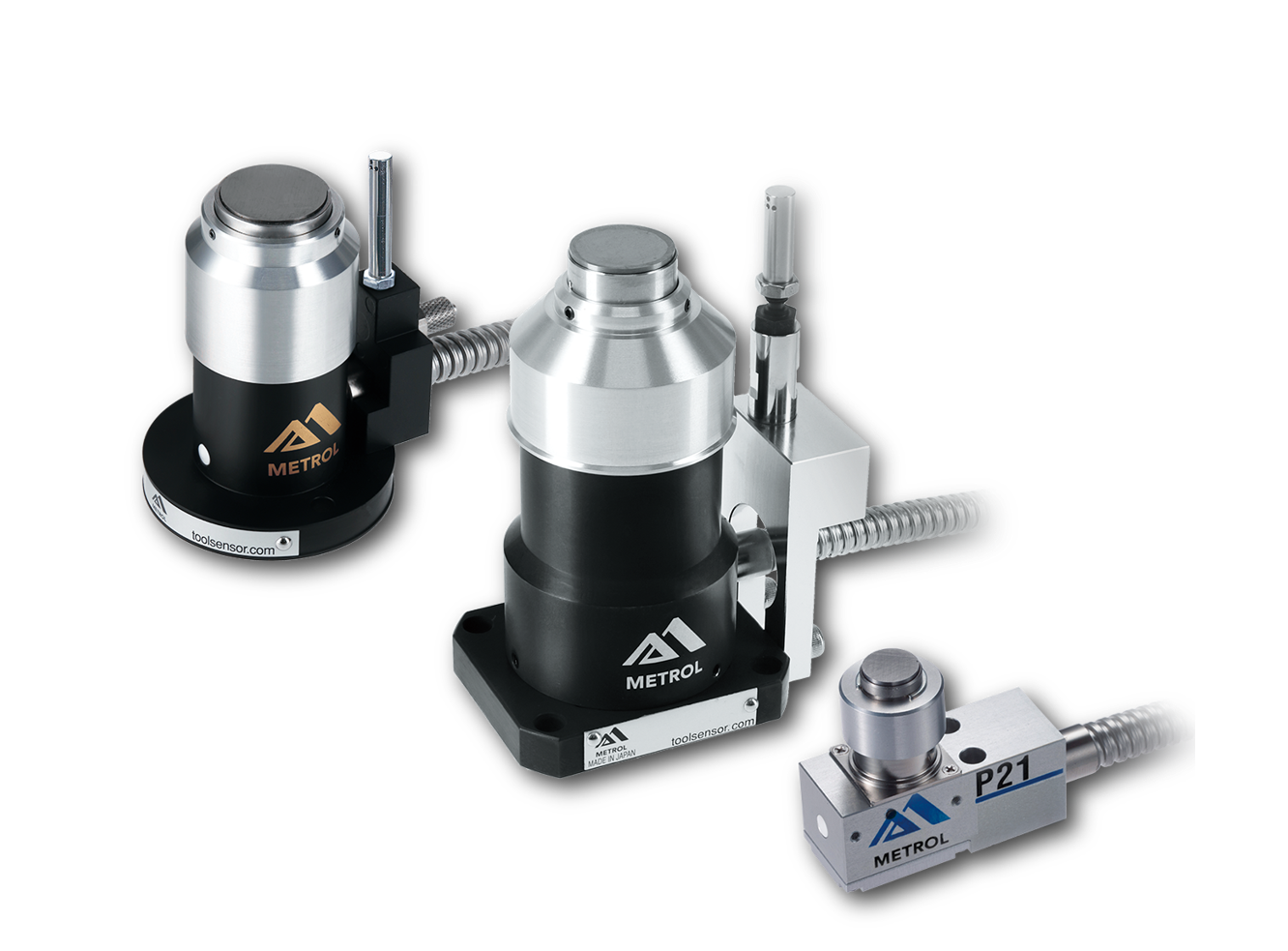
This is a contact-type sensor installed on CNC machine tools and industrial robots for tool length measurement, reference position setting, and tool breakage detection. By automatically measuring and compensating for tool length, wear, and thermal displacement inside the machine, it helps prevent machining defects and significantly reduces setup time. It is one of Metrol’s best-selling products, with a proven track record of more than 500,000 units shipped in 74 countries worldwide.
Touch Probe (On-Machine Measurement Probe)
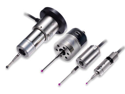
This is a contact-type probe for in-machine measurement, installed on machine tools and robots to automatically perform workpiece positioning (centering) before machining and dimensional measurement after machining. With a repeatability of 1 µm, it automates workpiece referencing and dimensional inspection, replacing skilled manual operations to reduce setup time and help prevent machining defects. Both wired and wireless models are available, meeting retrofit needs for 5-axis machining centers and robotic applications.
Air Gap Sensor (Pneumatic Sensor)
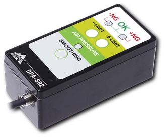
This is a non-contact sensor that uses air pressure to detect workpiece seating conditions with micron-level accuracy. It can detect gaps (“lift”) of less than 10 µm—previously difficult to measure—with a repeatability of ±0.5 µm, helping prevent machining defects and equipment downtime caused by insufficient contact between the workpiece and fixture. The sensor is used in applications such as semiconductor manufacturing processes, precision part clamping operations, and grinding wheel positioning on grinding machines, and it is a smart sensor that also supports the international standard IO-Link communication.