What Is a Micrometer? From Basics to Measurement Procedures
A micrometer is a precision measuring instrument used to accurately measure outside diameters and thicknesses with micron-level resolution.
In this article, we clearly explain its basic structure and measurement procedures, as well as the differences between micrometers, calipers, and dial gauges. We also introduce the latest measurement solutions, including high-precision sensor technologies.
Table of Contents
What Is a Micrometer?
A micrometer is a measuring tool designed to accurately measure the outside diameter, thickness, and other dimensions of an object by using a precise screw mechanism. The workpiece is placed between the frame, and the dimension is read based on the minute axial movement of the spindle (measuring shaft) caused by the rotation of the screw.
In a typical analog micrometer, the screw pitch (the distance between thread peaks) is set to 0.5 mm, meaning that the spindle advances by 0.5 mm for each full rotation of the thimble, which is the rotating part with engraved graduations.
By utilizing the relationship between the rotation angle and the linear movement, the scale divides one full rotation into 50 equal parts, allowing measurements to be read in increments of 0.01 mm. This mechanism makes it possible to measure extremely small lengths that cannot be resolved by the naked eye.
The minimum scale value of a micrometer is generally 0.01 mm for analog models, while digital micrometers typically offer a resolution of 0.001 mm (1 µm).
Considering that the thickness of a typical sheet of copy paper is about 0.09 mm, it becomes clear just how precise micrometer measurements can be.
Differences Between Micrometers and Other Measuring Instruments (Calipers, Dial Gauges, etc.)
Other common measuring instruments with similar applications to micrometers include calipers and dial gauges.
Comparison with Calipers
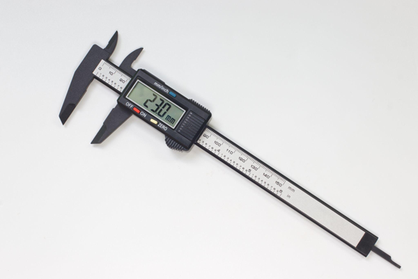
Calipers (general digital and analog calipers) are versatile measuring instruments that allow direct measurement of various dimensions—such as outside diameter, inside diameter, step height, and depth—by sliding the main scale.
Due to their structural characteristics, calipers typically offer measurement accuracy of around 0.1 mm, with minimum scale divisions commonly set at 0.02 mm or 0.05 mm.
In contrast, micrometers require selecting a dedicated type according to the target measurement—such as outside, inside, or depth micrometers—but they are specifically designed to provide higher measurement accuracy than calipers.
Comparison with Dial Gauges
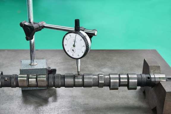
A dial gauge is a measuring instrument primarily used for comparative measurement and cannot measure absolute dimensions on its own, requiring a fixture such as a stand to hold it in place.
Dial gauges magnify minute axial displacements through the rotation of a pointer, making them suitable for measuring geometric tolerances such as runout and deformation in machinery.
These differences can be summarized as follows: while calipers and micrometers are instruments that directly read absolute dimensions, dial gauges are comparators with high resolution and repeatability, designed to measure deviations from a zero-set reference.
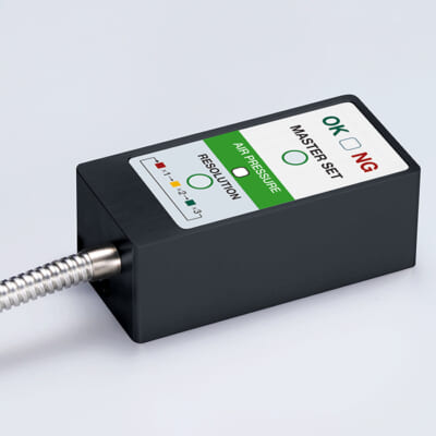
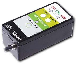
High-precision seating confirmation of workpiece and jig
- Air Gap Sensor -
You can check not only "presence/absence" but also "adhesion (gap)" at the same time with a repeatability of ±0.5 μm.
Click here ›Components and Structure of a Micrometer
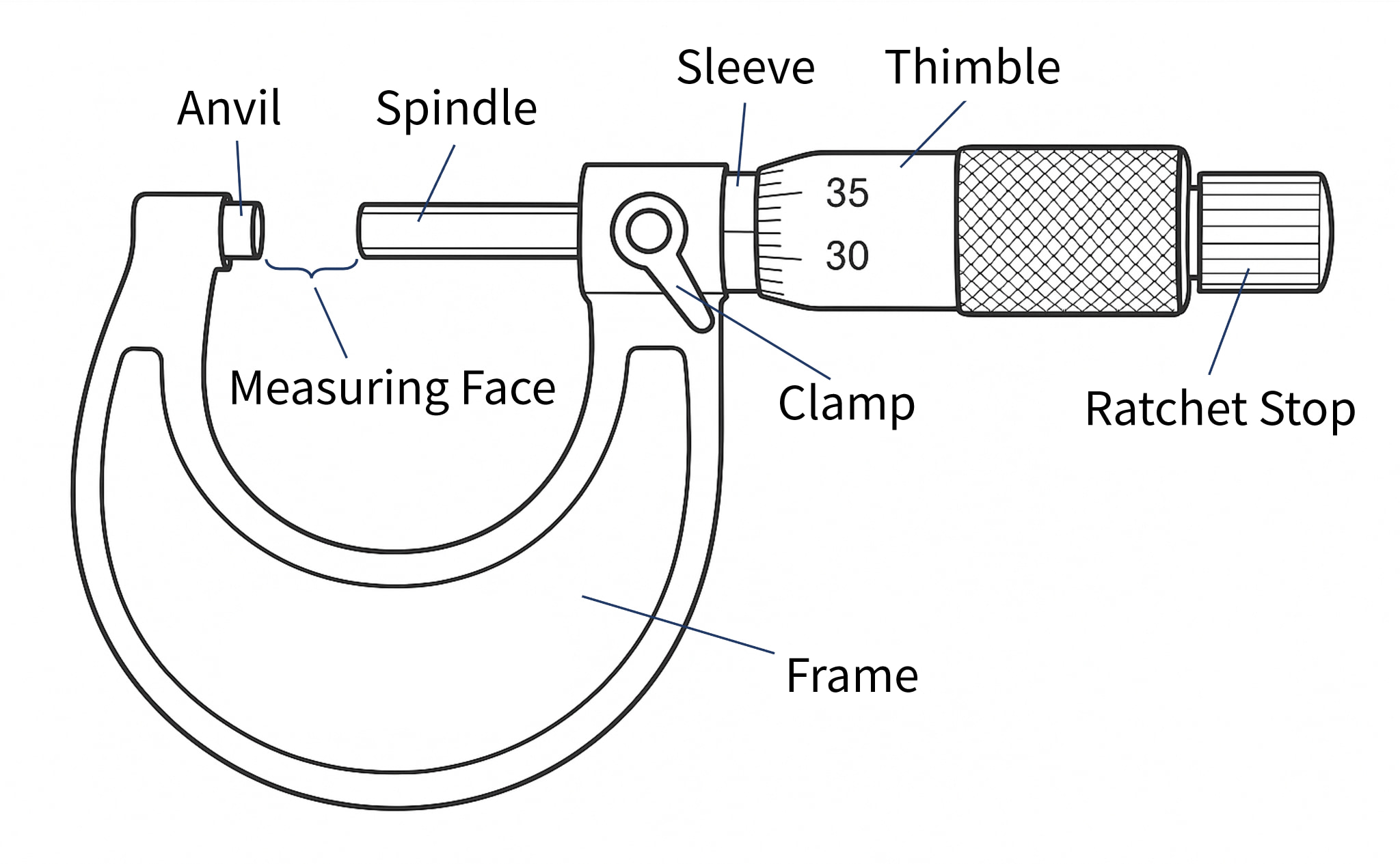
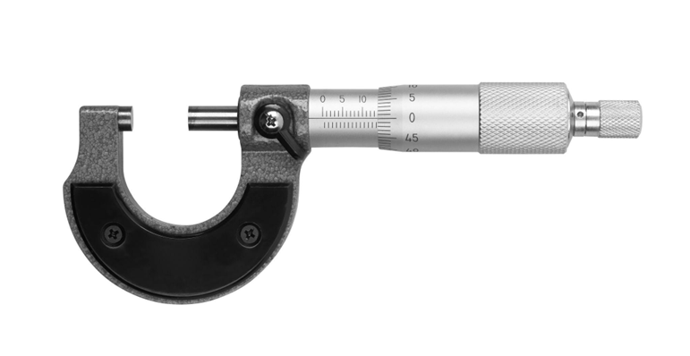
A micrometer has a seemingly simple structure, but it is composed of several components that enable precise measurement. Below, we explain the main components in particular.
| Components | Description |
|---|---|
| Anvil | The anvil is a flat, circular metal measuring surface fixed to the end of the frame, which comes into direct contact with the workpiece. |
| Spindle | The spindle is a movable shaft with a measuring surface that faces the anvil. It advances and retracts in the axial direction as the thimble is rotated. |
| Sleeve | The sleeve is a cylindrical section fixed to the frame, with evenly spaced main scale graduations (reference scale) engraved on its outer surface. |
| Thimble | The thimble is a rotating cylinder attached to the rear end of the spindle. Turning it with the fingers causes the spindle to move forward and backward. |
| Ratchet Stop | The ratchet stop is a small knob mounted at the end of the thimble. It slips with a clicking sound when rotated beyond a certain torque, ensuring a constant measuring force. |
Structural Characteristics
Micrometers are structurally designed to minimize Abbe error and cosine error. Based on Abbe’s principle, the scale axis and the measurement axis are aligned on a single straight line, which reduces the influence of angular deviation (cosine error) compared with sliding-type instruments such as calipers.
By measuring in the proper posture and using the ratchet stop, these structural accuracy advantages can be fully utilized.
Analog and Digital Types
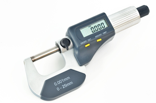
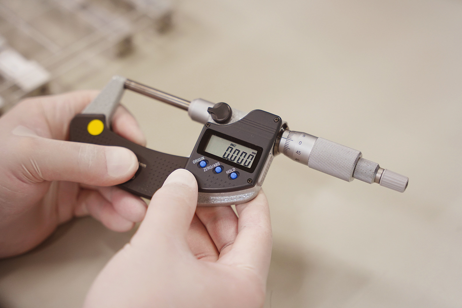
Micrometers are available in both traditional analog (mechanical) types and digital types that display measurement values on an LCD. While the basic structure is the same for both, and dimensions are measured by the spindle feed driven by a screw mechanism, the two differ in how measurement values are displayed.
The difference lies in how the measurement value is displayed. In an analog micrometer, the user reads the graduations on the sleeve and thimble manually. In a digital micrometer, by contrast, the displacement detected by the internal scale is counted electronically and displayed as a numerical value on an LCD (liquid crystal display).
For internal detection in digital micrometers, rotary encoders or linear scales are used, with the sensing method—such as electromagnetic or capacitive—varying by manufacturer. By converting the rotation angle of the thimble (or linear displacement) into electrical signals and processing them, digital micrometers achieve high-resolution measurement readings.
Measurement Units and Conversion
The dimensional units used with micrometers are mainly millimeters (mm) and micrometers (µm).
The unit conversions are as follows.
1mm = 1000μm
1μm = 0.001mm
One micrometer (1 µm) is an extremely small unit. Considering that the thickness of a human hair is approximately 80 µm, this helps illustrate just how fine a measurement 1 µm represents.
Values measured with a micrometer are usually reported in millimeters; however, micrometers may also be used when finer evaluation is required for quality control or when specifying tolerances.
For example, if a measurement result is 12.72 mm, this corresponds to 12,720 µm. Such values are often expressed in combination with tolerances, such as ±5 µm.
Calibration and Traceability
No matter how accurate a measuring instrument may be, reliable measurement results cannot be obtained unless it is properly calibrated. Calibration refers to the process of comparing the values indicated by a measuring instrument with those of a higher-accuracy reference standard in order to identify errors and make adjustments if necessary.
In the case of micrometers, calibration is typically performed using gauge blocks (length standards). Known lengths—such as 5 mm, 10 mm, 15 mm, and so on—are measured, and the differences between the indicated values and the reference lengths are checked.
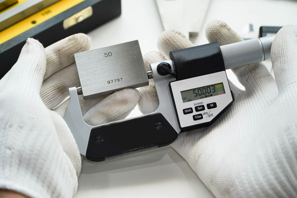
Through such calibration procedures, it is verified that the micrometer meets the specified accuracy requirements, thereby ensuring the reliability of the measurement results.
Especially in quality assurance applications, the traceability of measurement results is critical. By clarifying which reference standards were used to calibrate the measuring instrument, it can be demonstrated that the obtained dimensional values are reliably linked to national standards.
To ensure that measurement results are accepted internationally, the establishment of metrological traceability is essential.
Separate Gauge Blocks for Shop Floor Use and Calibration
Gauge blocks are very expensive, and for newly established companies or small machine shops, it is often difficult to maintain separate sets for shop floor use and for calibration purposes.
As a result, many companies use worn gauge blocks from the production floor directly for micrometer calibration.
From a quality assurance standpoint, this practice is not recommended and may lead to a loss of customer trust. To ensure reliable calibration and maintain credibility, dedicated gauge blocks for calibration should always be prepared and properly managed.
Store and Use Calibration Gauge Blocks in a Temperature-Controlled Inspection Room
Even if calibration gauge blocks are prepared, storing or using them on the shop floor where temperature fluctuations are significant defeats their purpose.
Accurate dimensional control requires a temperature-controlled room maintained at a constant ambient temperature. It is recommended to establish a dedicated inspection room that is separate from the production area.
By storing and using calibration gauge blocks in a temperature-controlled room, the effects of seasonal and weather-related temperature changes can be minimized, ensuring the reliability of measuring instruments and measurement results.
Automates originating of cutting tools
- Tool Setter -
Tool length and chips are monitored to prevent machining defects due to wear and thermal displacement
Click here ›Correct Measurement Procedure
Finally, we summarize the basic flow for correct measurement using a micrometer. In precision measurement, using the instrument properly is a fundamental requirement for ensuring accuracy, so be sure to carry out each step carefully.
1) Ensure temperature stabilization
Allow both the workpiece and the micrometer to fully acclimate to the temperature of the measurement environment. For example, parts brought in from outdoors or parts after cooling may have internal temperatures different from the surroundings. If measured immediately, their dimensions can change moment by moment as the temperature continues to equalize.
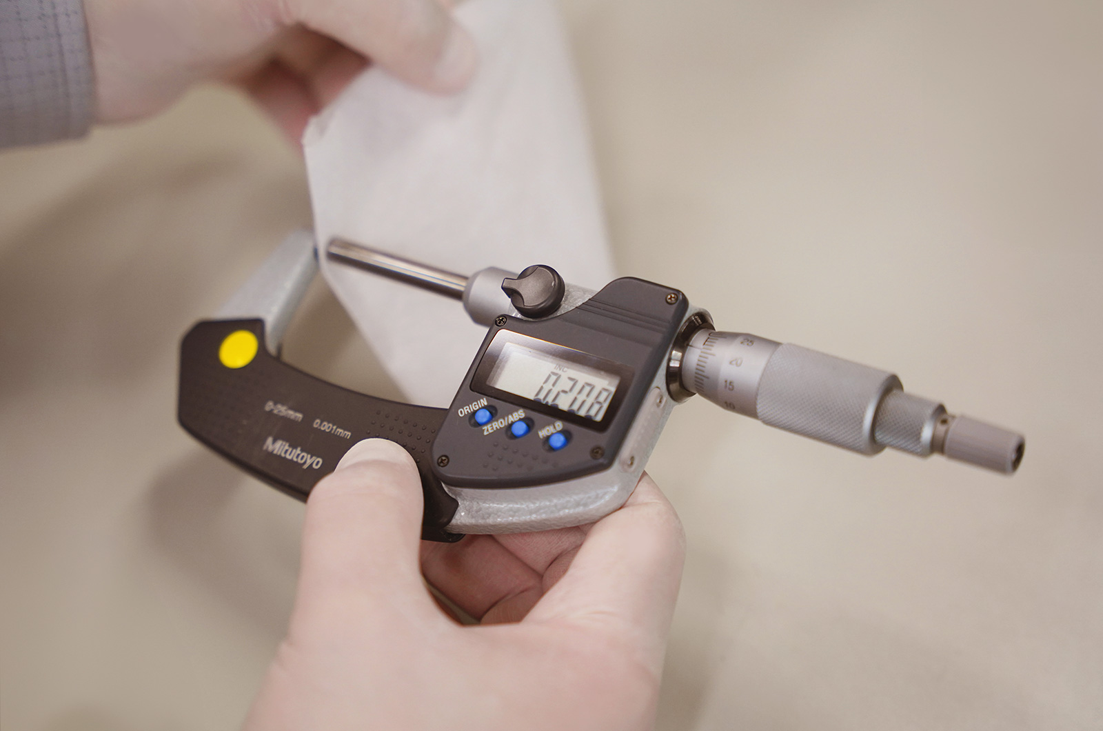
2) Clean the measuring surfaces
Clean the measuring surfaces of the anvil and the spindle tip. Place a clean, dry piece of paper or cloth between the two surfaces and gently pull it out to remove dust and fine debris.
3) Check the zero point (zero setting)
Before measurement, always check the zero point of the micrometer. Slowly close the anvil and spindle using the ratchet stop until the measuring surfaces lightly contact each other. The clicking sensation as the ratchet begins to slip indicates that the correct measuring force has been applied.
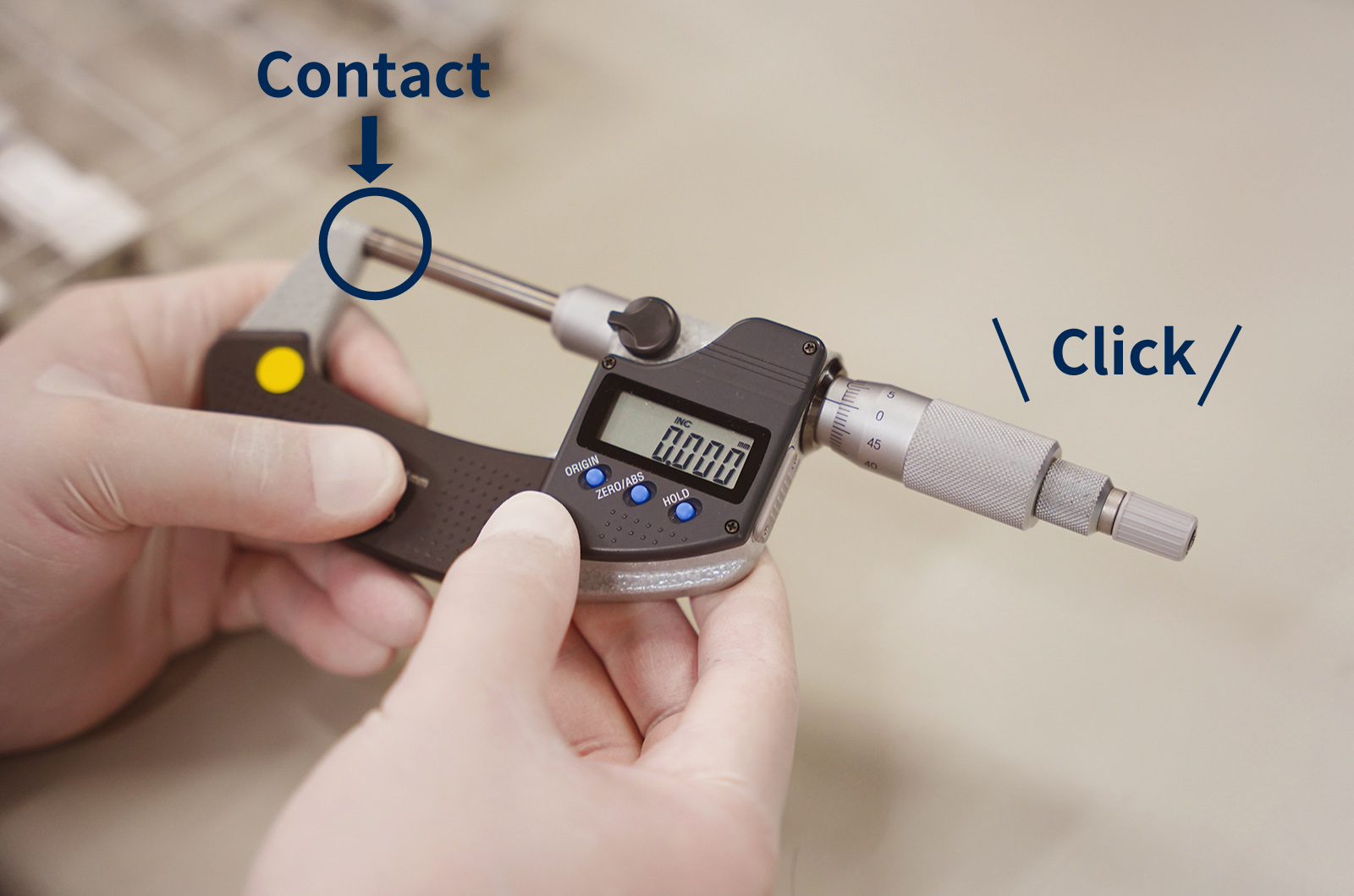
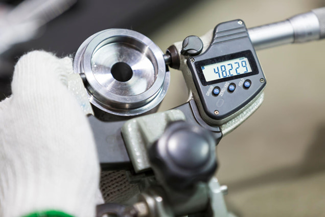
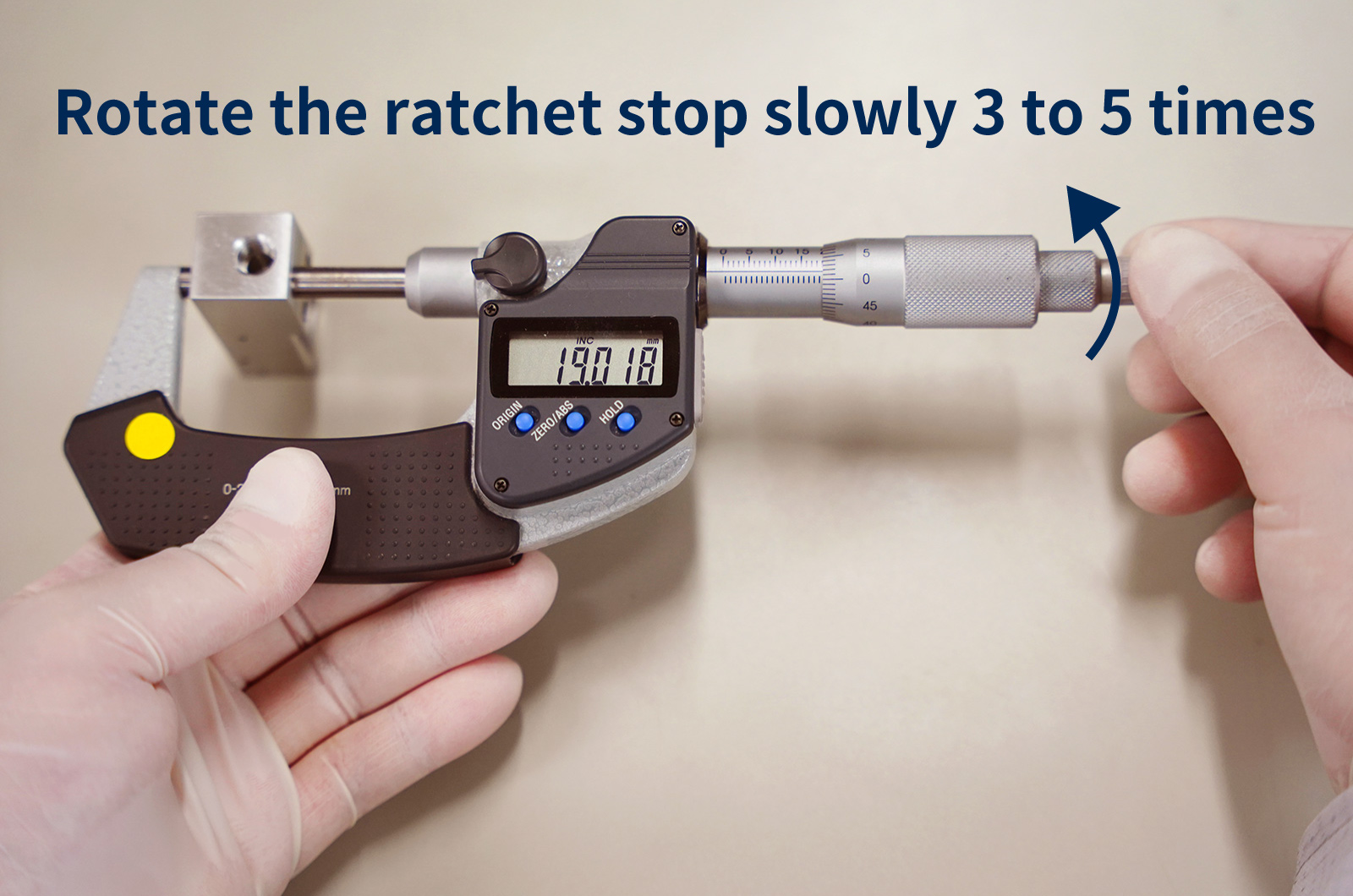
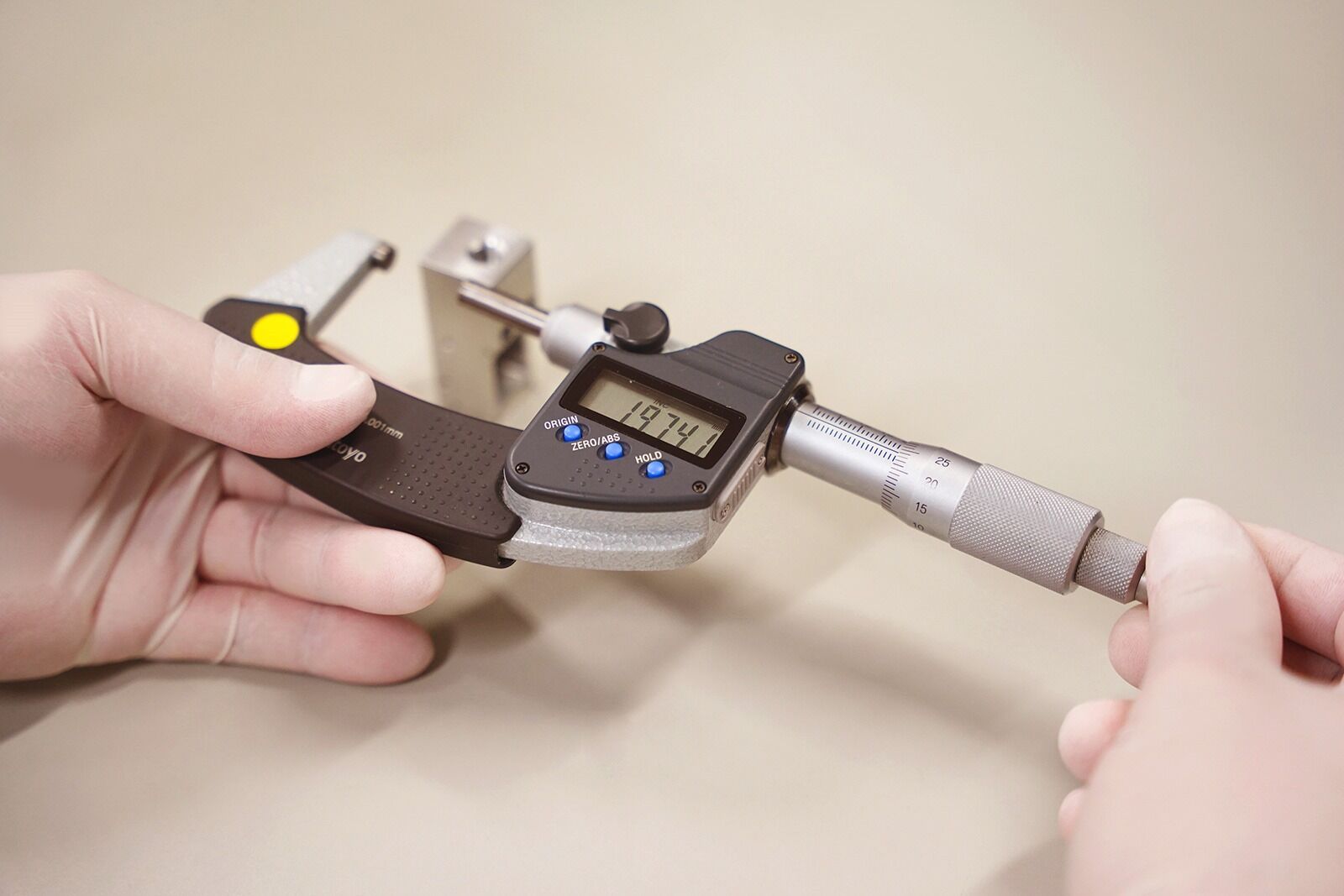
4) Perform the measurement
Now proceed with measuring the workpiece. Place the workpiece straight between the anvil and the spindle, and slowly close the micrometer by turning the thimble. Once the measuring surfaces make contact, rotate the ratchet stop slowly 3 to 5 times using the same posture and force as during zero-point checking to apply the proper measuring force.
5) Read the scale
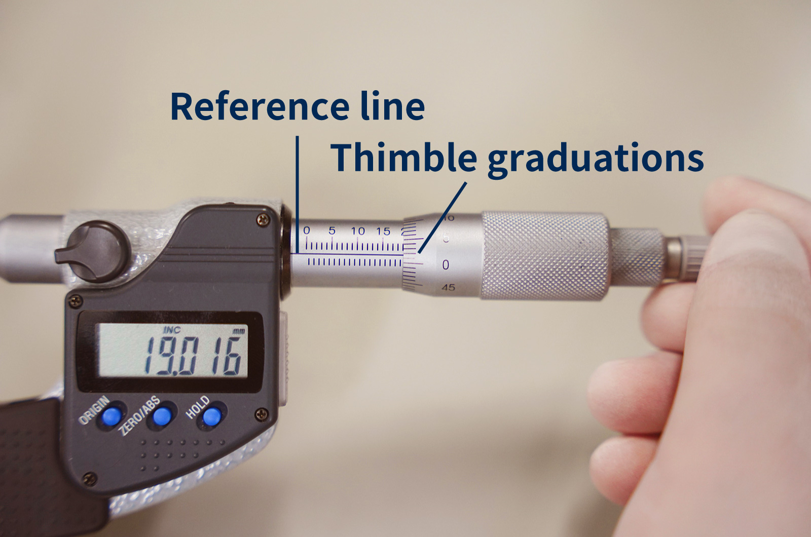
Carefully read the graduations on the sleeve and the thimble (for digital micrometers, simply read the displayed value).
For analog micrometers, first check the sleeve scale and read the last fully visible value. For example, if the sleeve shows up to 19 mm, the reading at this stage is 19 mm. Next, read the thimble graduation that aligns with the reference line on the sleeve. If the aligned mark is “1,” this corresponds to 0.01 mm. Add these values together to obtain the measurement result (for example, 19 + 0.01 = 19.01 mm).
If no thimble graduation exactly aligns with the reference line, read the graduation just below the reference line and add it to the sleeve value to determine the final measurement.
6) After measurement
After completing the measurement, slightly open the spindle and remove the workpiece. If multiple locations need to be measured, repeat the above procedure for each measurement point.
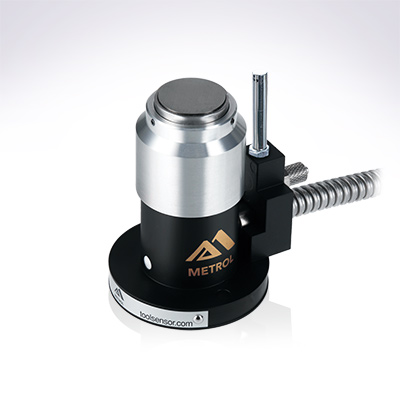
What Are Metrol’s High-Precision Positioning Sensors?
A micrometer has a seemingly simple structure, but it is composed of several components that enable precise measurement. Below, we explain the main components in particular.
High-Precision Positioning Touch Switches
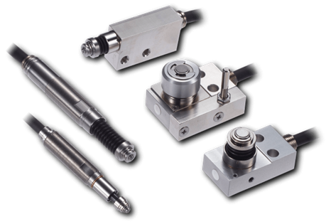
These are contact-type high-precision switches used for positioning and workpiece presence detection in machine tools, robots, and jigs. They achieve an extremely high repeatability of up to 0.5 µm and feature IP67-rated waterproof and dustproof protection, ensuring stable operation even in harsh environments. With more than 200 standard models available, they offer a wide range of variations, including designs for confined spaces, high-temperature environments, vacuum applications, and low contact force requirements.
Tool Setter (Tool Length Measurement Sensor)
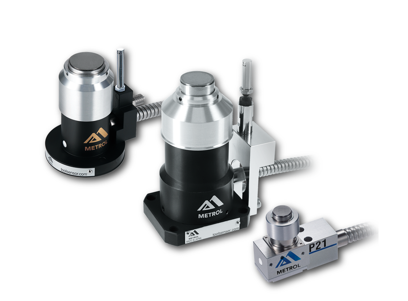
This is a contact-type sensor installed on CNC machine tools and industrial robots for tool length measurement, reference position setting, and tool breakage detection. By automatically measuring and compensating for tool length, wear, and thermal displacement inside the machine, it helps prevent machining defects and significantly reduces setup time. It is one of Metrol’s best-selling products, with a proven track record of more than 500,000 units shipped in 74 countries worldwide.
Touch Probe (On-Machine Measurement Probe)
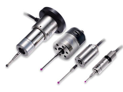
This is a contact-type probe for in-machine measurement, installed on machine tools and robots to automatically perform workpiece positioning (centering) before machining and dimensional measurement after machining. With a repeatability of 1 µm, it automates workpiece referencing and dimensional inspection, replacing skilled manual operations to reduce setup time and help prevent machining defects. Both wired and wireless models are available, meeting retrofit needs for 5-axis machining centers and robotic applications.
Air Gap Sensor (Pneumatic Sensor)
This is a non-contact sensor that uses air pressure to detect workpiece seating conditions with micron-level accuracy. It can detect gaps (“lift”) of less than 10 µm—previously difficult to measure—with a repeatability of ±0.5 µm, helping prevent machining defects and equipment downtime caused by insufficient contact between the workpiece and fixture. The sensor is used in applications such as semiconductor manufacturing processes, precision part clamping operations, and grinding wheel positioning on grinding machines, and it is a smart sensor that also supports the international standard IO-Link communication.