What Is Machining? From Definitions and Classification to Tools and Cutting Conditions
Machining is a representative manufacturing method in which materials such as metals and resins are removed by cutting to create the desired shape.
This article clearly explains the definition of machining, its position within the broader field of manufacturing, the types of machine tools used, their advantages and disadvantages, and key machining parameters (cutting conditions).
Table of Contents
What Is Machining?
Machining is a process in which a cutting tool removes part of a material to form a desired shape.
It generally refers to cutting metals using machines such as lathes and milling machines, but it is also applied to wood and plastics. Machining is classified as a material removal process, characterized by shaping through the removal of material.
This principle differs from plastic forming processes such as forging and pressing, which create shapes by deforming materials with large forces.
Position of Machining Within Manufacturing Processes
Manufacturing processes can be classified into several categories based on their underlying principles.
Broadly, they include material removal processes that shape materials by cutting, forming processes that deform materials using force or heat, and joining processes that connect multiple components.
| machining category | Examples of major processes | Overview |
|---|---|---|
| Material removal processes (machining by removing material) | Cutting (turning/lathe machining, milling, drilling), grinding/polishing (using grinders and grinding wheels), electrical discharge machining (EDM), etc. | A method of creating shapes by removing material with tools or grinding wheels. Enables part machining with high dimensional accuracy. Cutting is a representative example of material removal processes. |
| Forming processes (machining by plastic deformation and casting) | Forging, press forming, sheet metal bending, casting, injection molding, etc. | A method that applies large force or heat to deform material and form shapes that follow a die or mold. Since material is not removed, material yield is high. Many processes use dies or molds. |
| Joining processes (bonding materials together) | Welding, brazing, adhesive bonding, riveting, etc. | A method of joining multiple parts or materials to integrate them into one. By connecting components, complex products can be assembled. |

As shown above, machining is classified as a material removal process. While material removal also includes grinding, polishing, and special processes, machining is the most fundamental and central method within this category.
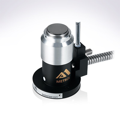
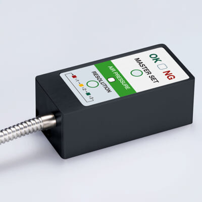
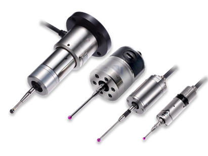
Automates originating of cutting tools
- Tool Setter -
Tool length and chips are monitored to prevent machining defects due to wear and thermal displacement
Click here ›Main Machine Tools Used for Machining
Machining is performed using specialized equipment known as machine tools.
Three representative machine tools for cutting are lathes, milling machines, and machining centers.
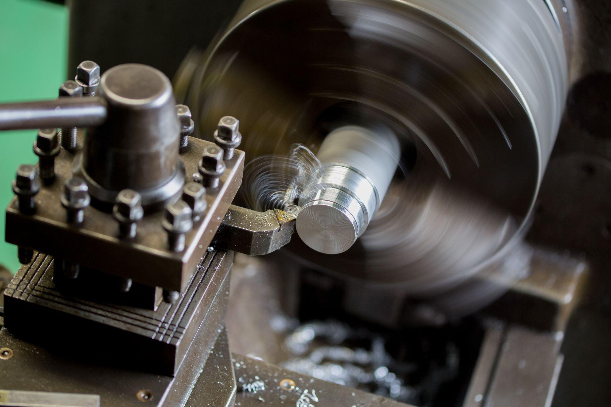
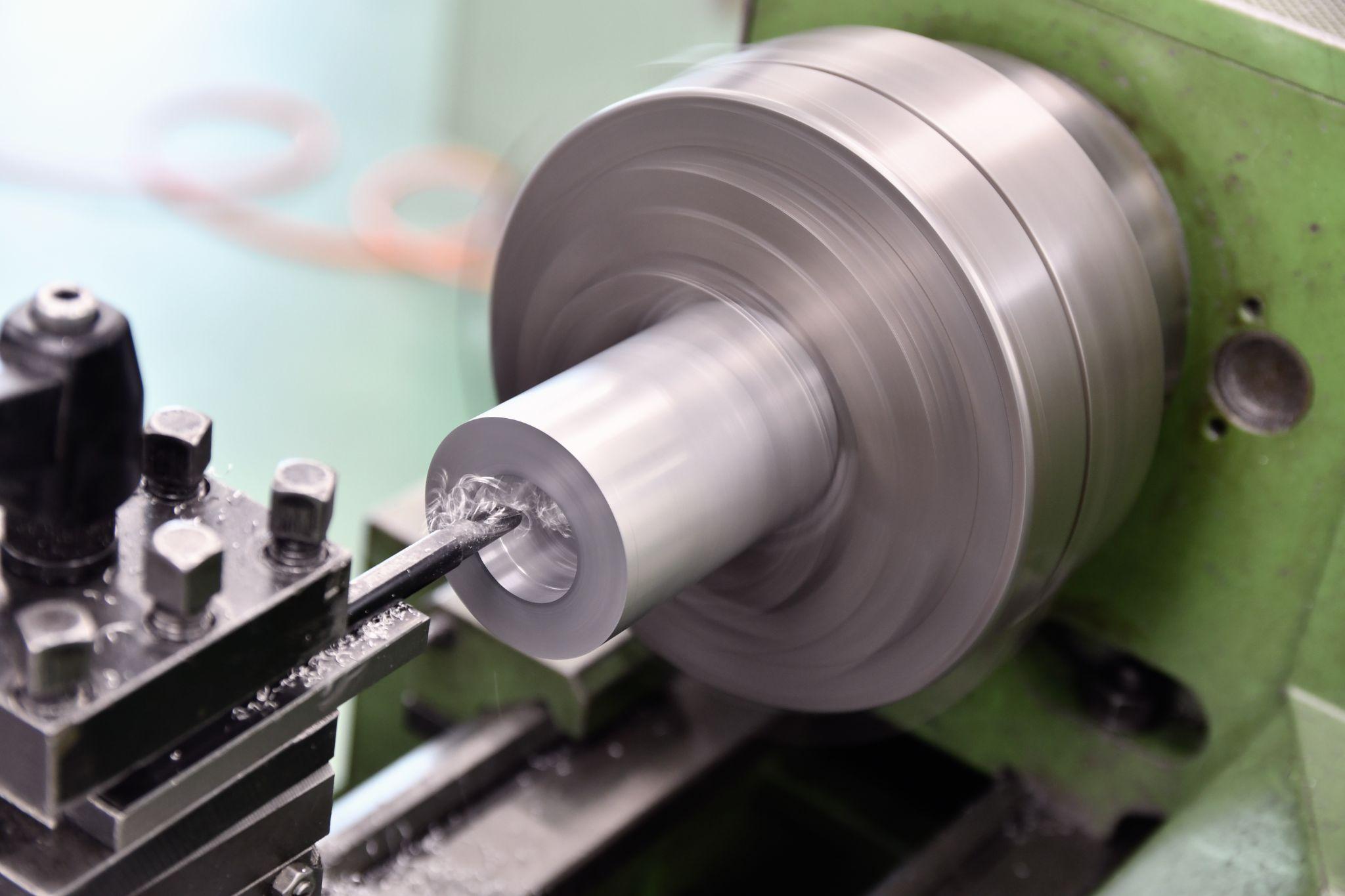
Lathe
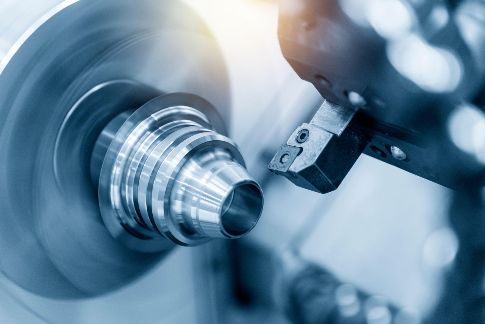
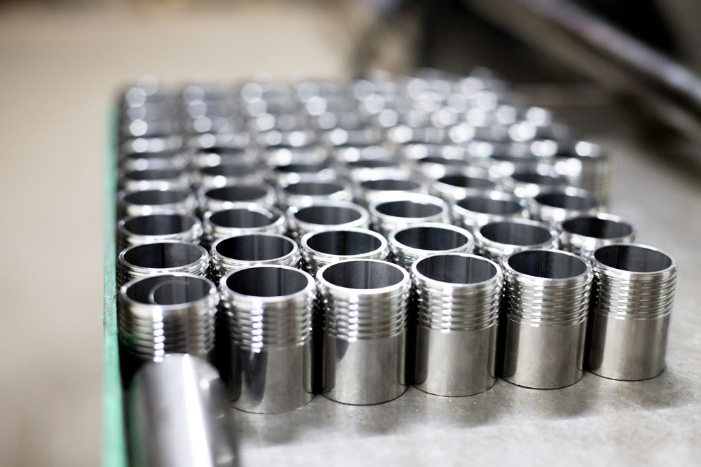
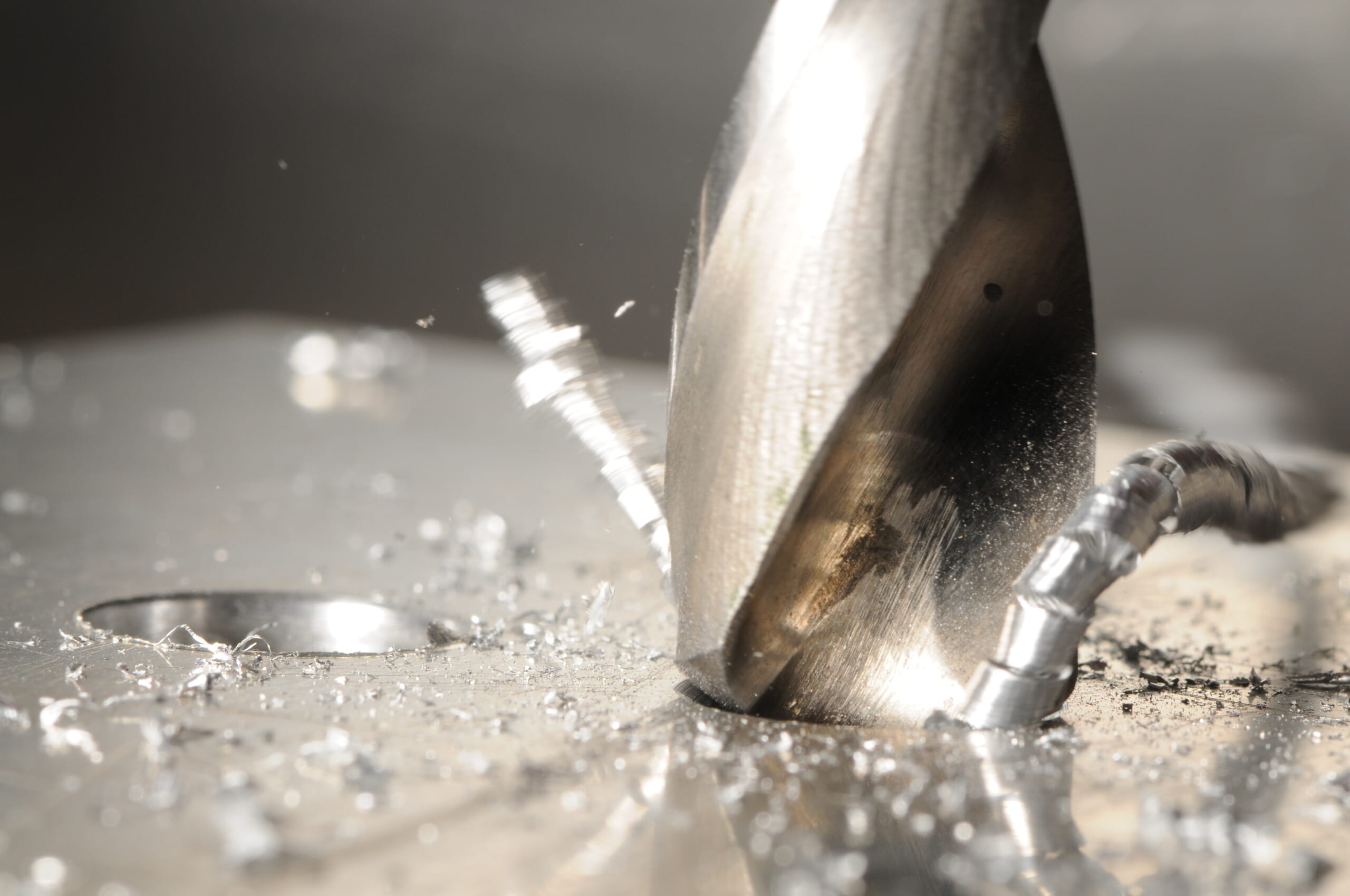
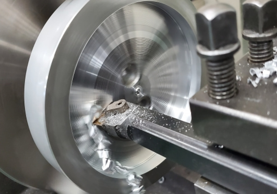
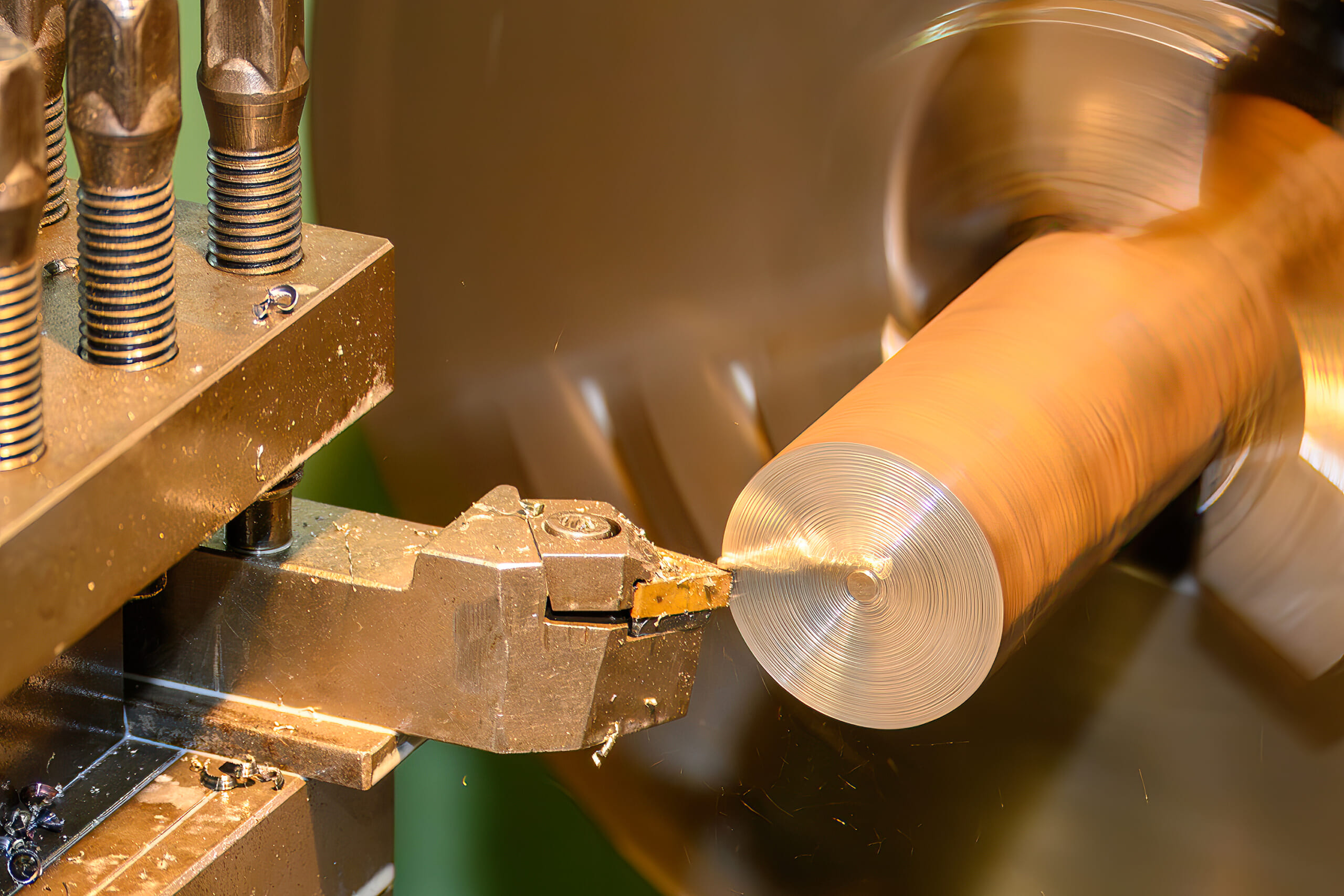
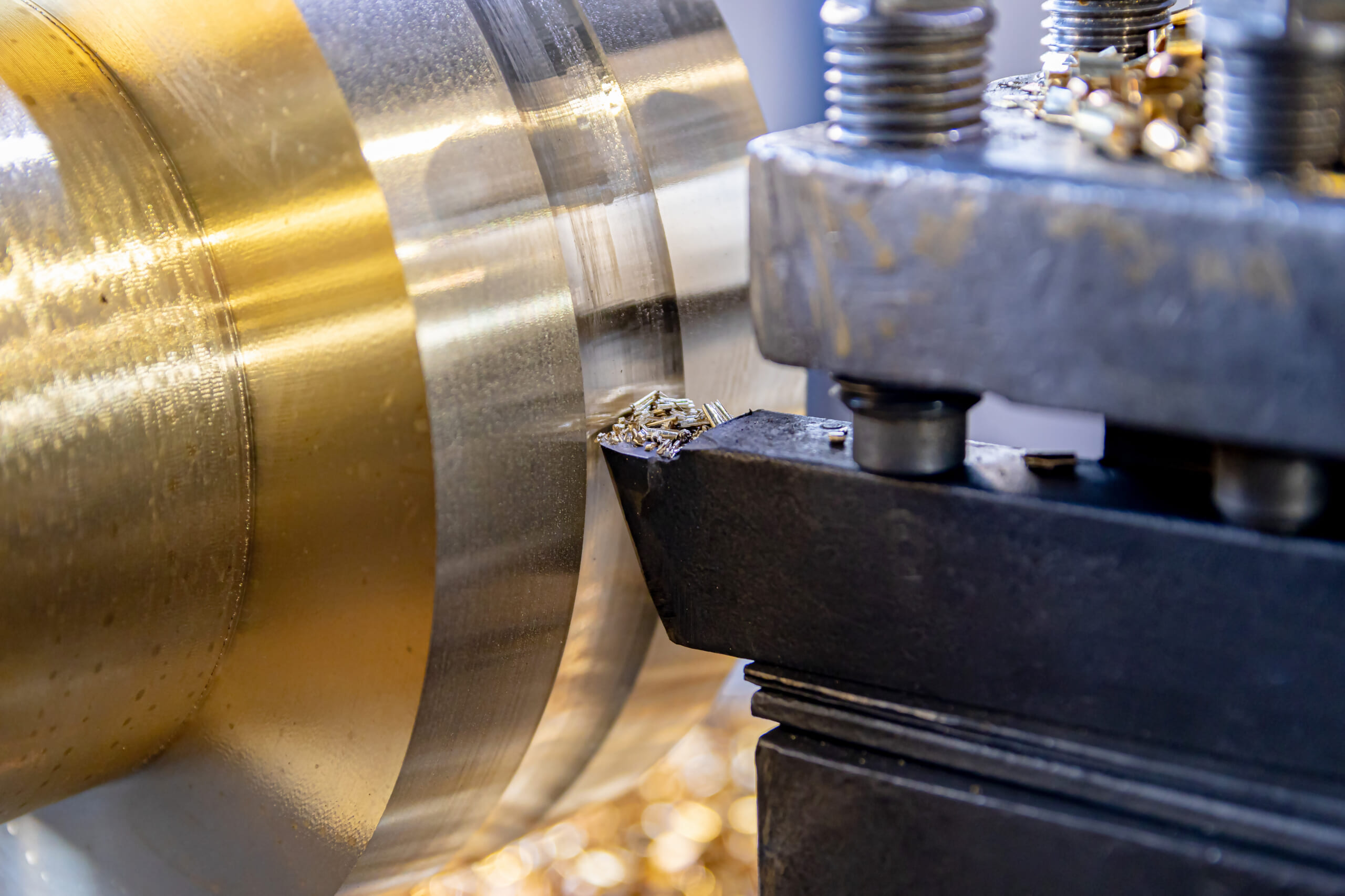
A lathe is a machine tool that machines a workpiece by rotating it at high speed while a fixed cutting tool (lathe tool) is applied to remove material.
The workpiece rotates while the tool is fed primarily in a linear direction. Because machining on a lathe produces shapes that are symmetrical around the axis of rotation, it is well suited for cylindrical and disk-shaped components.
Lathes support a wide range of operations, including outer diameter turning of shafts and cylindrical parts, boring to enlarge internal holes, facing, threading, grooving, and parting-off.
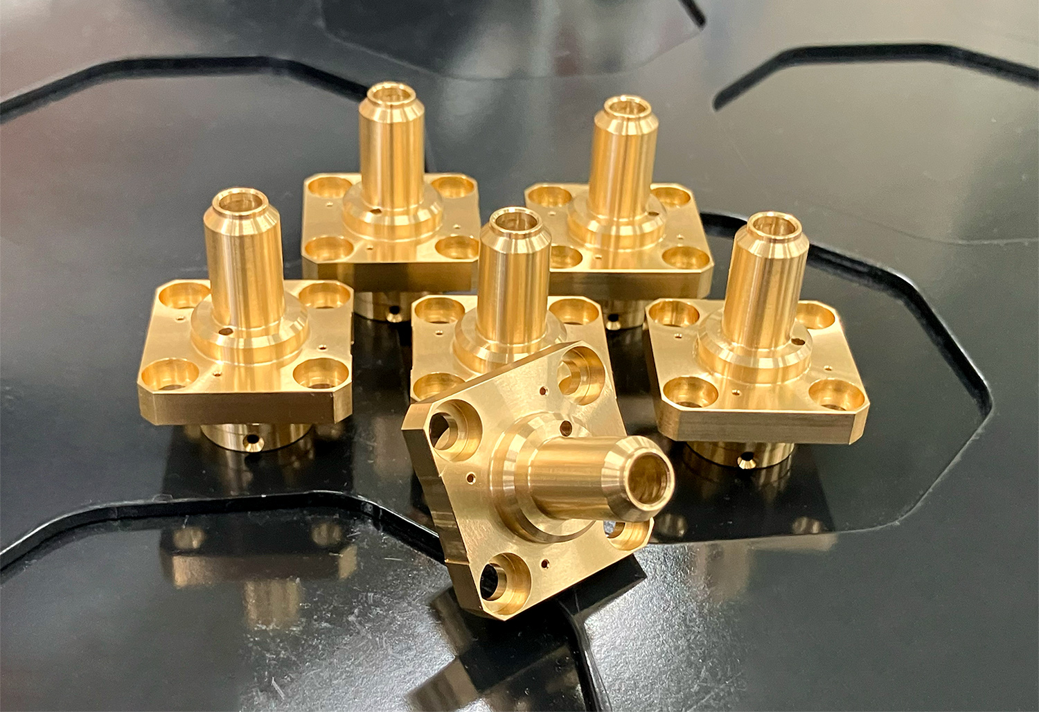
Milling Machine
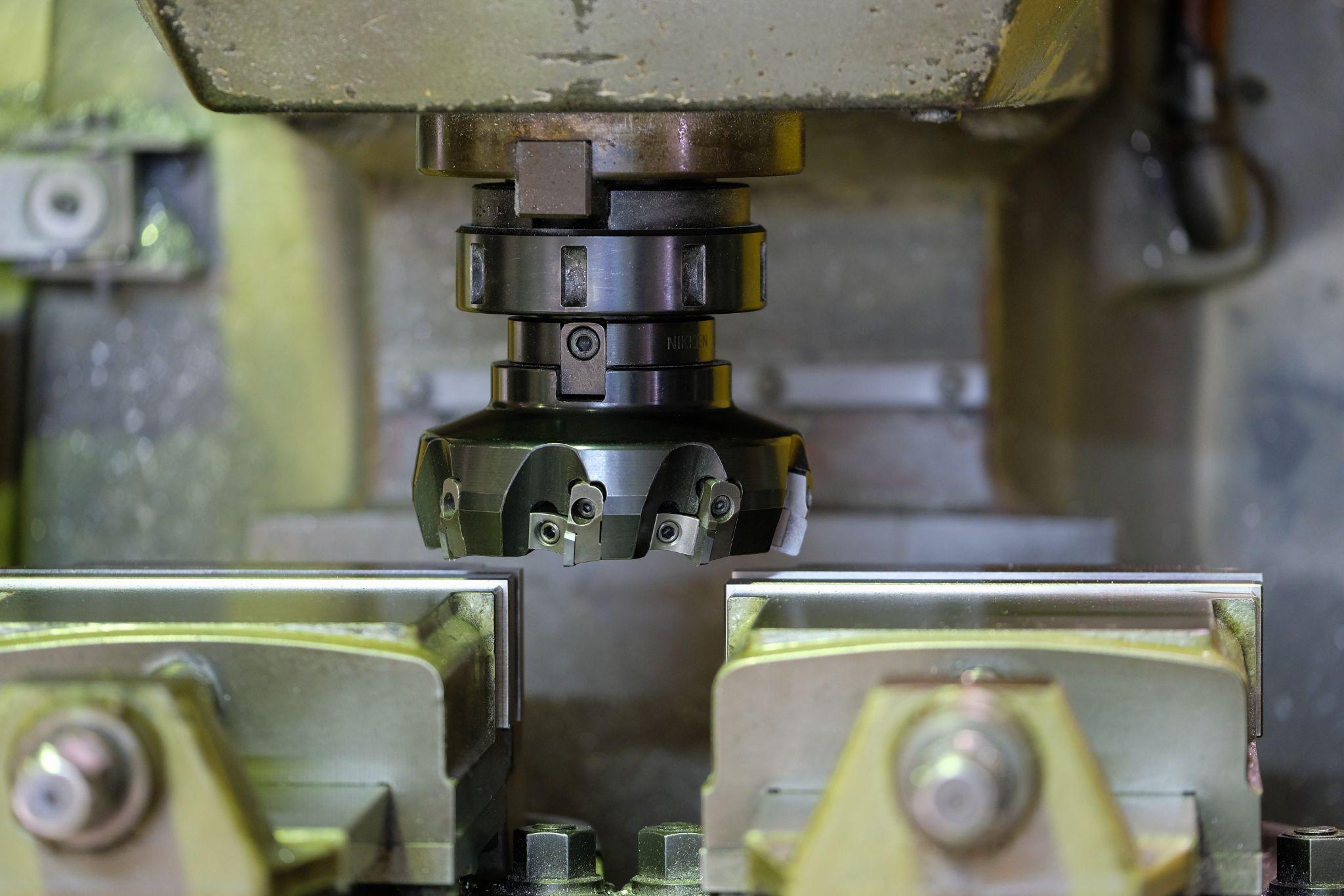
A milling machine is a machine tool that removes material by pressing a rotating cutting tool—such as a milling cutter or end mill—against a workpiece.
Unlike a lathe, the tool rotates while the workpiece is fixed on the machine table during machining.
By rotating the tool while removing material, milling machines are suitable for machining flat surfaces, grooves, and holes. They are particularly effective for face milling, side milling, slotting, and step machining of block-shaped workpieces.
Milling machines mount multi-edge cutting tools such as end mills or cutters on the spindle. The tool rotates at high speed and machines the workpiece, which is secured to the table with a vise or fixture, along a programmed tool path.
Machining Center
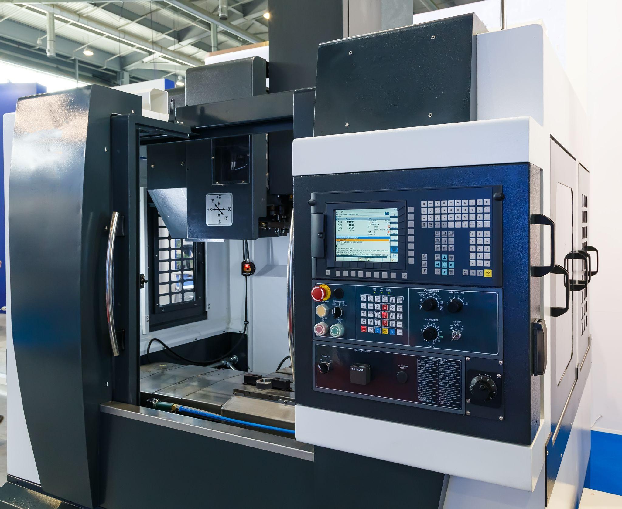
A machining center is a numerically controlled (NC) machine tool equipped with an automatic tool changer, enabling multiple machining operations to be performed continuously.
Essentially an advanced form of an NC milling machine, a machining center houses numerous end mills and drills in a tool magazine and automatically changes tools according to the program, performing milling, drilling, boring, and tapping operations in a single setup.
It is a highly automated machine tool developed to achieve both high machining accuracy and high productivity.
In a machining center, the workpiece is mounted on a fixed or movable table, while the tool attached to the spindle rotates at high speed to perform machining.
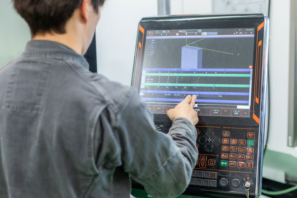
The NC controller precisely controls the X, Y, and Z axes, and depending on the configuration, multi-axis control (3-axis to 5-axis) that rotates or tilts the table or spindle is also possible.
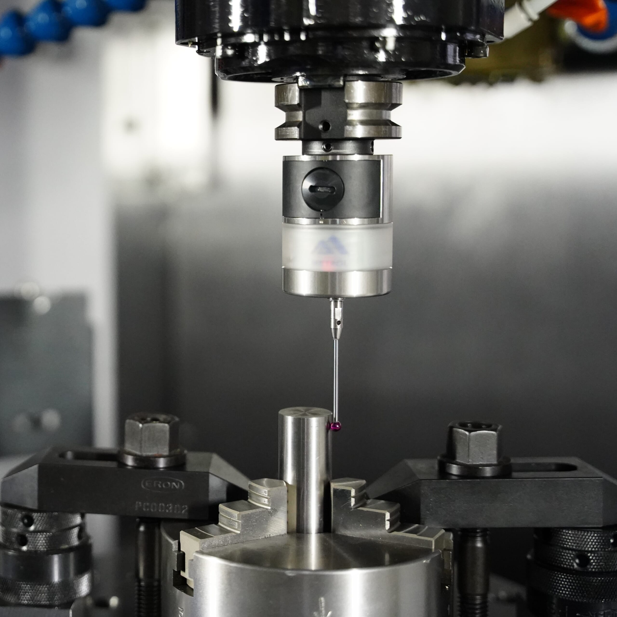
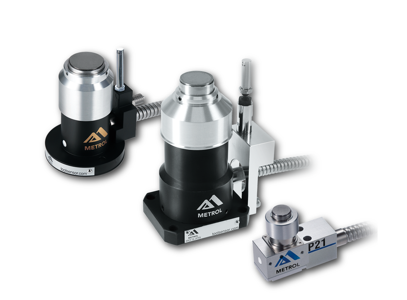
Automated workpiece centering and positioning
- Touch probe -
A contact/touch sensor for on-machine measurement that improves the efficiency of setup work
Click here ›Advantages and Disadvantages of Machining
Below are the main advantages and disadvantages of machining, a process that forms desired shapes by pressing cutting tools against a material while generating chips.
Advantage 1: High-Precision Machining at Low Cost
Machining removes material from solid stock to create arbitrary shapes, enabling high-precision manufacturing at relatively low cost.
Because machining does not require molds or dies like casting or forging, it allows for shorter lead times and lower costs, making it ideal for prototyping and low-volume, high-mix production.
High-precision machining that is difficult to achieve with casting or forging can be readily accomplished through machining.
Advantage 2: High Degree of Freedom in Machined Shapes
As long as the shape falls within the motion range of the machine tool, machining offers a high degree of freedom in achievable geometries.
In processes such as pressing or sheet metal forming, machinable material thickness is limited by machine capacity; machining does not face this constraint.
With machine tools such as machining centers and CNC lathes, shapes that were once difficult to produce manually can now be machined accurately.
Advantage 3: Compatibility with a Wide Variety of Materials
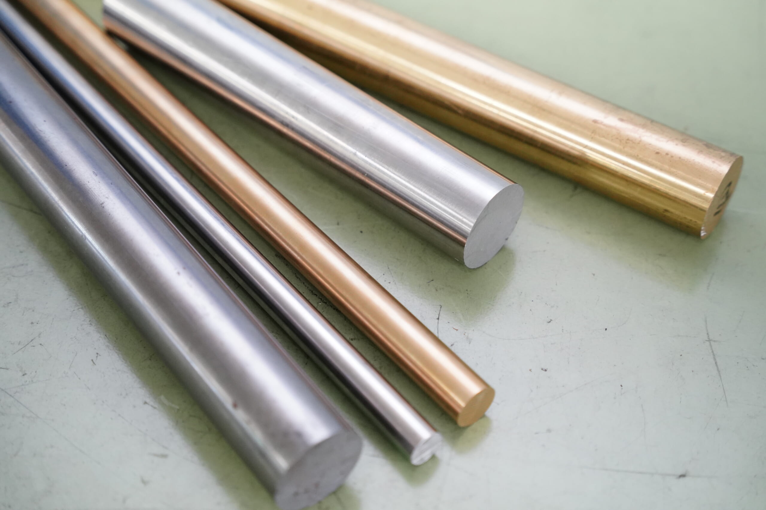
One of the strengths of machining is its ability to process a wide range of materials, including ferrous metals, aluminum, copper, and resins.
With appropriate tool materials and geometries, machining can also be applied to wood and even stone.
If a material can be cut with a tool, machining can generally be applied-this versatility is a major advantage.
Disadvantage 1: Skilled Operators Are Required
While machining offers great freedom in shape, producing high-precision components requires skilled operators and a high level of expertise.
Although numerical control systems now enable less-experienced operators to machine complex shapes, high-precision machining still relies heavily on skilled craftsmanship.
Selecting appropriate tools and mastering machining methods suited to specific materials and geometries cannot be achieved overnight.
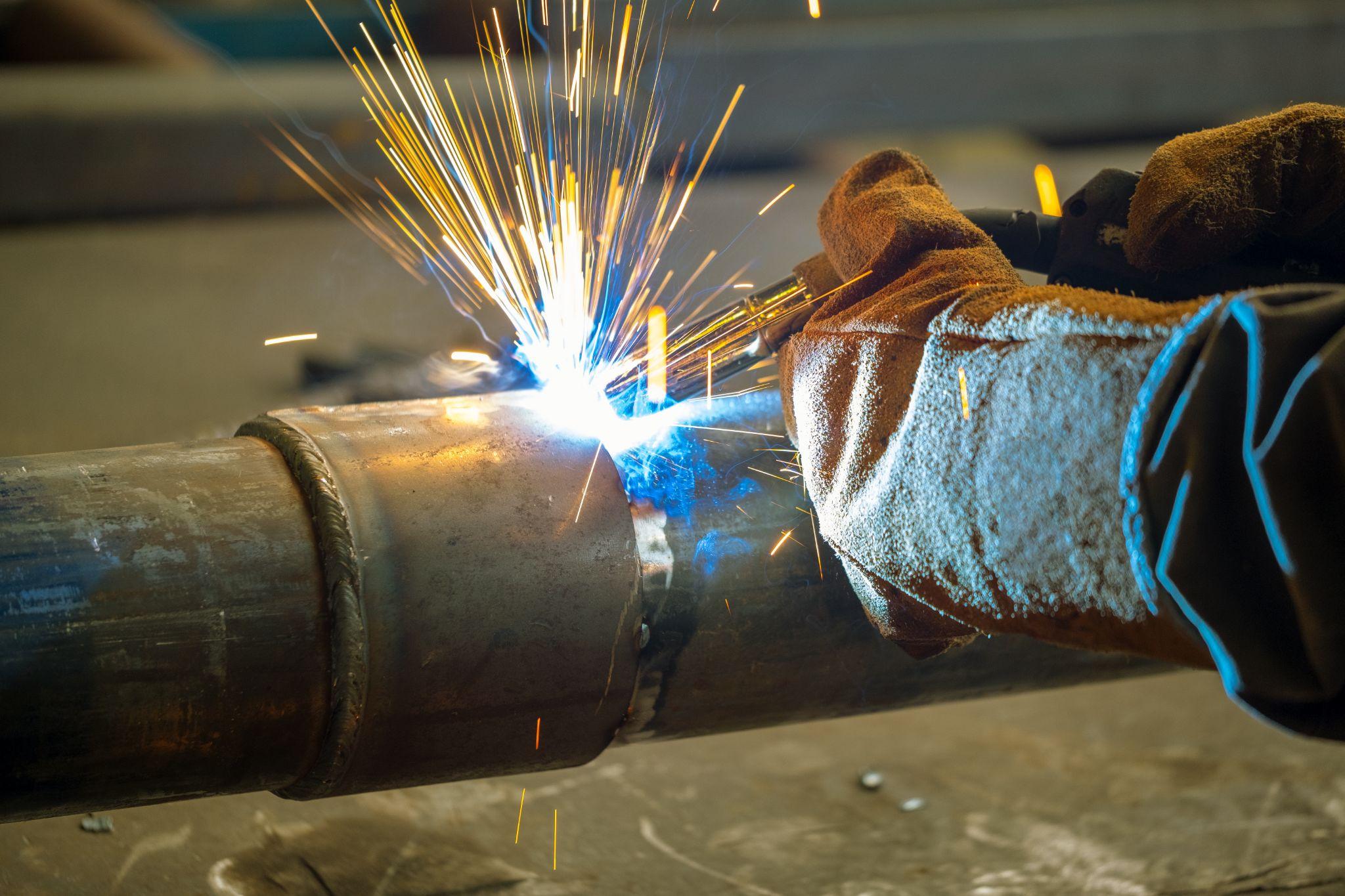
Disadvantage 2: Chip-Related Issues Cannot Be Eliminated
Because machining removes unnecessary material to create a desired shape, chip-related issues cannot be completely eliminated.
Chips are generally harder than the original material, and when they adhere to the cutting edge, they can cause tool damage or accelerate wear.
Chip clogging, built-up edge, surface scratches, tool breakage, and even machine accidents or failures can all be caused by chips.
Proper application of cutting fluids and the use of air blow systems help minimize chip-related problems.
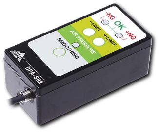
High-precision seating confirmation of workpiece and jig
- Air Gap Sensor -
You can check not only "presence/absence" but also "adhesion (gap)" at the same time with a repeatability of ±0.5 μm.
Click here ›Disadvantage 3: Costs May Increase Depending on Material and Geometry
Depending on the workpiece material and geometry, machining costs can become high, which is one of its drawbacks.
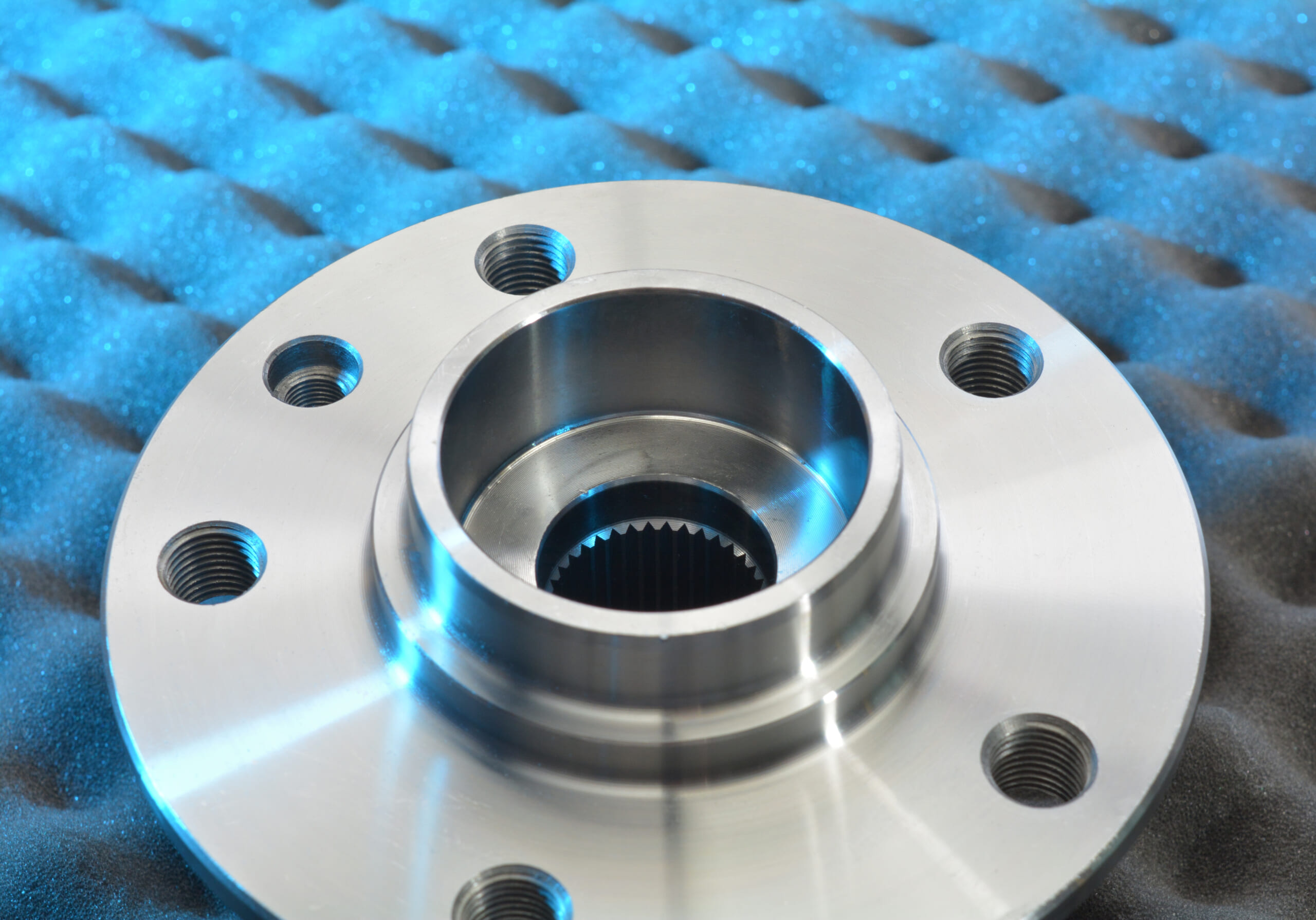
For example, shafts with large flange diameters relative to the shaft diameter require a large volume of material removal, increasing machining time and tool consumption (such as indexable inserts), which results in higher costs.
Machining components used in harsh environments or high-hardness materials also increases costs due to higher material prices and expensive cutting tools.
Machining Parameters (Cutting Conditions)
When performing machining, various cutting conditions must be set for the machine tool and cutting tools.
Machining parameters define how machining is performed and include values such as cutting speed, feed rate, and depth of cut, as well as tool material and coating, and coolant usage.
Below, we explain the key cutting conditions and provide an overview of each.
Cutting Speed (Surface Speed)
Cutting speed represents the speed at which the tool cuts the material and is defined as the relative surface speed at the workpiece surface, typically expressed in m/min.
On a lathe, it refers to the speed at which the rotating workpiece is cut by the tool, while on a milling machine it corresponds to the peripheral speed of the end mill contacting the material.
The appropriate cutting speed depends on both the tool material and the workpiece material.
In general, harder tools with higher heat resistance allow for higher cutting speeds.Excessively high cutting speeds cause high tool temperatures, leading to wear or burning, while speeds that are too low increase machining time and reduce efficiency.
Setting an appropriate cutting speed ensures tool life while reducing machining time.
Feed Rate
Feed rate refers to the speed at which the tool or workpiece moves and is expressed as the distance traveled per minute (mm/min).
On a lathe, feed rate indicates how fast the cutting tool moves longitudinally or radially, while on a milling machine it refers to how fast the table or tool advances.
Higher feed rates increase material removal per pass and improve productivity, but they also raise cutting forces, which can worsen surface finish and increase loads on the tool and machine.
Conversely, lower feed rates produce smoother and more precise surfaces, but at the cost of longer machining time.
By selecting an appropriate feed rate, it is possible to maintain the desired surface finish while minimizing machining time.
Depth of Cut
Depth of cut refers to how deeply the cutting tool penetrates into the workpiece, representing the thickness of material removed.
For example, in outer diameter turning on a lathe it is the radial amount removed, while in face milling it is the depth to which the cutter engages the material.
A larger depth of cut increases material removal per pass and shortens machining time, but it also raises cutting resistance and tends to reduce accuracy. A smaller depth of cut reduces cutting load and improves accuracy, but requires multiple passes, increasing total machining time.
Excessive depth of cut can cause deflection of the workpiece or tool, leading to chatter, while an extremely small depth may prevent the tool from properly engaging the material.
Therefore, it is important to set an appropriate depth of cut within a stable range, taking into account workpiece and machine rigidity.
Tool Material
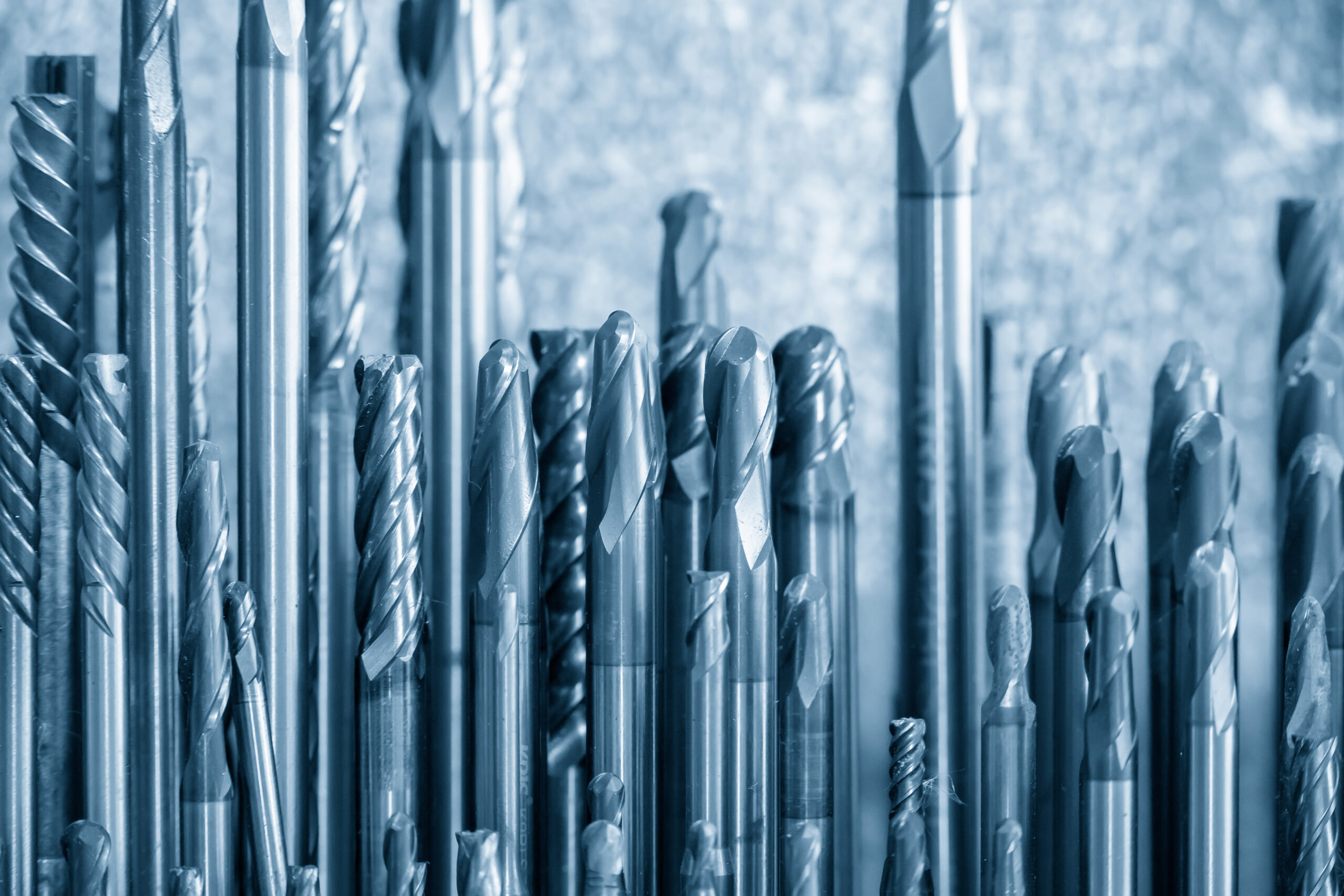
Tool material is also a critical factor in machining conditions.
Common tool materials include high-speed steel (HSS), cemented carbide, cermet, ceramics, CBN (cubic boron nitride), and diamond (PCD).
Each material differs in hardness, toughness, and heat resistance, resulting in different optimal machining conditions.
HSS offers excellent toughness and ease of machining, but its lower hardness and heat resistance require relatively low cutting speeds.
Cemented carbide provides a good balance of hardness and toughness and maintains strength at high temperatures, enabling higher-speed and higher-efficiency machining than HSS. It is widely used as a standard tool material.
Ceramic and CBN tools offer even higher hardness and heat resistance, making them suitable for machining hardened steels and ultra-high-speed cutting. However, their low toughness makes them sensitive to impact, so they are used under stable conditions with small depths of cut and feed rates.
Diamond tools (PCD) are the hardest and most wear-resistant, but they are susceptible to chemical reactions with ferrous materials. They are mainly used for high-speed machining of non-ferrous materials such as aluminum alloys, copper, resins, and CFRP.
Cooling and Lubrication Method
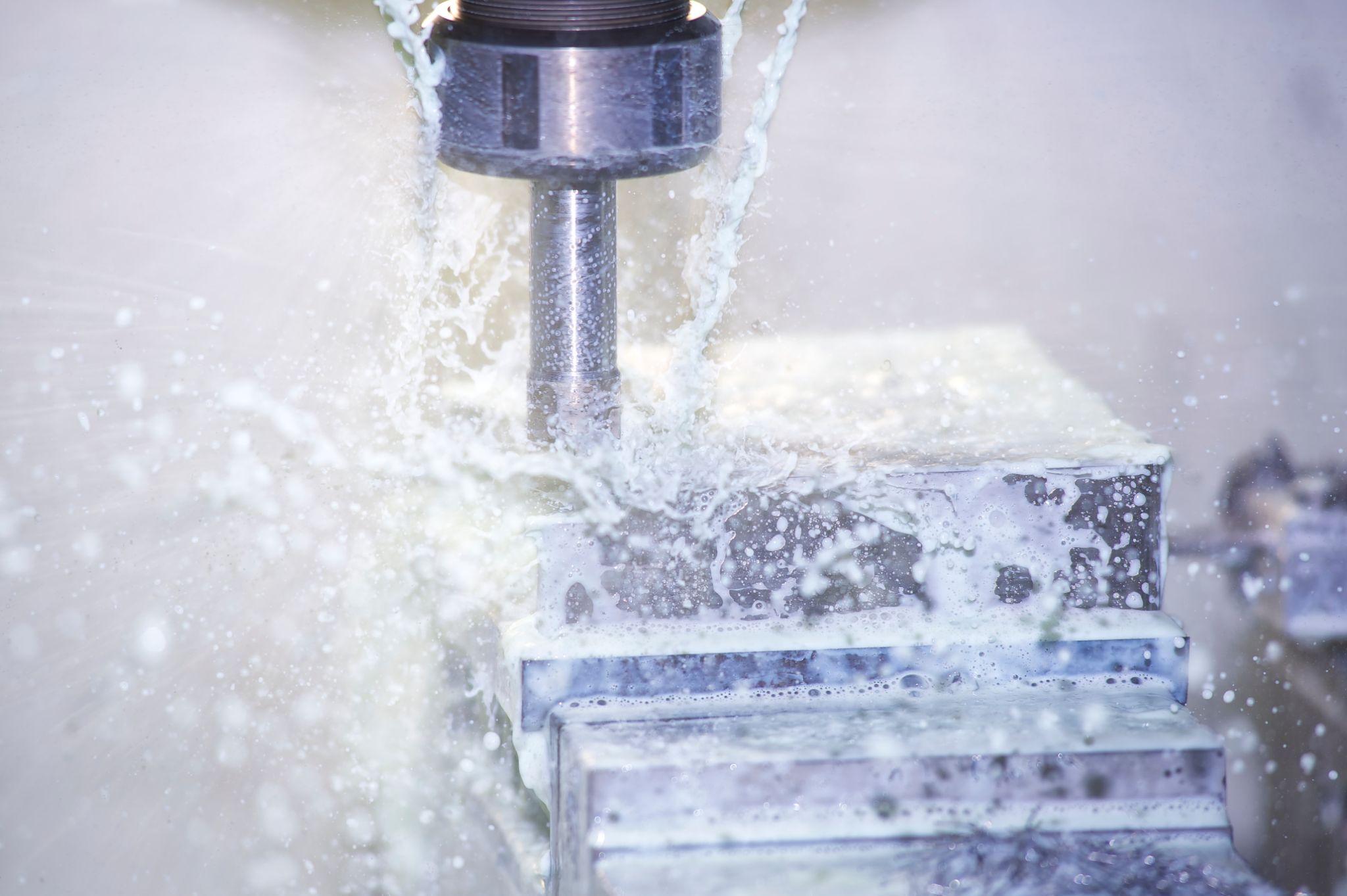
In machining, cutting fluids (coolants) and cutting oils are commonly used to cool and lubricate the cutting area.
During cutting, friction between the tool and workpiece generates significant heat, which can cause tool wear and dimensional inaccuracies. Spraying coolant cools the cutting edge and suppresses thermal effects.
Lubrication also reduces frictional resistance and helps chips to be discharged smoothly.
What Are Metrol’s High-Precision Positioning Sensors?
In machining environments, accurate positioning of components is critical for precisely machining fine features and complex contours.
As manufacturing processes become more efficient and automated, even slight positional deviations can significantly affect final product quality, increasing the need for precise positioning.
This is where Metrol’s advanced positioning sensors play a crucial role.
High-Precision Positioning Touch Switches
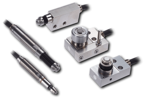
These are contact-type high-precision switches used for positioning and workpiece presence detection in machine tools, robots, and jigs. They achieve an extremely high repeatability of up to 0.5 µm and feature IP67-rated waterproof and dustproof protection, ensuring stable operation even in harsh environments. With more than 200 standard models available, they offer a wide range of variations, including designs for confined spaces, high-temperature environments, vacuum applications, and low contact force requirements.
Tool Setter (Tool Length Measurement Sensor)
This is a contact-type sensor installed on CNC machine tools and industrial robots for tool length measurement, reference position setting, and tool breakage detection. By automatically measuring and compensating for tool length, wear, and thermal displacement inside the machine, it helps prevent machining defects and significantly reduces setup time. It is one of Metrol’s best-selling products, with a proven track record of more than 500,000 units shipped in 74 countries worldwide.
Touch Probe (On-Machine Measurement Probe)
This is a contact-type probe for in-machine measurement, installed on machine tools and robots to automatically perform workpiece positioning (centering) before machining and dimensional measurement after machining. With a repeatability of 1 µm, it automates workpiece referencing and dimensional inspection, replacing skilled manual operations to reduce setup time and help prevent machining defects. Both wired and wireless models are available, meeting retrofit needs for 5-axis machining centers and robotic applications.
Air Gap Sensor (Pneumatic Sensor)
This is a non-contact sensor that uses air pressure to detect workpiece seating conditions with micron-level accuracy. It can detect gaps (“lift”) of less than 10 µm—previously difficult to measure—with a repeatability of ±0.5 µm, helping prevent machining defects and equipment downtime caused by insufficient contact between the workpiece and fixture. The sensor is used in applications such as semiconductor manufacturing processes, precision part clamping operations, and grinding wheel positioning on grinding machines, and it is a smart sensor that also supports the international standard IO-Link communication.