What Is a Ball Plunger? Applications, Selection Guide, and Design Tips
A ball plunger is a machine element that achieves positioning and temporary holding by letting a spring-loaded ball engage with a mating component. Although it is a small part, it is widely used in everything from manufacturing sites—such as machine-tool fixtures, adjustment mechanisms, and transfer lines—to everyday products.
This article organizes the basic structure and operating principle of ball plungers, material characteristics, and typical applications, then explains practical selection criteria, design considerations, and real-world use cases.
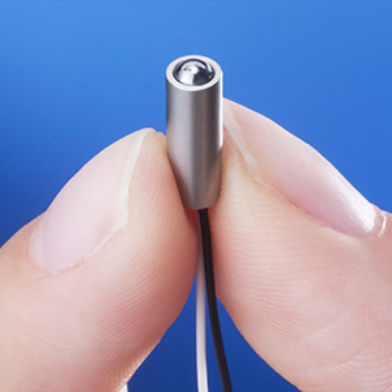
High Precision Positioning
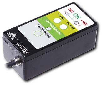
- Ball Plunger Switch Sensors -
Indexing by ball plunger and confirmation signal output. Reduce the number of parts to make smaller machines at lower costs.
Click here ›Table of Contents
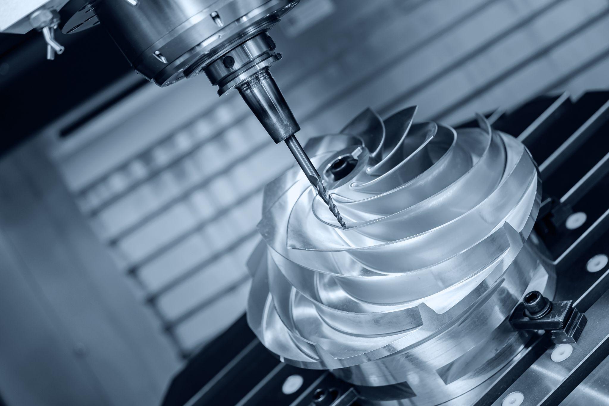
What Is a Ball Plunger? Basic Structure and Operating Principle
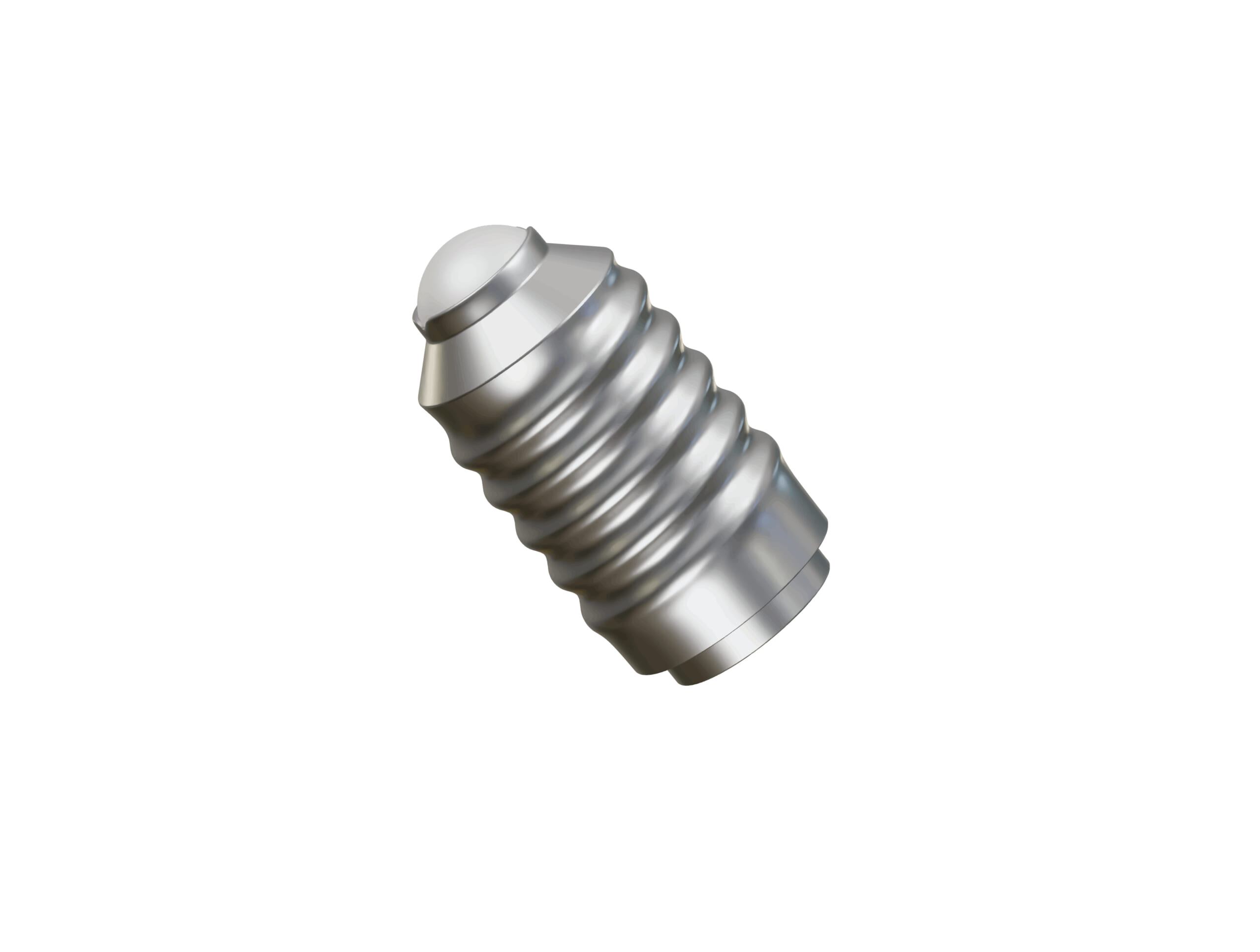
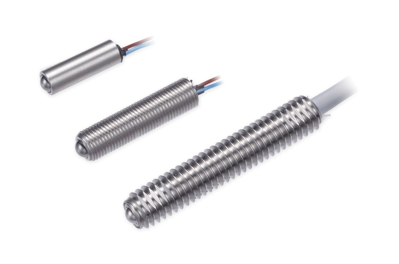
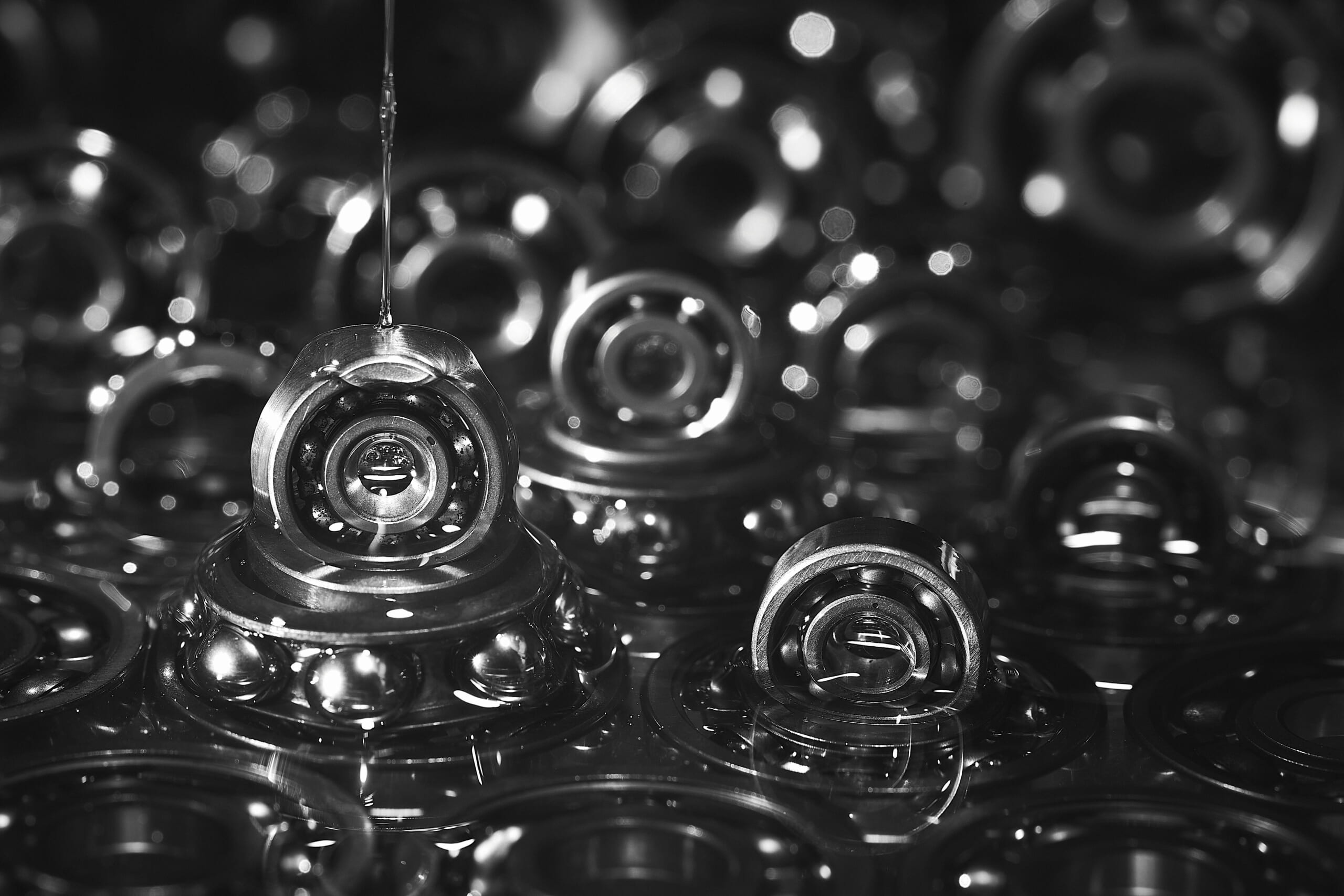
The body has a hollow structure containing a small compression spring, which continuously pushes the ball outward.
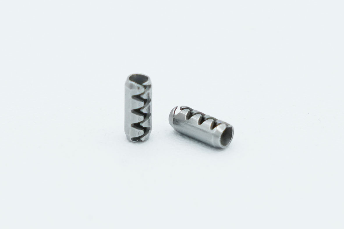
In common designs, the ball is exposed at one end of the outer sleeve (body), while the opposite end has male threads or grooves for mounting to equipment or fixtures.
When an external force is applied, the ball retracts into the body (compressing the spring), and when the force is removed, the ball is pushed out again.
This action allows the ball to seat into a mating recess or groove, locating the parts at a specified position and providing reliable retention (temporary holding) as needed.
When sufficient lateral force (side load) is applied, the ball is pushed back out of the recess (further compressing the spring), releasing the retention.
In short, the core role of a ball plunger is to provide a simple spring-loaded detent mechanism that enables repeatable positioning and easy engagement/disengagement.
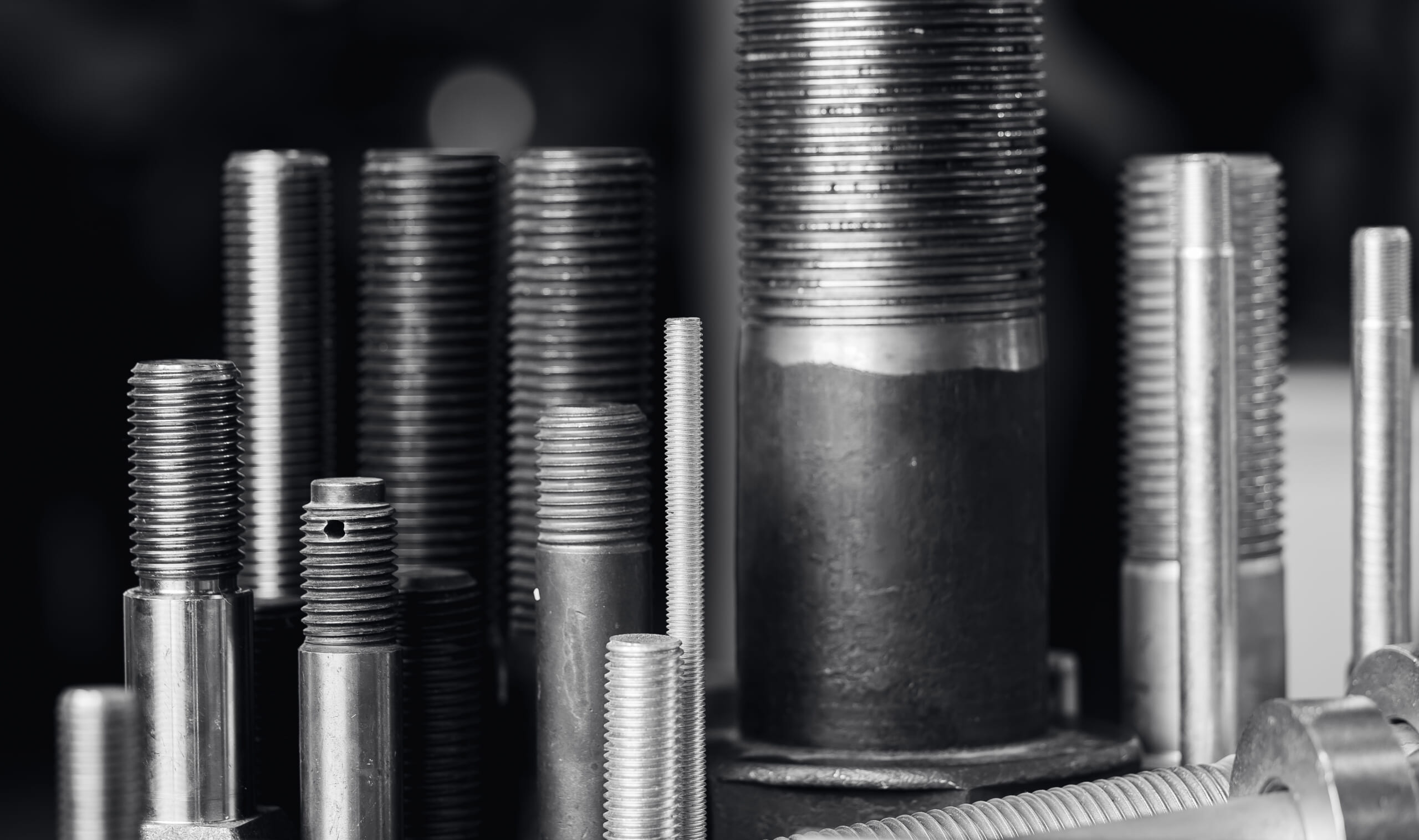
Main Materials and Their Characteristics
Ball plungers are manufactured using various material combinations depending on the application and environment.
Typical body (outer sleeve) materials include steel for high mechanical strength and machinability, stainless steel for corrosion resistance, and plastics. Steel bodies are often made of carbon steel and finished with black oxide or zinc plating to improve rust resistance.
Stainless-steel bodies resist rust even in humid or chemical environments and are suitable for clean applications such as medical equipment.
Plastic bodies (e.g., polyacetal/Delrin) are lightweight, non-magnetic, and corrosion-free, and they can reduce sliding noise and metal particle generation. However, plastics can deform under high temperature or heavy load, so they are often limited to light-duty use or specific purposes such as noise reduction.
Because the ball requires high hardness and wear resistance, hardened steel (such as high-carbon steel) is commonly used, sometimes with hard chrome plating to extend service life.
Stainless-steel balls are also used when rust or magnetic effects must be avoided. For applications where the mating part must not be damaged, nylon or Delrin balls are selected; even when pressing directly against metal, they are less likely to wear or mar the surface.
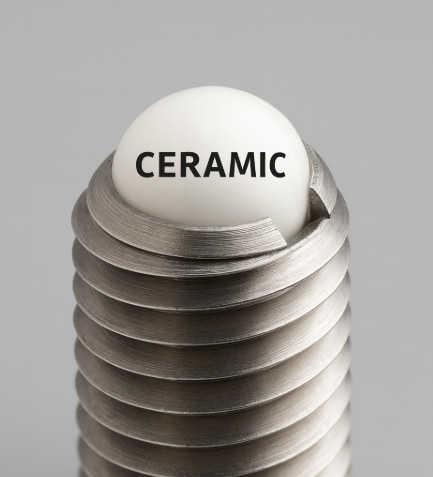
In recent years, ceramic balls have also become available. Ceramic balls are non-magnetic and electrically insulating, and they offer excellent corrosion and heat resistance, making them suitable for harsh environments such as medical, electronics, and marine applications.
Another advantage of ceramics is their low coefficient of friction, enabling smooth operation along with durability.
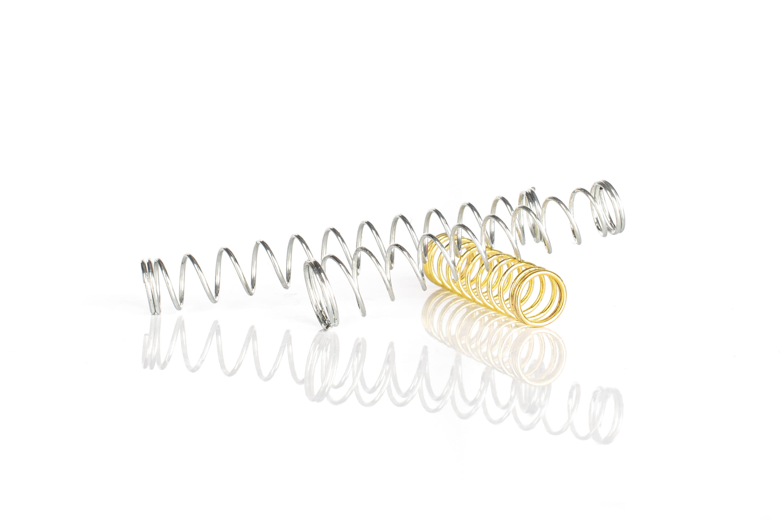
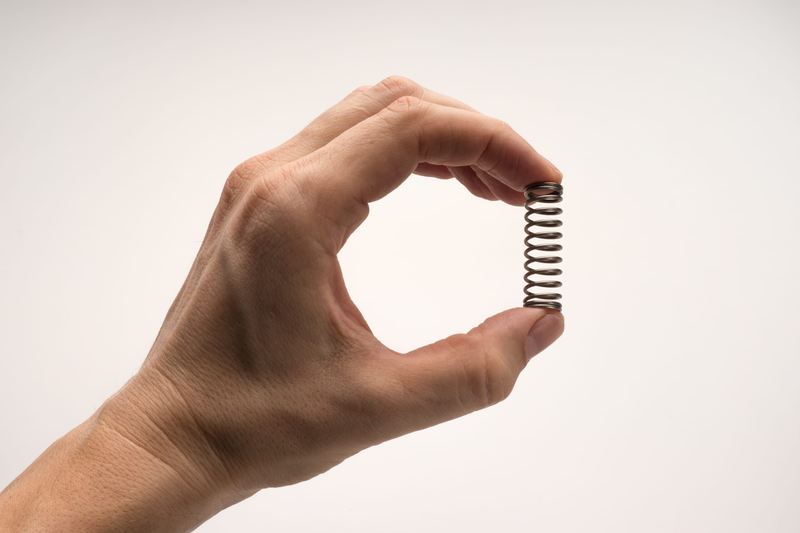
Springs are typically made of piano-wire spring steel or stainless steel.
Spring-steel springs provide a high elastic limit and low cost, but they require measures such as an oil film or plating for rust prevention. Stainless springs are more corrosion-resistant and maintain stable elasticity over long periods, making them suitable for outdoor or high-humidity environments.
Depending on the product, two versions may be offered—standard load (lighter spring) and heavy load (stronger spring). Because the pressing force can be adjusted by changing wire diameter and coil turns, users must select the spring strength that matches the required pressing force.
Material selection is driven by durability, environmental resistance, and application requirements.
For example, in positioning applications with repeated friction, a hardened steel ball combined with a steel body helps secure wear life.
In contrast, food machinery and medical equipment often use stainless steel or plastics for all components to prioritize corrosion resistance and cleanability. For fixtures used with electrical parts, non-conductive materials (plastics or ceramics) may be used for the ball and/or body to prevent electrical conduction through metal-to-metal contact.
In assembly equipment where wear debris or noise is undesirable, plastic balls and plastic bodies may be used to achieve quiet, clean operation even without lubrication.
In this way, ball plungers can be tuned for properties such as durability (service life), corrosion resistance, and noise reduction through material selection for each component.
Purpose and Typical Applications of Ball Plungers
Ball plungers are mainly used for positioning objects and providing temporary holding.
The spring force seats the ball into a defined location on the mating part (detent), allowing the positional relationship between components to be reproduced accurately and repeatedly.
In rotating or sliding mechanisms, they can also function as a notch that “clicks” into discrete positions, providing tactile feedback.
Beyond positioning, ball plungers can also apply a constant side force to press an object against a guide rail, or serve as a stopper to prevent parts from falling out.
Typical applications include the following.
Securing and Clamping Adjustment Parts
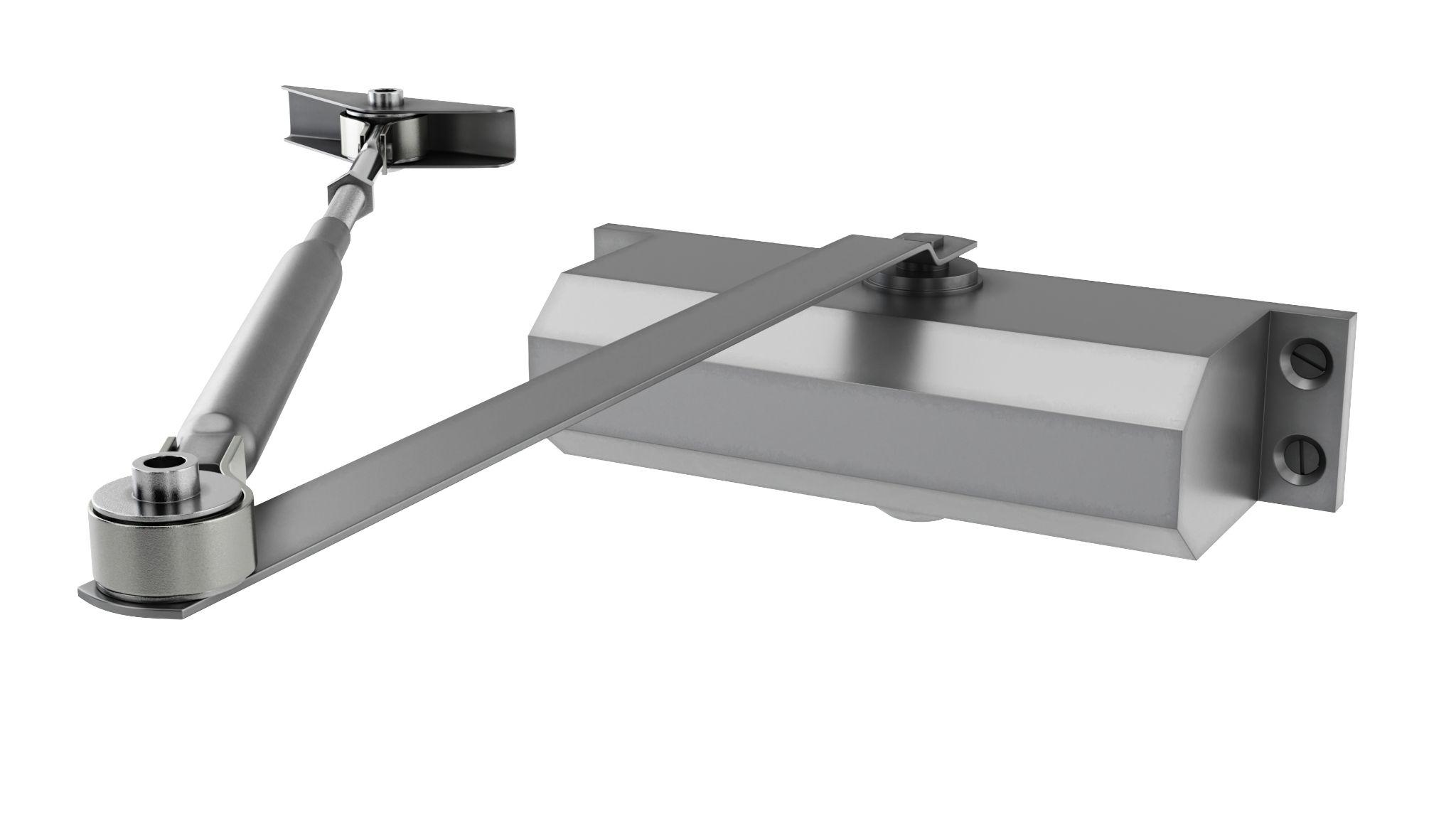
In adjustment mechanisms such as movable arms and rotary knobs, a ball plunger can latch (engage) at a defined position so it will not come loose from normal vibration.
When needed, the position can be changed by hand or with force above a certain threshold, allowing readjustment.
They can also be used to locate detented positions on angle-adjustment levers or to provide pin-like holding in protractor mechanisms.
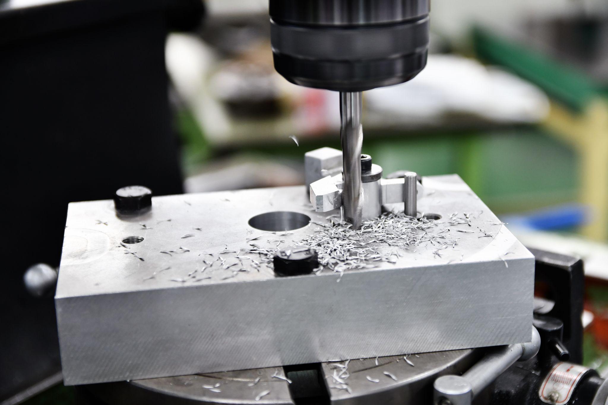
Locating Fixtures and Workpieces
They are used on machining or assembly fixtures to repeatedly locate workpieces and detachable parts in a defined position.
By embedding a ball plunger in the fixture and letting the ball seat into a corresponding hole or groove on the workpiece, it functions as a simple locating punch or hold-down.
Compared with locating pins, installation is easier, and it is well-suited to small parts.
Automated workpiece centering and positioning
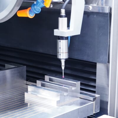
- Touch-probe -
a contact/touch sensor for on-machine measurement that improves the efficiency of setup work
Click here ›Latching Mechanisms for Sliding Parts

In sliding mechanisms such as drawers and movable guides, they are used as latches to temporarily hold a defined position.
A recess is provided on the rail side for the ball plunger to seat into, stopping the slide at that position. This simple locking mechanism is also applied to lids and cover parts that require manual removal or disassembly.
Transfer Guides and Side Pressing
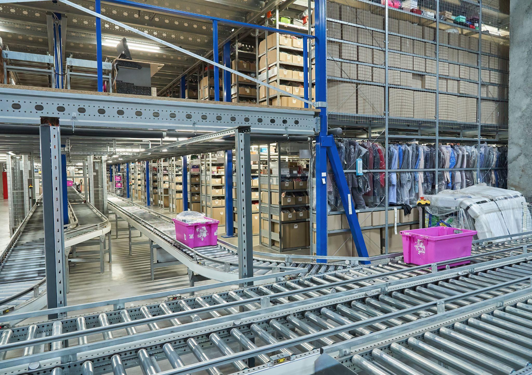
In conveyors and transfer equipment, they apply side pressure via spring load to bias workpieces to one side or guide them into the correct position.
One example is arranging ball plungers along the side of a belt conveyor to press passing parts against a guide with a constant force, aligning their orientation.
If the ball tip contacts while rotating, it is less likely to damage parts and enables smooth transfer.
Key Considerations When Selecting a Ball Plunger
When selecting a ball plunger, you need to evaluate several technical factors to confirm the specifications match your objective.
The main evaluation items are summarized below.
Spring Load (Pressing Force)
The pressing force generated by the plunger (end force) is the most important selection factor.
Product catalogs list the initial load when the ball is fully projected and the maximum load at full depression.
In general, larger sizes provide stronger spring forces: small models may be only a few newtons (N), while larger models can reach tens to hundreds of newtons. One product line, for example, ranges from a minimum of 0.125 lb (approx. 0.56 N) up to 68 lb (approx. 302 N).
Therefore, it is important to choose a model with a spring load that matches the required holding force and the desired “click” feel during operation.
If both light-load and heavy-load versions are available in the same size, select the appropriate one for your application.
Excessive spring force can make operation stiff and accelerate wear, while insufficient force may cause issues such as disengagement due to vibration.
Ball Projection and Stroke
Also confirm the height the ball projects from the body (projection) and the displacement when pressed in (stroke).
If projection is insufficient, engagement into the mating hole becomes shallow and adequate retention cannot be achieved.
Conversely, too much projection can cause interference during assembly.
Since catalogs specify ball diameter and projection height, verify that dimensions will engage properly with the mating hole depth and plate thickness.
Because spring load changes with compression (increasing as compression progresses according to the spring rate), also understand the load at the actual pressed-in position in use (intermediate load).
For example, with a spring rated 4 lbs initially and 12 lbs at full depression, the load at half stroke would be about 8 lbs.
Since this intermediate load becomes the effective engagement force, designs should be based on that condition.
If the ball is pressed in too far and the coil spring goes solid, there is no remaining compliance and damage may occur, so use the product within the maximum stroke specified in the catalog.
Size (Thread Diameter / Body Diameter / Length)
Determine the plunger size based on mounting space and the dimensions of the mating part.
For threaded types, thread diameter and pitch are standardized; for press-fit types, body diameter and length are standardized.
In general, smaller models tend to have shorter stroke and lower load, while larger models tend to have longer stroke and higher load, so balance required performance against installation space.
If the plate thickness at the mounting hole is thin, the body length may not match and projection may be insufficient, so consider a short plunger for thin sections (e.g., a stubby type).
If standard products do not fit, consider adding spacers or using custom parts.
Selecting a Mounting Method
As noted above, choose between threaded and press-fit types based on design constraints.
Threaded types are preferable when frequent replacement or adjustment is required for maintenance, while press-fit types may be favored for mass-production fixtures where simplified assembly and low cost are priorities.
For threaded types, also consider whether the thread size can be standardized with surrounding fasteners and whether there is adequate tool access for tightening.
For press-fit types, pay attention to press-fit hole machining accuracy and re-insertability (typically one-time use).
Material Compatibility
As discussed in the materials section, select the best material configuration based on the operating environment and the relationship with the mating component.
Consider stainless steel in humid or chemical environments; plastic or aluminum bodies if weight reduction or non-magnetism is required; and ceramic-ball products for high-temperature or cleanroom applications.
If the mating part is soft (e.g., aluminum or plastic), you may need measures such as using a nylon ball to prevent indentation, or embedding a hard bushing in the mating part to receive a steel ball.
If you must avoid creating an electrical path, use a plastic plunger or a type with an integrated plastic bearing to ensure electrical insulation.
Also consider the combination of contacting materials (e.g., from the perspective of galvanic corrosion) and how easy the assembly will be to clean.
Repeatability and Durability (Service Life)
The repeated durability of the spring and ball is also important.
High-quality products are said to withstand several thousand operating cycles, but actual service life depends on design and operating conditions.
Especially in applications with high-speed, frequent engagement, wear debris and spring set can be concerns, so consider products using self-lubricating materials (plastic bearings) and maintenance such as periodic re-greasing.
In environments where dust or chips can enter clearances and hinder movement, service life may decrease, so consider adding dust covers and performing regular cleaning.
Near end of life, the ball tip may lose smoothness and spring load may decrease, so it is recommended to build appropriate replacement timing into the design from a preventive maintenance perspective.
As described above, ball plunger selection requires an integrated evaluation of mechanical requirements (load and stroke), physical constraints (size and mounting method), and environmental requirements (materials and durability).
By selecting a product with appropriate specifications, you can achieve stable locating and retention performance over the long term.
High Precision Positioning
- Ball Plunger Switch Sensors -
Indexing by ball plunger and confirmation signal output. Reduce the number of parts to make smaller machines at lower costs.
Click here ›Practical Advice for Designers
Below is a set of practical know-how and cautions to help manufacturing product designers apply ball plungers effectively in real work.
Designing an Appropriate Detent Geometry
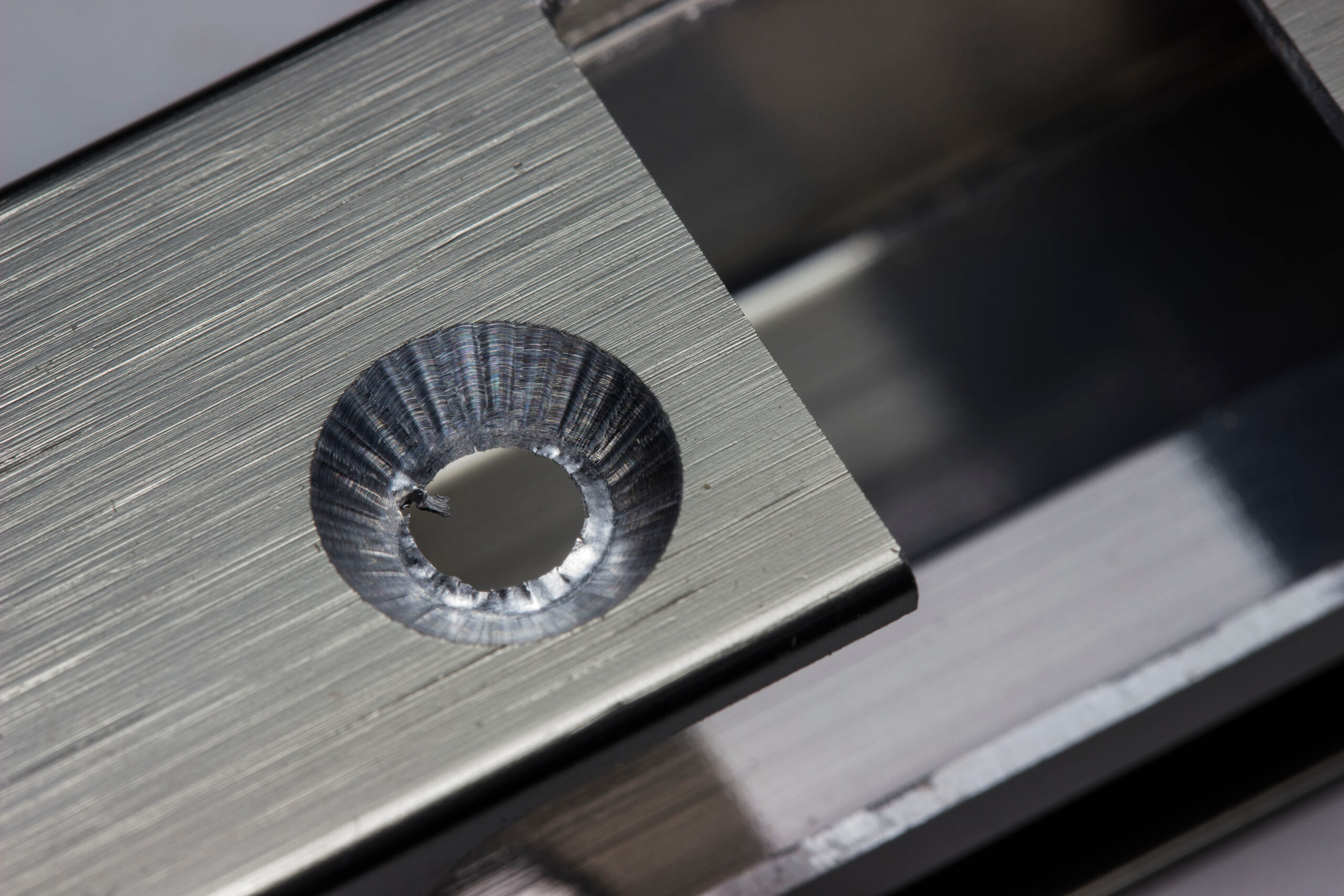
The geometry and angle of the mating hole or groove that the ball engages with affects retention force.
A shallower (flatter) countersink angle makes the ball easier to release, while a deeper angle provides stronger holding.
A countersink around 90° is commonly used, but adjust the angle based on the required retention force.
Also, tapering the hole so the depth is about 60–70% of the ball diameter helps the ball catch reliably while still releasing smoothly.
If the mating part material is soft, repeated use can enlarge the hole and reduce retention. Press-fitting a hardened-steel bushing as the detent seat can be an effective countermeasure.
Load Setting and Safety Factor
Use the catalog’s initial and final load values as references and select a model that matches the required pressing force in actual use.
Too little force risks disengagement due to vibration, while too much force requires higher operating effort and can damage parts.
If you are uncertain, one approach is to choose a slightly higher load and fine-tune retention via the detent hole slope.
For critical holding points, adding a safety factor to account for long-term spring force reduction can provide peace of mind.
Conversely, for mechanisms frequently operated by people, prioritize usability and select the minimum necessary load to reduce fatigue and help prevent misoperation.
Material and Lubrication Measures
In environments where wear or rust is a concern, address the issue through material selection and lubrication.
For machines where chips are present, a stainless-steel body combined with a dry lubricant can help prevent rust and dust adhesion. In cleanrooms, using a ceramic ball with fluorinated grease can suppress fine particle generation and wear.
Filling with grease is effective for rust prevention and noise reduction, but if oils must be avoided, consider solid lubricant coatings such as molybdenum disulfide.
During periodic maintenance, blowing off dust with air and applying fresh lubricant can extend service life.
Mounting and Implementation Tips
For threaded types, one option is to screw the plunger in to the specified torque before assembly where possible, and apply a thread-locking compound to improve retention.
With press-fit types, operators may press them in at an angle, so use a jig to press them in perpendicular to the surface. Deburr the press-fit hole carefully; even a small burr can cause binding and prevent insertion to the proper position.
If multiple plungers are arranged in series, also pay attention to the cumulative error of their positional tolerances.
Applying a drop of rust-preventive oil to the ball area after assembly can also improve initial run-in.
Comparing Alternatives
Because ball plungers are not a universal solution, it is important to compare them with other mechanisms.
For example, where secure locking is required, a threaded spring pin or locking bolt may be more suitable.
If only a small pressing force is needed, detents using leaf springs or magnets can be alternatives.
Ultimately, always evaluate whether a ball plunger is the best solution for the required performance and cost.
Especially in mass-produced products, even small per-unit cost differences add up, so selecting components with “just enough” specifications is important.
Advantages of Using Ball Plungers for Workpiece Locating in Fixtures
By using ball plungers for locating on fixtures for line-processed parts, even less-experienced operators or part-time workers can position workpieces easily. In addition, by reviewing fixture design and machining sequence, using ball plungers can sometimes help prevent missed processes and the generation of defective products.
If holes or grooves machined in an earlier process are used for ball-plunger locating, then attempting to mount the workpiece while skipping a process will prevent proper positioning. This makes mounting mistakes easier to notice and helps prevent errors such as unintentionally machining while skipping a step.
When using machined holes for locating, it is recommended to use areas with stable hole diameters, such as reamed holes, and to avoid threaded holes where possible.
Also, when using machined holes for locating, choose a type with a spring force that is not excessively strong.
If the spring force is too strong, the hole edge (mouth) may deform.
Even when you must use threaded holes, be aware that excessive spring force can cause problems such as bolts no longer fitting after machining.
Automated workpiece centering and positioning
- Touch-probe -
a contact/touch sensor for on-machine measurement that improves the efficiency of setup work
Click here ›Clean the Ball Plunger Tip Regularly
When ball plungers are used on fixtures for machining centers and similar equipment, cutting fluid and fine chips can adhere to them and degrade the ball’s movement at the tip.
Cutting fluid in particular becomes more viscous when it dries, and in ball plungers with low spring force the ball can sink inward and seize in place.
If left as-is, chips may enter the interior and render the plunger unusable. Therefore, be sure to clean the tip regularly or before removing/attaching (replacing) the fixture, and apply clean lubricating oil or rust-preventive oil.
While ball plungers themselves are not very expensive, replacement often requires fine adjustment of the projection.
Additionally, if thread-locking compound is used to secure the ball plunger, replacement can require additional effort, work, and time.
To avoid such hassles, keep the ball plunger tip clean by washing it regularly.
What Are Metrol’s High-Precision Positioning Sensors?
In machine tools and automated lines, whether a workpiece can be placed accurately has a major impact on machining accuracy and productivity. Metrol’s high-precision positioning sensors are trusted in such environments.
With an impressive maximum repeatability of 0.5 µm and waterproof/dustproof performance, they operate reliably even in harsh environments.
Here is an introduction to Metrol’s sensors, which are chosen by many manufacturing sites.
High-Precision Positioning Touch Switches
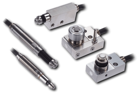
These are contact-type high-precision switches used for positioning and workpiece presence detection in machine tools, robots, and jigs. They achieve an extremely high repeatability of up to 0.5 µm and feature IP67-rated waterproof and dustproof protection, ensuring stable operation even in harsh environments. With more than 200 standard models available, they offer a wide range of variations, including designs for confined spaces, high-temperature environments, vacuum applications, and low contact force requirements.
Tool Setter (Tool Length Measurement Sensor)
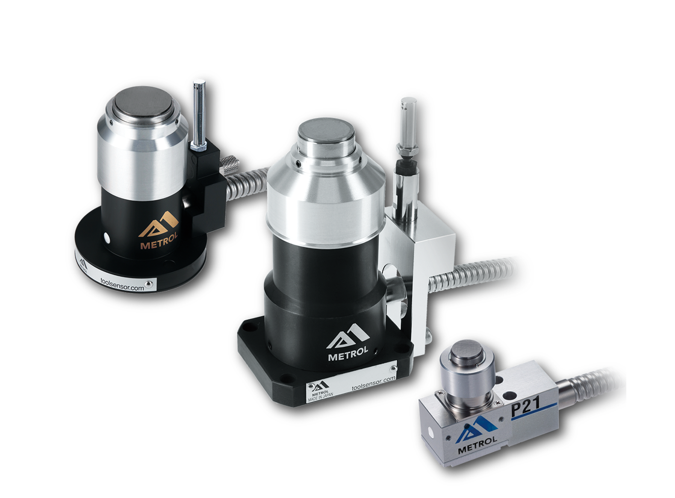
This is a contact-type sensor installed on CNC machine tools and industrial robots for tool length measurement, reference position setting, and tool breakage detection. By automatically measuring and compensating for tool length, wear, and thermal displacement inside the machine, it helps prevent machining defects and significantly reduces setup time. It is one of Metrol’s best-selling products, with a proven track record of more than 500,000 units shipped in 74 countries worldwide.
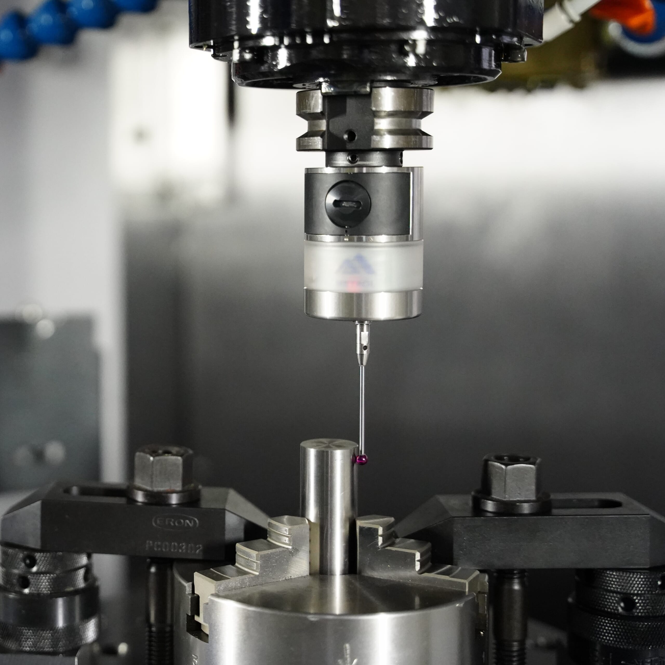
Touch Probe (On-Machine Measurement Probe)
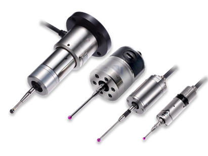
This is a contact-type probe for in-machine measurement, installed on machine tools and robots to automatically perform workpiece positioning (centering) before machining and dimensional measurement after machining. With a repeatability of 1 µm, it automates workpiece referencing and dimensional inspection, replacing skilled manual operations to reduce setup time and help prevent machining defects. Both wired and wireless models are available, meeting retrofit needs for 5-axis machining centers and robotic applications.
Air Gap Sensor (Pneumatic Sensor)
This is a non-contact sensor that uses air pressure to detect workpiece seating conditions with micron-level accuracy. It can detect gaps (“lift”) of less than 10 µm—previously difficult to measure—with a repeatability of ±0.5 µm, helping prevent machining defects and equipment downtime caused by insufficient contact between the workpiece and fixture. The sensor is used in applications such as semiconductor manufacturing processes, precision part clamping operations, and grinding wheel positioning on grinding machines, and it is a smart sensor that also supports the international standard IO-Link communication.