What Is Clamping? Basic Principles and Types of Workholding for Machine Tools, and Safe Operation Tips from the Shop Floor
Workholding clamping is a foundational technology that determines both machining accuracy and shop-floor safety. In cutting operations on machining centers and lathes, securely fixing the workpiece enables high-precision machining while protecting operators at the same time.
A wide range of methods—from mechanical clamps to the latest zero-point systems—are selected according to the application. Their importance continues to grow as high-mix, low-volume production and factory automation advance.
This article explains the fundamentals of clamping and the characteristics of each method, along with practical selection criteria, automation readiness, and proven know-how to prevent issues—knowledge that’s genuinely useful on production floors.
Table of Contents
What Workholding Clamping Is: Its Role and Importance
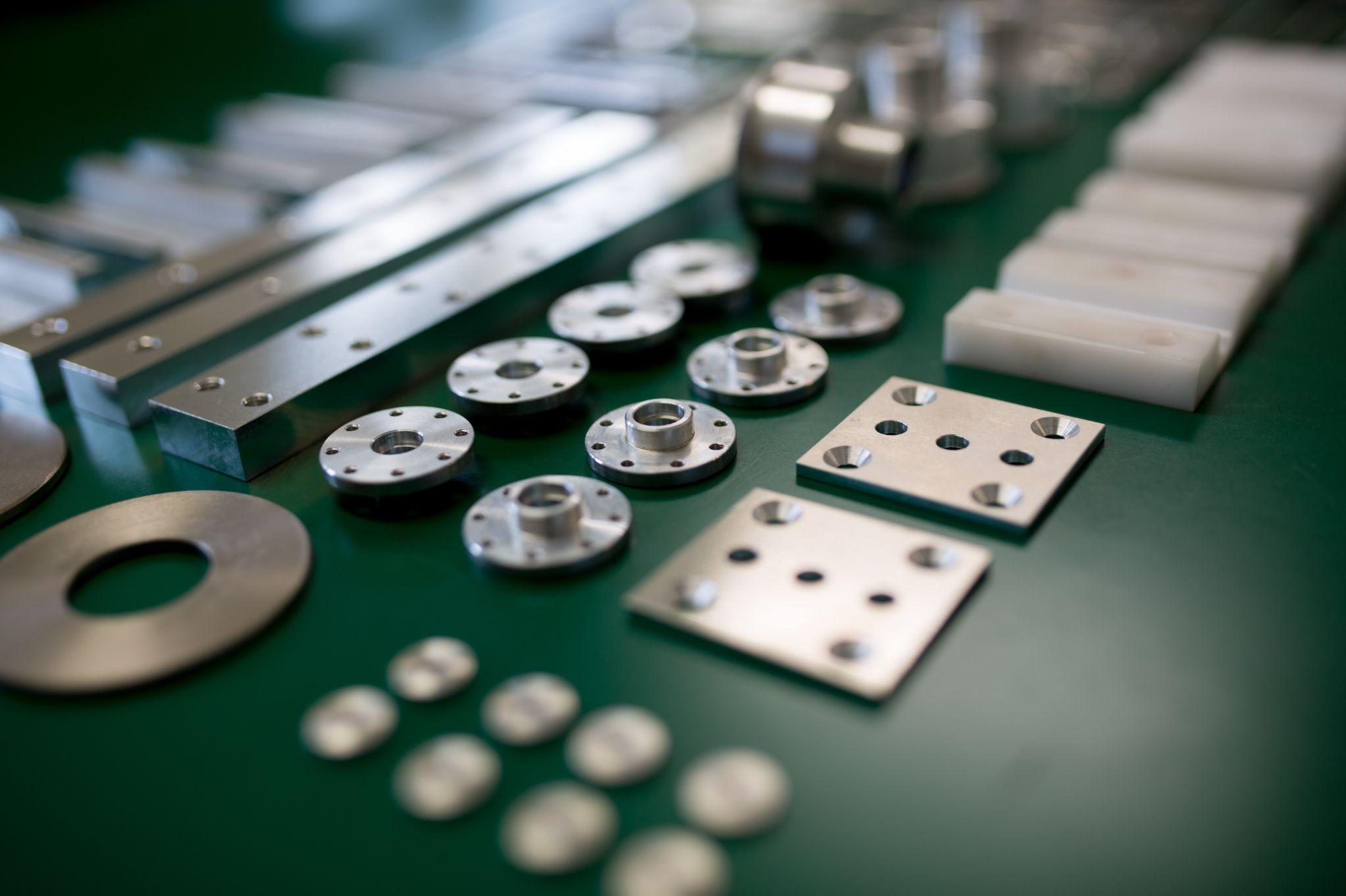
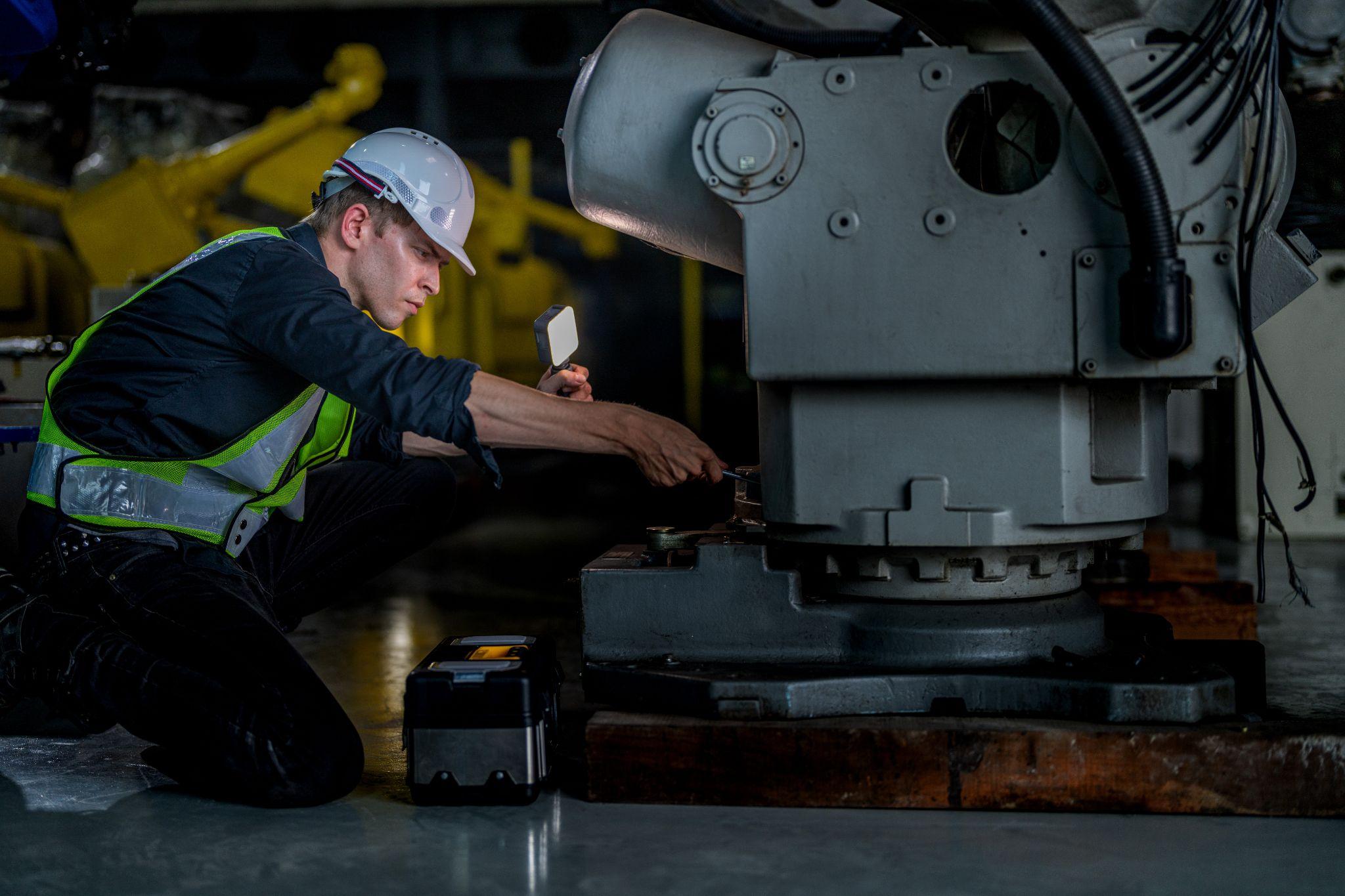
In machine tools, “workholding clamping” refers to devices used to firmly secure a workpiece (the material or part to be machined) during operations on machining centers, milling machines, lathes, and more. Clamping performs both locating and tightening so the workpiece does not move during machining, ensuring high accuracy and repeatability.
If you choose a sufficiently strong clamping method, you can prevent dimensional errors caused by slight runout or vibration during cutting and stabilize machining quality. Conversely, insufficient fixturing can allow the workpiece to shift during machining—or in the worst case, fragments of the workpiece or tool may scatter and endanger operators.
For this reason, workholding clamping is a “behind-the-scenes powerhouse” in machine tools, playing a crucial role in both productivity and safety.
Proper clamping also helps shorten setup/changeover time and reduce costs, making it a key lever for improving productivity in manufacturing. Below, we explain the main clamping methods and types, selection points, the latest trends, and considerations for safe operation.
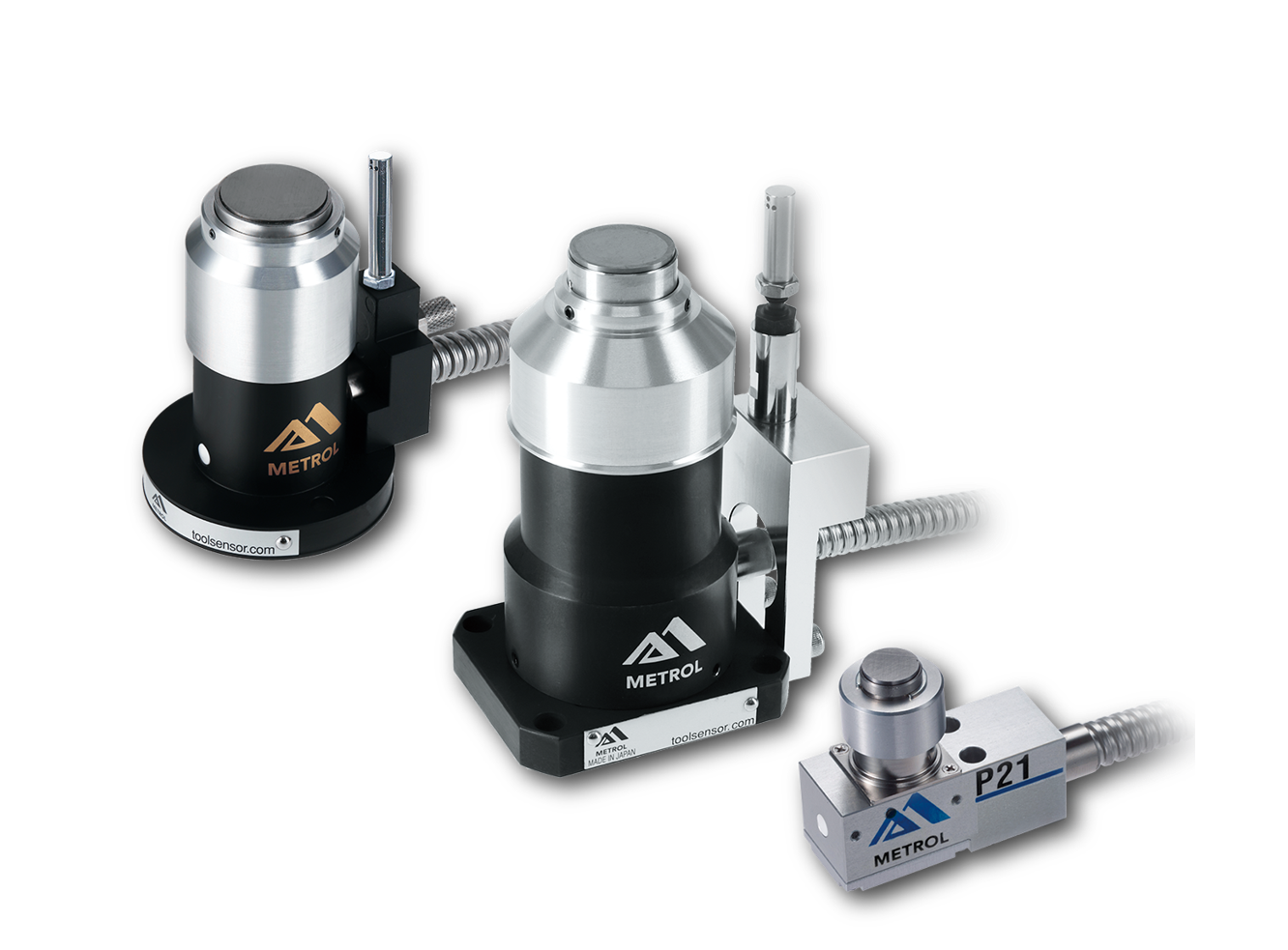
Automated workpiece centering and positioning
- Touch-probe -
a contact/touch sensor for on-machine measurement that improves the efficiency of setup work
Click here ›Main Types of Workholding Clamps and How They Work
There are many types of workholding clamps used in machine tools, each with different mechanisms and characteristics. Below are representative approaches.
Mechanical Clamps
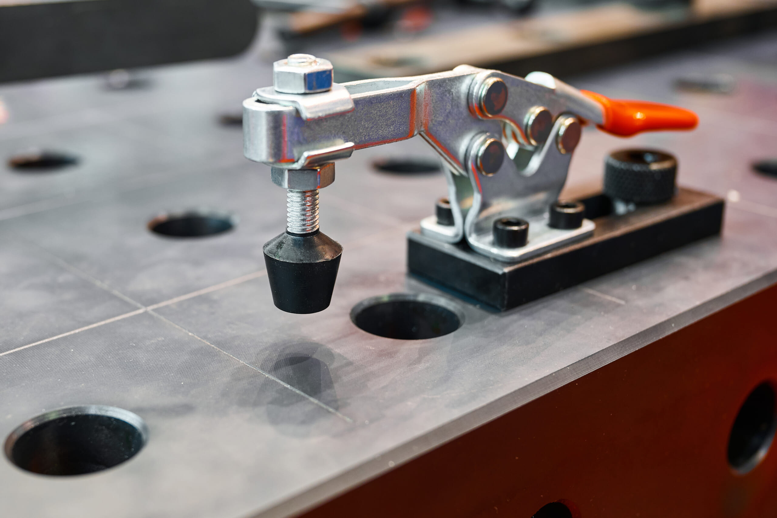
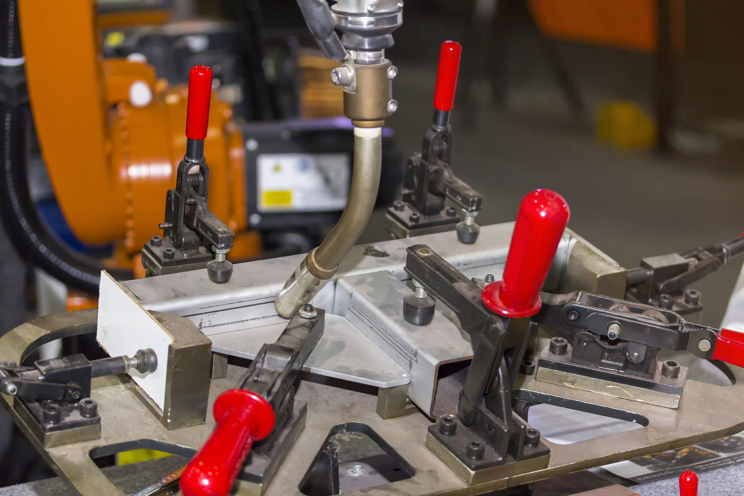
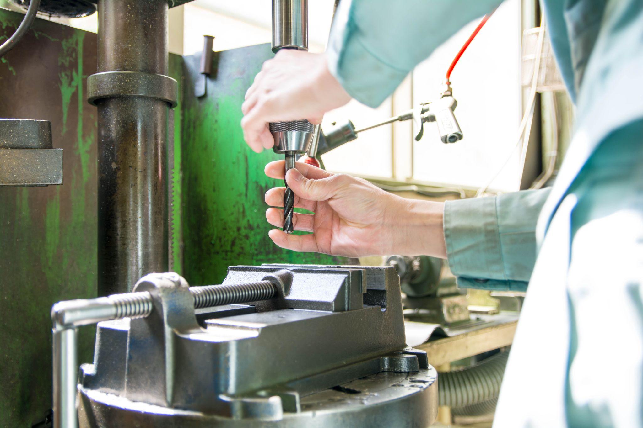
Mechanical clamping uses mechanical force—such as screws or levers—to tighten and hold a workpiece. Typical examples include vises used on machining centers, lathe chucks, clamp sets bolted into T-slots, and toggle clamps (lever-type clamps).
By tightening bolts or turning a handle, operators generate a strong clamping force to secure the workpiece. With a simple structure, broad versatility, and relatively low cost, this is the most widely used method.
On the other hand, because attachment and removal are generally manual, setups can take time, and complex-shaped workpieces may require dedicated fixtures. Even so, for low-volume production or simple machining, mechanical clamps remain mainstream due to their convenience and cost-effectiveness.
Pneumatic Clamps
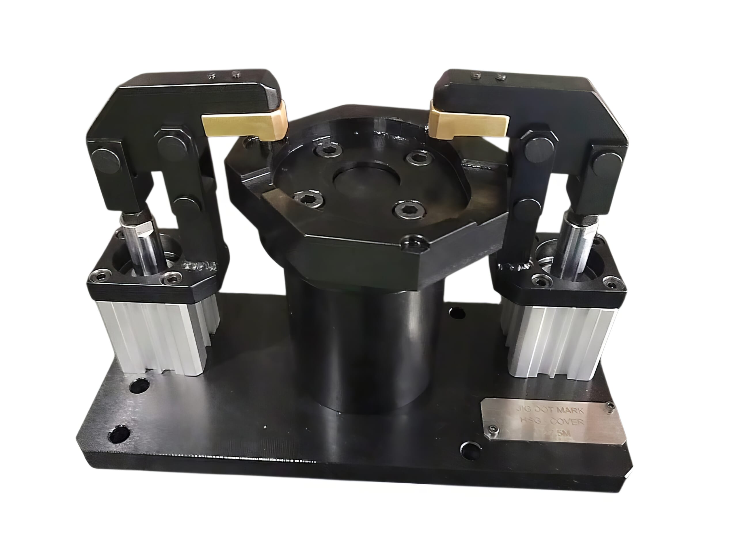
Pneumatic clamping uses compressed air to clamp and release a workpiece. Examples include air-driven vises powered by pneumatic cylinders and swing clamps whose arms rotate automatically to press the workpiece.
A key advantage is one-touch operation using an air supply, enabling fast automatic clamp/unclamp via buttons or program control. Compared with mechanical methods, pneumatic systems more easily reduce labor and support simultaneous multipoint clamping, making them suitable for automated lines and mass production.
For example, pneumatic clamping can tighten multiple workpieces at once or automatically attach/detach them based on robot commands. However, because the maximum clamping force is not as high as hydraulic systems, care is needed for extremely heavy workpieces or processes requiring very high holding force.
While an air source and piping are required, pneumatic clamping is widely used as a practical automation method because it avoids oil leaks and is generally easy to maintain.
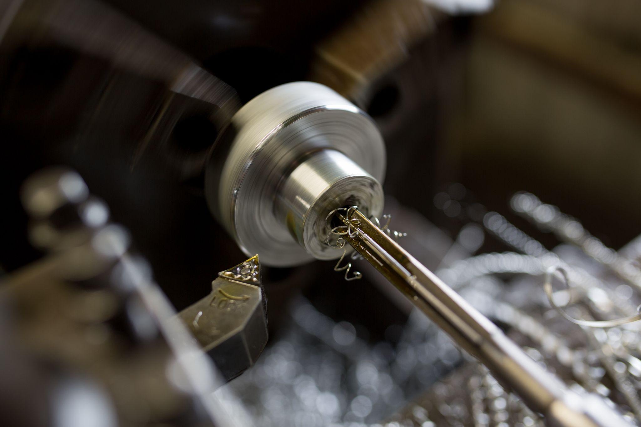
Hydraulic Clamps
Hydraulic clamping uses hydraulic pressure to firmly clamp a workpiece. This includes hydraulic chucks, hydraulic vises, and fixtures with built-in hydraulic cylinders.
High-pressure oil generated by a pump is delivered to the clamping unit, and the workpiece is gripped by piston force. The defining features are very high clamping force and stability, allowing robust fixation even for large, heavy, or complex-shaped workpieces. The uniform force provided by hydraulics also improves repeatability in locating, contributing to higher machining accuracy. For example, in simultaneous machining of automotive parts, many workpieces may be clamped together hydraulically and held with high rigidity.
On the downside, systems can be expensive, and auxiliary equipment such as hydraulic power units and piping is required—raising barriers in terms of initial investment and maintenance.
Even so, hydraulics are indispensable for large workpieces and high-precision machining, and in recent years many fixtures for automated lines have been put into practical use, controlling numerous clamps via a centrally managed hydraulic source.
Although the upfront cost is higher, hydraulic clamping significantly improves productivity through its powerful holding force and high accuracy.
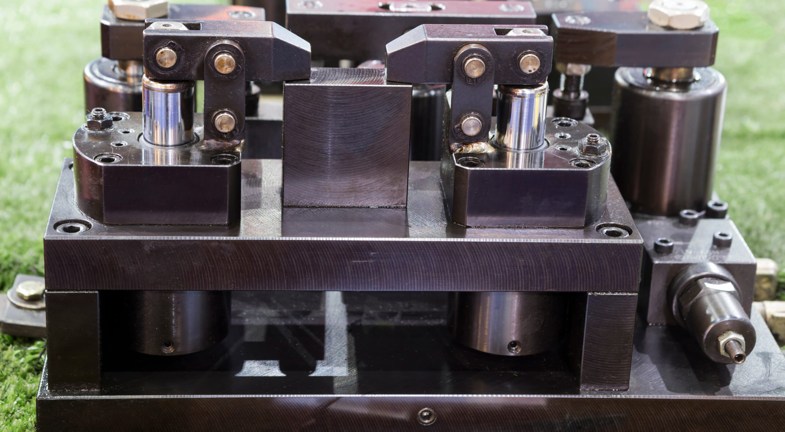
Modular Clamps (Modular Fixtures)
Modular clamping refers to a modular workholding system that can be reconfigured depending on the application. On a pre-drilled grid plate (fixture plate) or rails, various clamping elements—such as stoppers, clamping blocks, and bolts—can be freely positioned to secure the workpiece.
The biggest feature is flexibility: like LEGO blocks, you can change the configuration to respond quickly to workpieces of different shapes and sizes. If you have a set of modular fixture components, you can build the required setup by simply adjusting positions and the overall arrangement for a new workpiece.
Fast changeovers are a major advantage, reducing machine downtime and boosting productivity. Because standardized components are combined, cost efficiency is also strong, and expansion is easy by adding parts as needed.
Modular clamping is especially effective for high-mix, low-volume production and prototype machining, and in recent years advanced modular fixture systems for 5-axis machining centers have also emerged.
Because even non-experts can build fixtures quickly, modular clamping is gaining attention as a method that achieves both flexibility and higher productivity.
Magnetic Clamps
Magnetic clamping uses magnetic force to attract and secure a workpiece. Often called a “magnetic chuck,” it is mainly applied to ferromagnetic workpieces such as steel.
Because electromagnetic or permanent-magnet force (including electro-permanent magnets) holds the workpiece to the table, a major benefit is that the workpiece can be secured without physically pressing on its surface with clamp hardware.
As a result, for example, clamping a flat plate with a magnetic system can reduce distortion caused by mechanical clamping and enable higher-precision machining.
This is particularly effective when machining thin steel plates to prevent deformation. Some reported cases note that “thin plates that warp with other clamps saw dimensional errors greatly reduced when using a magnetic chuck.”
Because clamp hardware does not obstruct access, magnetic clamping pairs well with 5-sided and 5-axis machining and can also reduce the number of changeovers.
Limitations include the inability to use it on non-magnetic materials (such as aluminum, copper, or resins) and the possibility of insufficient holding force when the workpiece is extremely heavy or the contact area is small. Some operators feel uneasy because magnetic force is invisible, but modern electro-permanent magnetic chucks can retain magnetic force even during a power outage, improving safety.
In summary, magnetic clamping excels at high-precision machining of thin or flat plates and holding over a wide surface area, but suitability is clearly dependent on material and geometry.
Zero-Point Clamps (Zero-Point Clamping Systems)
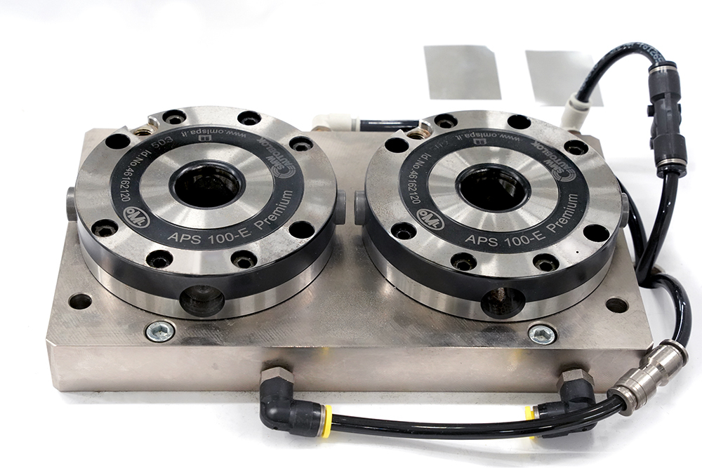
Zero-point clamping systems are a recently popular clamping mechanism that enables rapid attachment, removal, and exchange of workpieces or fixtures on the machine. Reference holes or pins—the “zero points”—are prepared on the machining center table, and dedicated clamping bolts (pull studs) mounted on the workpiece or fixture are inserted and locked into those reference points for near-instant fixation.
For example, if multiple zero-point receivers are embedded in a table, you can mount the next fixture plate with a one-touch operation when swapping workpieces—without the time-consuming steps of locating and bolt tightening.
This dramatically reduces machine setup time and minimizes line downtime. Inside the zero-point clamp, a locking mechanism—such as a wedge mechanism—pulls in the stud strongly. Once clamped, it provides high repeatability in positioning and powerful holding force.
Another feature is modularity: the system can be flexibly expanded and adapted by combining height-adjustment elevator blocks or adapter plates as needed. Actuation types vary—mechanical (manual tightening), pneumatic, hydraulic, electric, and more—so it is used broadly from manual setups to automated production lines.
In recent years, zero-point clamping has increasingly been integrated into automated processes. By adopting it as the interface between machine tools and robots, it has become common to set up the next workpiece externally and then swap it quickly during unmanned operation.
Although it requires initial investment, zero-point clamping is a decisive productivity booster in high-mix, low-volume environments and shops with frequent changeovers, thanks to outstanding setup efficiency and repeatable accuracy.
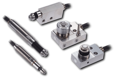
High Precision Positioning
- MT-Touch Switches-
0.5 μm repeatability without amplifier IP67, highly resistant to adverse environments
Click here ›Key Points for Selecting Workholding Clamps (Selection Criteria)
When selecting workholding clamps, it is important to choose the best method and model for the workpiece and machining conditions. Below are typical decision criteria.
Workpiece Shape and Size

The appropriate clamp depends on whether the workpiece is square or round, large or small. For prismatic parts, a standard vise may be sufficient, but cylindrical parts typically require a chuck or collet that grips the outside or inside diameter, or a V-block, for example.
Workpiece dimensions must also be considered. If the part is too small for the clamp to reach, you may clamp multiple parts at once; if it is too large, you may add modular fixture elements. In short, selecting the “right tool for the job” according to workpiece size is essential.
Fixturing that does not match the geometry or dimensions can lead to unstable holding and cause accuracy defects.
Machining Process and Required Accuracy
The machining method, cutting load, and required accuracy directly affect clamp selection. For heavy cutting or roughing, you need robust clamping that withstands strong cutting resistance—hydraulic clamping or heavy-duty mechanical fixtures are suitable.
In 5-axis machining or finishing processes, it is also important that the clamp itself be compact so it does not obstruct tool access. If the clamp is too large, it can cause tool interference, so you must balance rigidity (stability) with machining accessibility.
When high precision is required, ensuring rigidity across the entire machining system is essential. High accuracy is achieved only when the rigidity chain—machine, tool, workpiece, and clamp—works as one. If the workpiece moves even slightly, you cannot achieve the intended dimensions.
In high-precision machining, choosing clamps with superior rigidity and accuracy—even at some added cost—often reduces defects and rework in the end.
Setup Time (Changeover Frequency)
The number of product types and lot sizes also influence clamp selection. If you handle many parts and changeovers are frequent, reducing setup time becomes extremely important.
For example, in high-mix, small-to-medium lot production where fixtures are changed multiple times per day, you need fast solutions such as pneumatic clamps, zero-point clamps, or modular clamping systems that enable one-touch attachment/removal.
Conversely, if you mass-produce a single product for long periods, a dedicated mechanical fixture can be sufficient because you can invest time in building a solid setup once and then keep running.
In this way, depending on the production style—high-mix, low-volume or low-mix, high-volume—the priority shifts between setup speed and holding force/accuracy.
Clamp Rigidity and Stability
The rigidity and holding force of the clamp itself are also key selection criteria. Without sufficient rigidity to prevent any workpiece movement during machining, you cannot achieve either high accuracy or safety.
For large workpieces or heavy cutting of difficult-to-machine materials, consider hydraulic or heavy-duty mechanical clamps. Also, if the workpiece has thin walls or is brittle, excessive clamping force can deform or damage it, so caution is required.
Clamping force is not simply “the stronger, the better.” You must select an appropriate force that matches the workpiece strength and rigidity. Depending on the case, consider hydraulic/pneumatic systems with adjustable pressure or the use of a torque wrench.
Repeatability and Locating Accuracy
Repeatable locating accuracy is also crucial when machining in multiple steps or swapping entire fixtures. For example, whether you can reclamp in the same position and orientation after unclamping directly affects product accuracy and whether machining can continue as intended.
With systems that inherently provide high repeatability—such as zero-point clamping—this is less of a concern. However, even with standard vises, you should improve repeatability by using locating keys or stop blocks.
Especially in multi-part machining (processing multiple workpieces at once), inconsistencies in each workpiece’s position can cause variation in results. If accuracy is the priority, consider high-precision fixtures or a zero-point system.
High-precision seating confirmation of workpiece and jig
- Air Gap Sensor -
you can check not only "presence/absence" but also "adhesion (gap)" at the same time with a repeatability of ±0.5μm.
Click here ›Ease of Attachment/Removal (Setup Efficiency)

In real operations, the ease of setting and removing a workpiece cannot be ignored. If the fixture requires complex bolt tightening, every attachment/removal takes time and can lengthen cycle time.
In processes with frequent workpiece swaps, choose clamps equipped with mechanisms that enable rapid attachment/removal, such as quick-change mechanisms or cam-lever clamps.
In recent years, more clamps incorporate actuators that allow one-touch release. Selecting products with high setup efficiency—while keeping future automation in mind—can ultimately reduce labor and man-hours over time.
Safety
Safety of the clamping method and procedure is also a top priority. For example, when securing heavy workpieces, a loose clamp can lead to a serious accident.
Therefore, it is advisable to select on the safe side—such as using clamps with safety valves or double-lock mechanisms, or hydraulic clamps that automatically lock when pressure drops.
Also consider whether the design allows safe operation—e.g., whether there is a risk of pinching hands, and whether operators can avoid manually handling heavy objects.
In recent years, systems that detect clamping completion with sensors and systems that monitor tightening force and alarm when it is insufficient are also becoming practical. Choosing clamps that prevent human error and hold workpieces safely and reliably directly improves shop-floor confidence and productivity.
Clamp Automation Technologies and Robot Integration
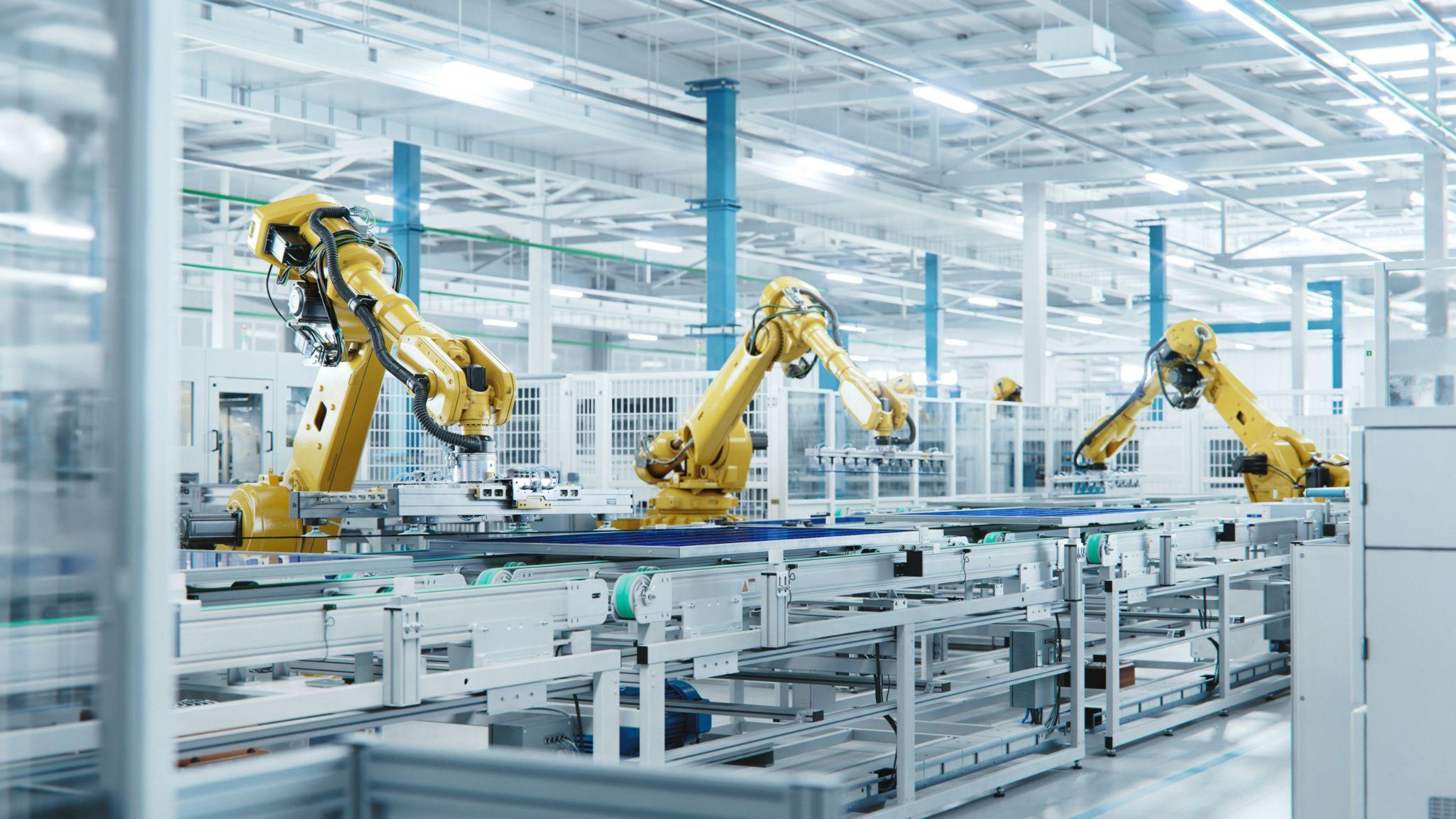
With advances in factory automation and robotics, automation trends are accelerating in the workholding field as well. Systems are increasingly being adopted in which machines automatically perform workpiece loading/unloading and clamping operations that were previously done manually.
For example, a robot arm can load a workpiece into a machine tool, place it on a fixture, and the clamp can then be automatically tightened by machine command—an end-to-end flow that is fully achievable. In automated lines, clamps must operate quickly and reliably. By minimizing human intervention, setup time is reduced and productivity improves. As a result, pneumatic and hydraulic power clamps are widely used, and it is easy to switch multiple clamps on/off simultaneously via machine control signals.
In practice, a key issue in automation is “how to achieve automatic clamp opening and closing,” and many manufacturers offer clamp devices with air cylinders or built-in electric actuators. In recent years, there has also been a shift toward replacing hydraulically driven clamps with electric motor-driven systems.
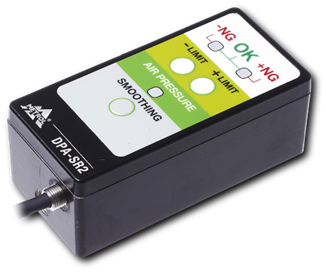
Electric clamps help enable clean and safe automation because they eliminate oil-leak risk and often improve energy efficiency. In robot integration, sensing the clamp state is indispensable. It has become common to detect whether the clamp is fully closed or open using air-pressure sensors or limit switches and feed back whether the next process can proceed.
For example, some pneumatic clamps include ports or switches that detect tightening and release, enabling confirmation that clamping has been performed correctly. In this way, smart factories where machine tools, robots, and clamps are seamlessly connected are becoming a reality.
The spread of collaborative robots (cobots) is also accelerating clamp automation. Because cobots can work alongside people, hybrid automation is possible—for example, a cobot receives a workpiece set by a person and places it into a clamp. Coordination between automatic clamps and robots is advancing in ways that are easier for small and mid-sized manufacturers to adopt.
Looking ahead, clamps themselves are expected to become more intelligent. Research is progressing on clamps with built-in sensors that numerically monitor clamping force, as well as adaptive clamps that automatically change shape and dimensions to match the workpiece geometry.
This makes next-generation smart clamping more realistic—clamping with the proper force without relying on operator intuition, and flexibly handling diverse workpieces. Clamp automation and intelligence are still evolving, and they will significantly contribute to labor reduction and higher efficiency on production floors.
High-precision seating confirmation of workpiece and jig
- Air Gap Sensor -
you can check not only "presence/absence" but also "adhesion (gap)" at the same time with a repeatability of ±0.5μm.
Click here ›Issue Prevention, Safe Operation, and Maintenance/Inspection Tips from Experienced Practitioners
To operate workholding clamps safely and prevent problems, daily control and periodic maintenance are essential. Finally, here are key points to keep in mind on the shop floor.
Correct Clamping Procedures and Safety Training
The most important point is to ensure all operators fully understand and follow correct clamping usage. Tighten and release according to the manufacturer’s specified procedures to prevent workpiece ejection accidents caused by improper operation.
Provide safety training and require appropriate personal protective equipment (PPE), such as safety shoes and protective eyewear, during clamping operations. When clamping heavy items, use two or more people and implement measures to avoid pinching hands—thoroughly prioritizing safety.
Regular Cleaning, Lubrication, and Inspection
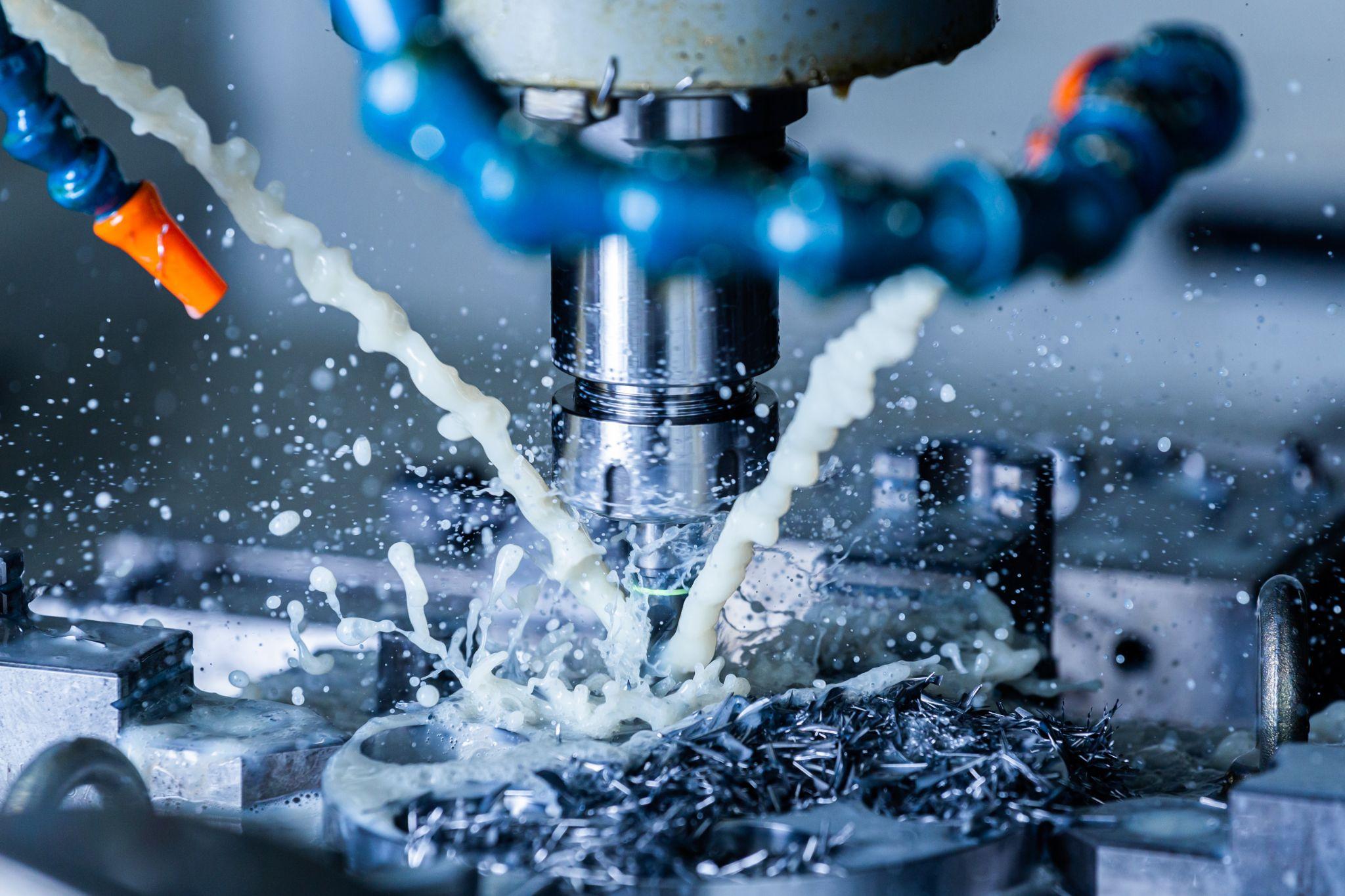
Because clamping devices are constantly exposed to cutting fluid and chips, regular cleaning and lubrication are necessary. Debris and chips easily adhere to moving parts and threaded sections, and if left unattended, they can prevent proper tightening. At the end of a shift, clean thoroughly with air blow and wipes, and apply grease as needed. Be sure to perform periodic inspections as well.
Check for loose bolts or nuts, worn clamp jaws, deterioration of hydraulic seals, air leaks, and more. If abnormalities are found, replace or repair promptly.
In particular, for hydraulic and pneumatic clamps, confirm that specified pressure is maintained; for magnetic clamps, check for reduced magnetic force and surface damage. It is important to perform method-specific inspection items at the manufacturer’s recommended frequency.
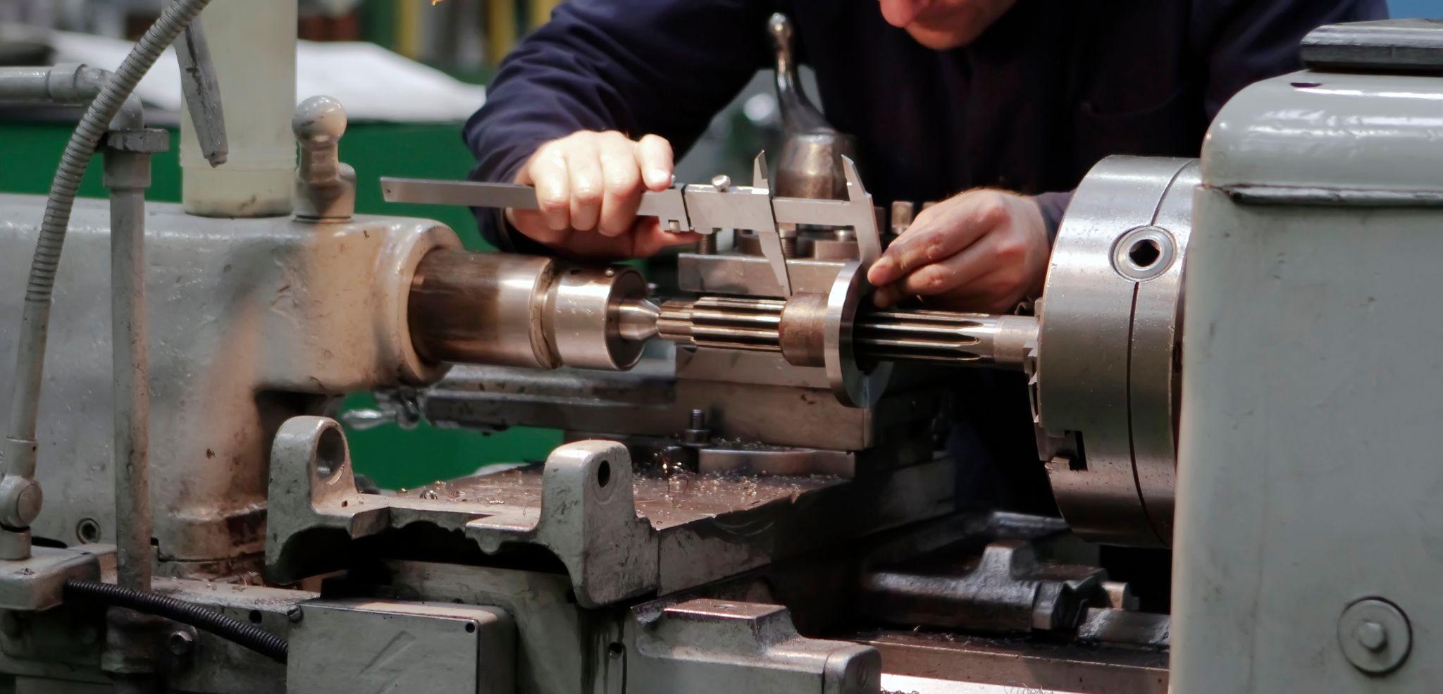
Verifying Clamping Force and Positioning Accuracy
Periodically verifying that the clamp delivers the intended force and accuracy also helps prevent problems. For example, managing tightening torque with a torque wrench or monitoring hydraulic clamp pressure with a gauge is effective.
For repeatability of locating, check after fixture changes for any positional shift using gauges or machined dimensions. Since long-used clamps can lose accuracy, maintaining precision through periodic calibration and parts replacement is necessary.
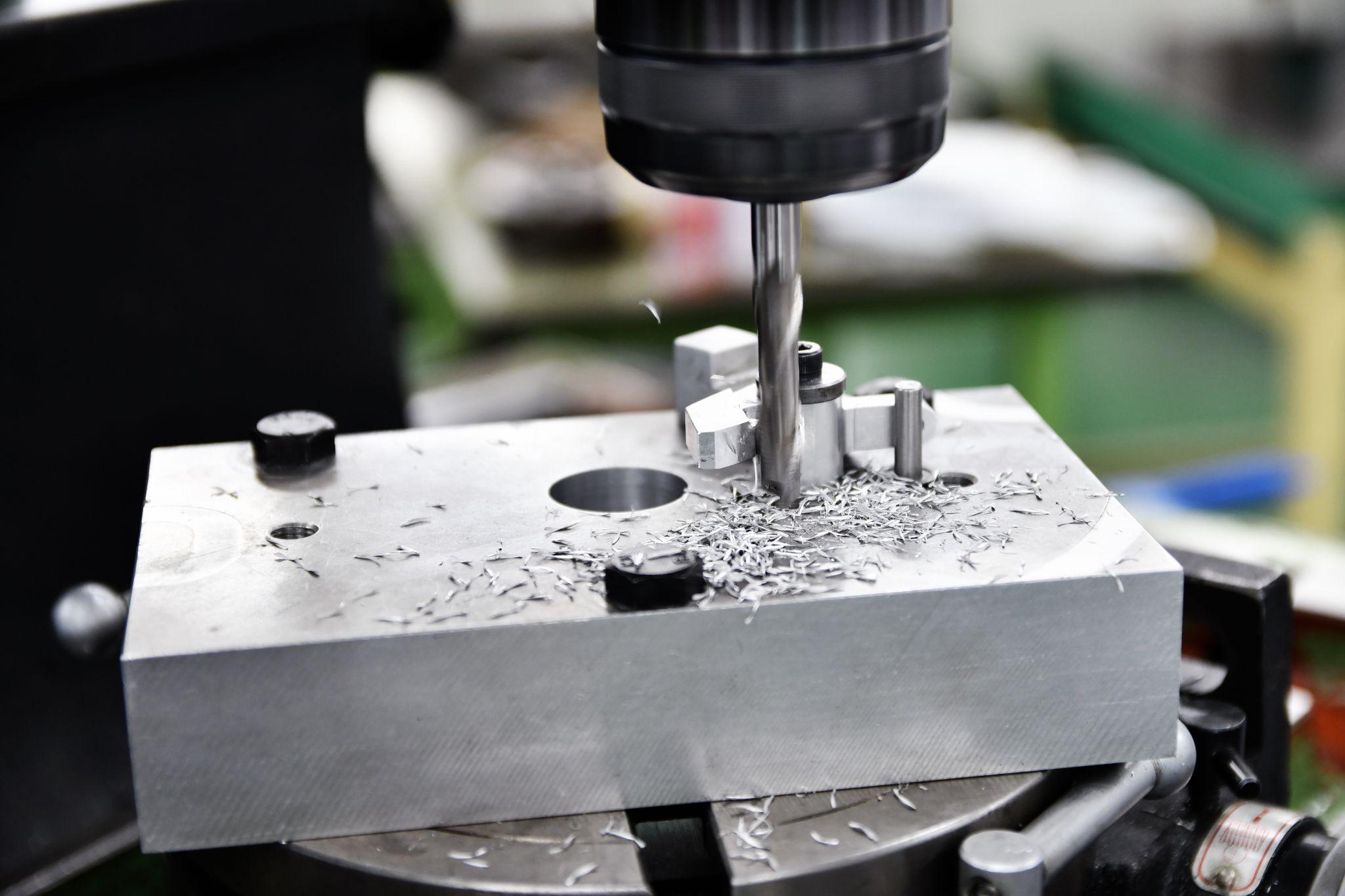
Removing Chips and Foreign Matter
A surprising pitfall is chips getting trapped. If chips or foreign matter get caught on clamping surfaces or locating pins, the workpiece may lift even if you believe it is tightened securely—leading to machining defects or workpiece ejection.
To prevent this, it is important to evacuate chips appropriately with air blow or coolant during machining and avoid accumulation in the clamping area. Especially during unmanned operation, incorporate in-machine cleaning into the program so the clamp remains clear at all times.
Because even small contamination can lead to serious accidents, don’t dismiss it as “just chips”—remove them thoroughly.
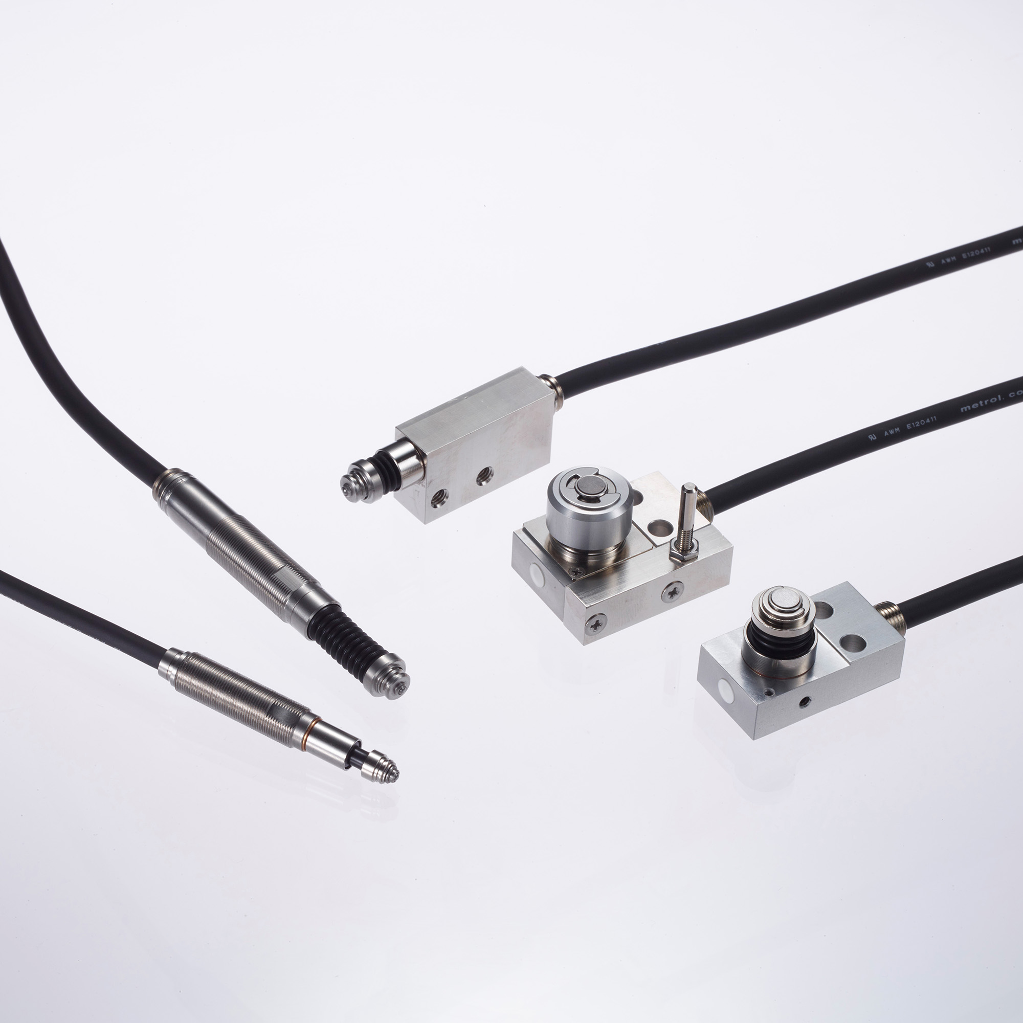
What Are Metrol’s High-Precision Positioning Sensors?
Reliable fixation by workholding clamps is a prerequisite for machining, but achieving even higher accuracy requires precise positioning at the micrometer level.
Metrol’s high-precision positioning sensors support precision machining by working together with these clamping systems, providing ultra-precise detection with 0.5 μm repeatability.
High-Precision Positioning Touch Switches
These are contact-type high-precision switches used for positioning and workpiece presence detection in machine tools, robots, and jigs. They achieve an extremely high repeatability of up to 0.5 µm and feature IP67-rated waterproof and dustproof protection, ensuring stable operation even in harsh environments. With more than 200 standard models available, they offer a wide range of variations, including designs for confined spaces, high-temperature environments, vacuum applications, and low contact force requirements.
Tool Setter (Tool Length Measurement Sensor)
This is a contact-type sensor installed on CNC machine tools and industrial robots for tool length measurement, reference position setting, and tool breakage detection. By automatically measuring and compensating for tool length, wear, and thermal displacement inside the machine, it helps prevent machining defects and significantly reduces setup time. It is one of Metrol’s best-selling products, with a proven track record of more than 500,000 units shipped in 74 countries worldwide.
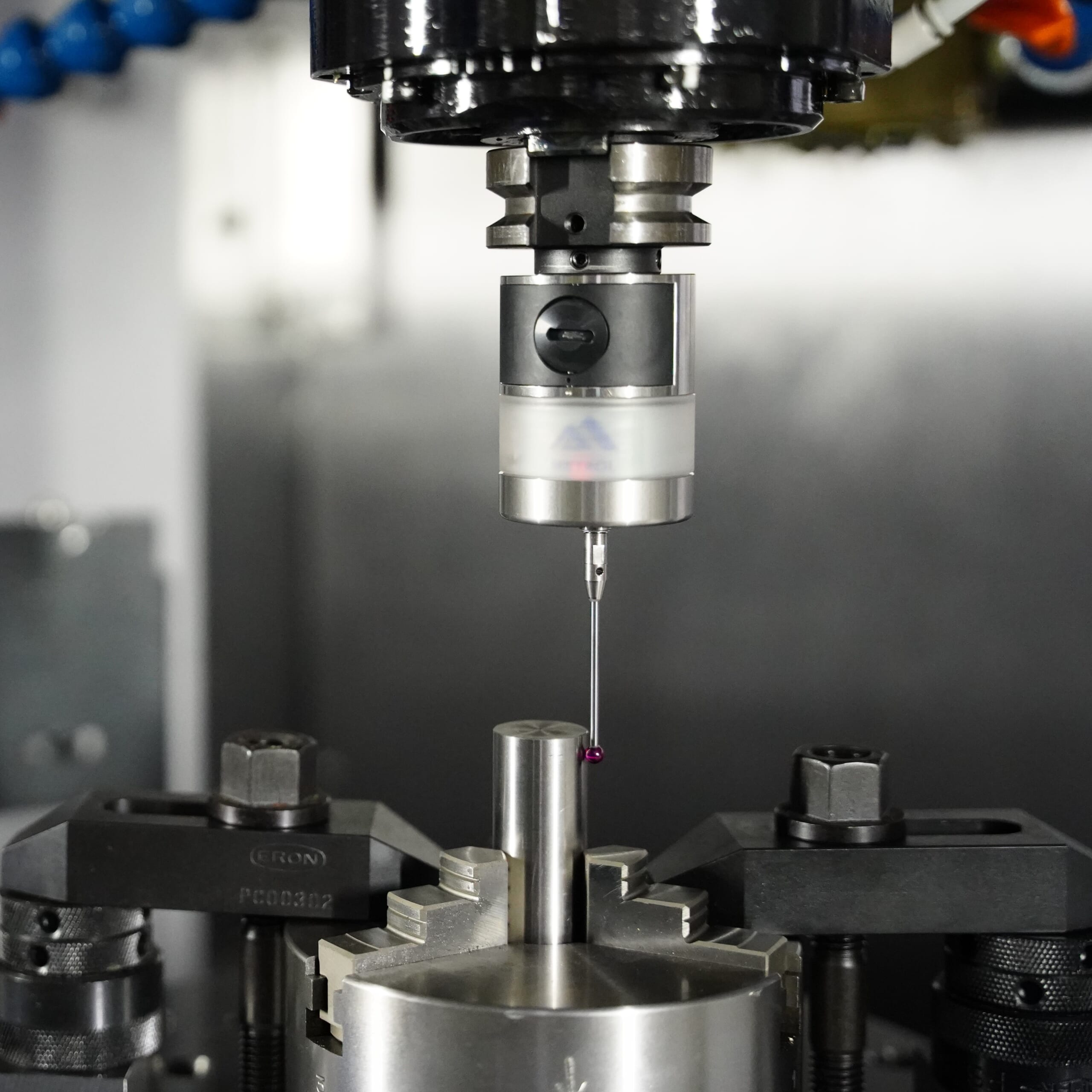
Touch Probe (On-Machine Measurement Probe)
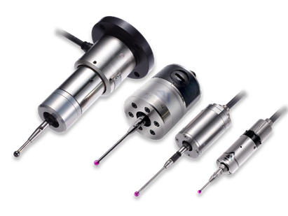
This is a contact-type probe for in-machine measurement, installed on machine tools and robots to automatically perform workpiece positioning (centering) before machining and dimensional measurement after machining. With a repeatability of 1 µm, it automates workpiece referencing and dimensional inspection, replacing skilled manual operations to reduce setup time and help prevent machining defects. Both wired and wireless models are available, meeting retrofit needs for 5-axis machining centers and robotic applications.
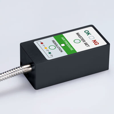
Air Gap Sensor (Pneumatic Sensor)
This is a non-contact sensor that uses air pressure to detect workpiece seating conditions with micron-level accuracy. It can detect gaps (“lift”) of less than 10 µm—previously difficult to measure—with a repeatability of ±0.5 µm, helping prevent machining defects and equipment downtime caused by insufficient contact between the workpiece and fixture. The sensor is used in applications such as semiconductor manufacturing processes, precision part clamping operations, and grinding wheel positioning on grinding machines, and it is a smart sensor that also supports the international standard IO-Link communication.