What Are Locating Pins? Types, Selection Criteria, and Practical Shop-Floor Insights
Locating pins are components used to locate (align) machine parts, ensuring accurate positional relationships when assembling parts together.
This article explains the types of locating pins, key points for selection, and common issues and how to address them.
Table of Contents
What Is a Locating Pin?
A locating pin is a component used on a jig/fixture to accurately locate a workpiece (part or material) and hold it stably in position.
It is a cylindrical pin inserted into holes or grooves in the workpiece during fixturing or assembly to align position, and it can be used either alone or in combination with a bushing (sleeve).
Roles of Locating Pins
Locating pins serve the following roles:
- Accurate Location and Secure Holding
By placing the workpiece precisely at a defined position and holding it stably, locating pins prevent positional shift during machining and assembly.
With a combination of high-precision locating pins and precisely finished holes, repeatability on the order of microns can also be achieved.
- Improved Quality and Repeatability in Machining and Assembly
By fixing the workpiece in the same position every time, consistency in machining is ensured. Variation in product quality is reduced, enabling high machining accuracy and repeatable assembly on the shop floor.
When inserted into the workpiece hole, a locating pin guides the workpiece into position and holds it reliably at the intended location.
This reduces misalignment and errors during machining and assembly, helping stabilize product quality.
Why Are Locating Pins Important?
In addition to improving machining accuracy, locating pins also help reduce setup time and improve operator safety. Their importance can be summarized as follows:
Improved Machining Accuracy and Consistency
As noted above, the main reason to use locating pins is to increase repeatability in machining and assembly and reduce variation. Because the workpiece can be set at a fixed position each time, human alignment mistakes decrease, helping prevent defects and rework.
Process Stability and Efficiency
Because locating pins enable quick and reliable location of a workpiece, they also reduce setup time and improve throughput.
Operators no longer need to align by eye; the pin-and-hole guidance allows the workpiece to be set in the correct position semi-automatically, improving efficiency and reducing human error.
In addition, secure pin-based location helps prevent shifts caused by vibration or cutting forces during machining, enabling a stable machining process.
Contribution to Safety
Fixtures that use locating pins also bring safety benefits for operators.
When the workpiece is securely fixed and supported, the risk of unexpected movement or detachment during machining is reduced.
For example, if a workpiece shifts while machining with a high-speed rotating tool, it may lead to tool breakage or accidents caused by the workpiece being thrown.
A fixture that is properly located and secured with locating pins holds the part while guiding the tool’s path, preventing movement or drop-off during machining and reducing the risk of accidents and injuries.
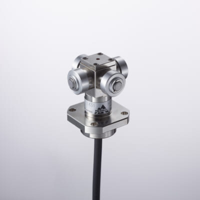
High Precision Positioning
- MT-Touch Switches-
0.5 μm repeatability without amplifier IP67, highly resistant to adverse environments
Click here ›Types of Locating Pins
Locating pins come in various types and shapes depending on the application. Common types and their characteristics are as follows:
Straight Pins
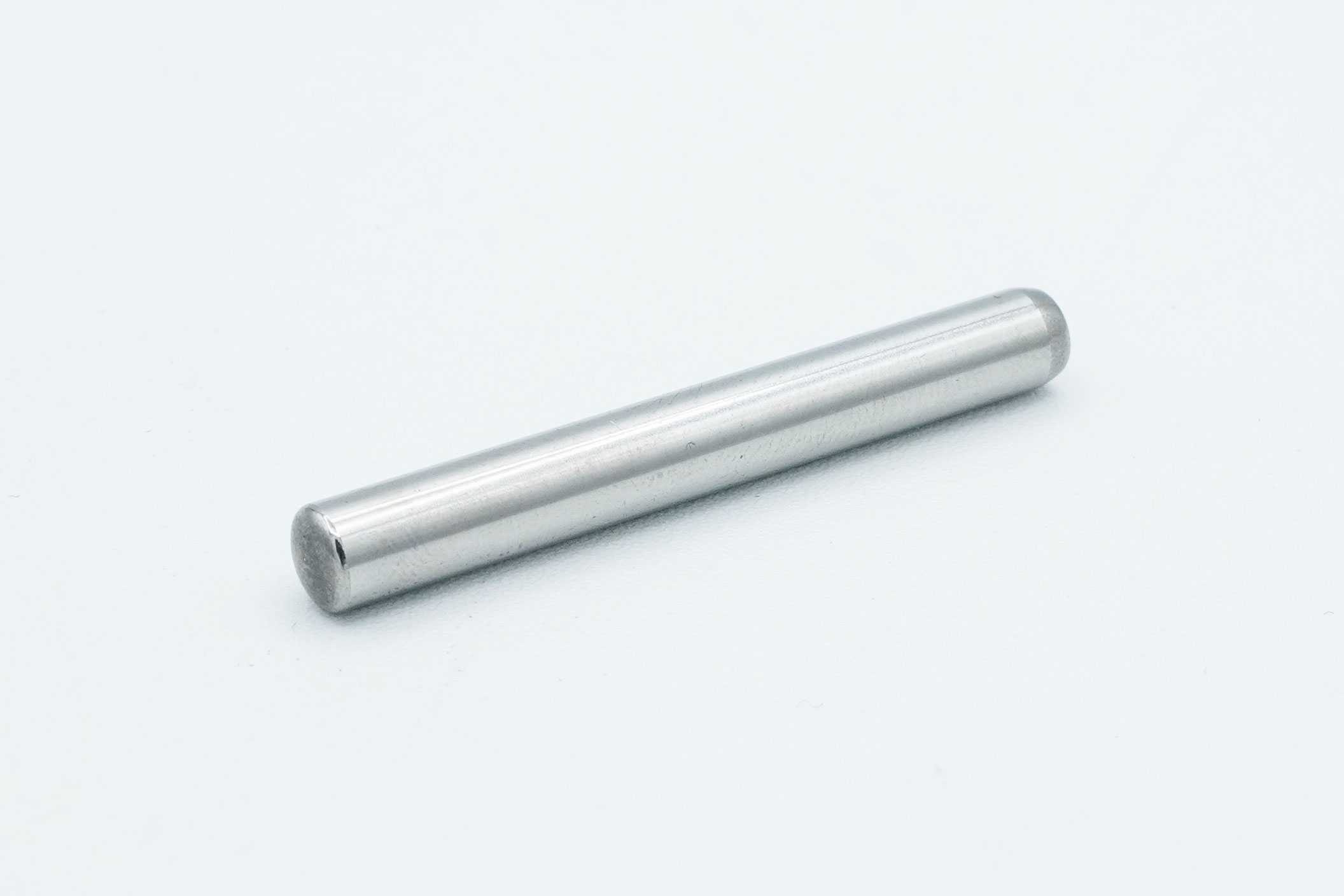
This is the most basic type of locating pin—a straight cylindrical pin. Its simple structure makes it versatile, and it is often used for location where ultra-high precision is not required or under light loads.
In many cases, it is press-fit directly into the fixture and used as a “temporary holding” solution in short- to mid-volume production fixtures.
While the structure is simple, repeated insertion/removal causes wear, and replacement can be difficult if loosening occurs after long-term use (due to the press-fit). Therefore, it is best suited to applications where pin replacement is not expected.
Taper Pins
A taper pin has a slightly tapered shape along its axis. Because its diameter changes over the full length, driving it into a matching tapered hole (press-fitting) creates a tight, gap-free fit for strong retention.
For example, inserting a taper pin into precision matched holes and tapping it in with a hammer can correct slight hole misalignment while ensuring accurate location.
Once installed, it is highly resistant to shifting and loosening, so it is used in applications requiring high shear strength and positional repeatability—such as machine tool components and die/mold location.
Many types have threads on the small end for removal, allowing the pin to be pulled out easily by engaging a tool with the threads.
Shoulder Pins (Stepped Pins)
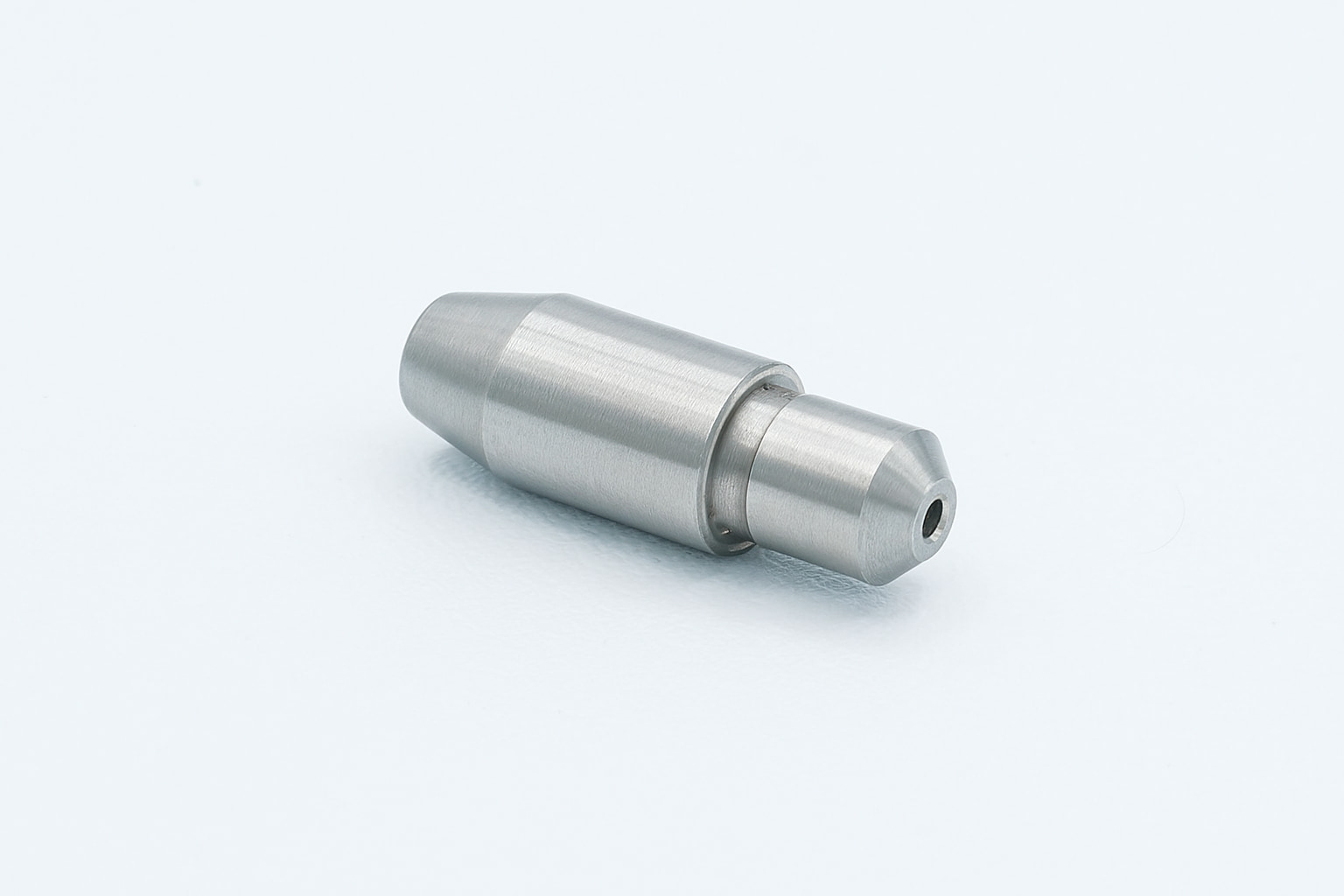
This type has a step (shoulder) on the pin body, where the shoulder contacts a datum surface of the workpiece or part to act as a stop.
For example, when inserted into a hole, the shoulder stops at a defined depth, preventing the pin from being inserted too far or passing through excessively.
Because the shoulder can bear load, it is also suitable for supporting heavy workpieces.
Although more complex than a standard straight pin, a shoulder pin combines locating and supporting functions, making it well-suited for locating heavy items and maintaining accuracy.
Spherical-Tip Pins
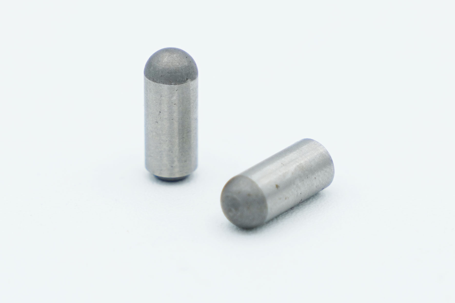
This locating pin has a spherical or rounded tip.
The rounded tip smoothly guides insertion, making engagement easier even if the hole position or angle is slightly off.
In particular, even if the hole axis is not perfectly perpendicular to the pin axis or the insertion direction is slightly angled, the spherical geometry reduces the chance of catching on the hole edge or galling/jamming.
For this reason, it is suitable for applications with frequent insertion/removal and fixtures where operators need to set workpieces quickly by hand.
Diamond Pins
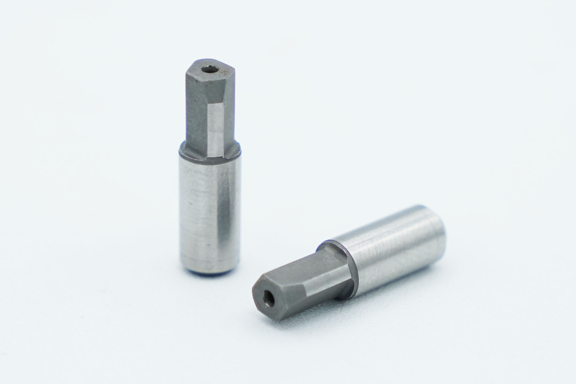
A diamond pin is a special locating pin with a diamond-shaped tip (also called a diamond dowel). With four flat faces at the tip, it is designed to contact and locate in only a specific direction (axis).
On its own, it can be inserted into a hole like a standard round pin, but it shows its true value when used in combination with a round pin.
In fixture design, a round locating pin is placed in one hole to constrain position in both X and Y directions, while a diamond pin is placed in another hole to constrain only the remaining direction (e.g., rotation), leaving one axis with clearance.
This prevents “over-constraint” issues that often occur with two round pins, such as poor fit due to miscentering or interference.
Spring Pins
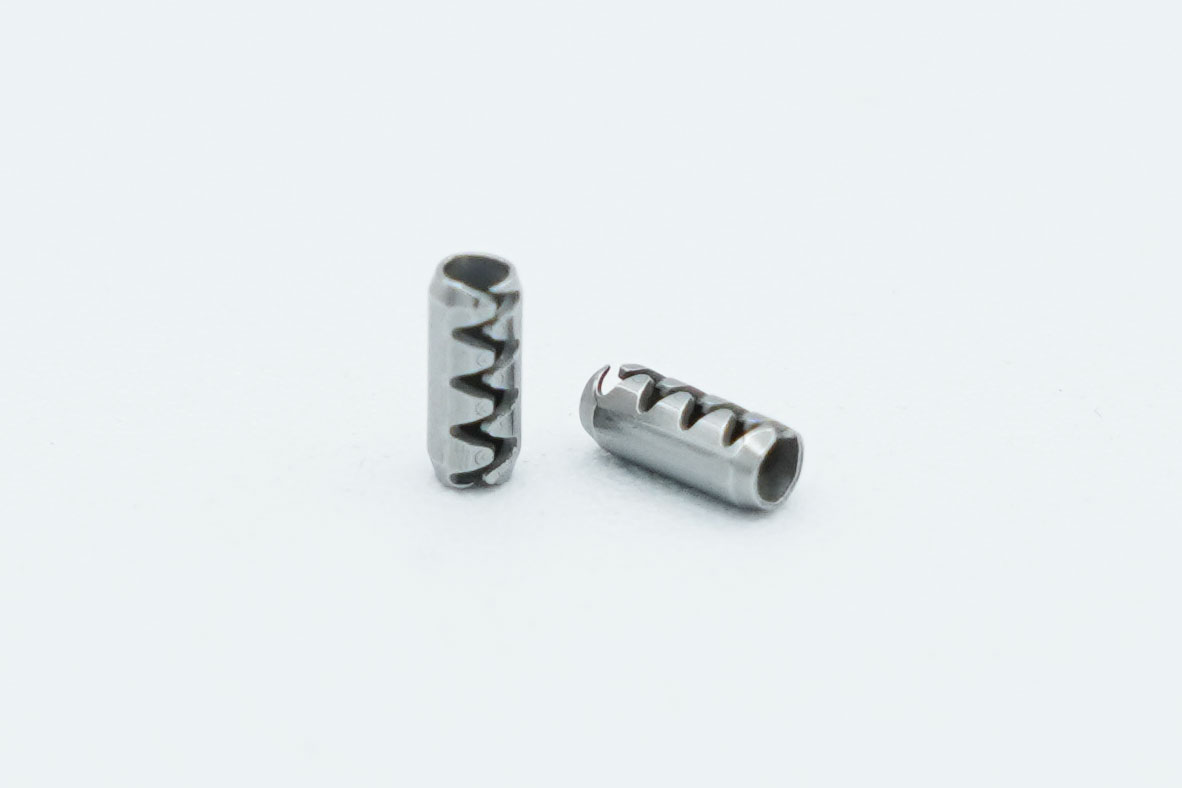
A spring pin is a hollow, elastic pin made of spring steel, also called a split pin.
Because the pin can elastically compress in the radial direction like a spring, inserting it into a hole applies tension against the hole wall, providing self-retention.
This self-retaining force makes it resistant to loosening even under vibration, so it is also used as a fastening or joining pin.
For locating applications, it cannot deliver the same high precision as spherical-tip or taper pins, but it is easy to install/replace and low cost, so it is used for temporary location or assembly assistance.
For example, it is commonly used as a combined locating/connecting pin to temporarily align two parts via their holes, followed by final tightening with bolts.
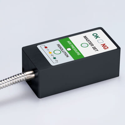
High-precision seating confirmation of workpiece and jig
- Air Gap Sensor -
You can check not only "presence/absence" but also "adhesion (gap)" at the same time with a repeatability of ±0.5 μm.
Click here ›Selection and Design of Locating Pins
When selecting and designing locating pins, it is necessary to consider various factors depending on the application.
Locating Tolerances and Clearance
Setting dimensional tolerances for the pin and the mating hole determines the balance between locating accuracy and workability.
In general, one reference pin uses a precision fit with minimal clearance to the hole (for example, a g6-class pin in an H7 hole), while the other pin (such as a diamond pin or floating pin) is given clearance in one direction.
This enables high-accuracy location while avoiding over-constraint by the two pins.
It is also important to improve usability depending on the setup method—for manual fixtures, increase the lead-in (use a larger tip taper angle) to make loading easier; for heavy workpieces or automated loading, provide an appropriate clearance so insertion remains smooth even with tight tolerances.
For example, when locating a workpiece in an automated machine, a relatively shallow taper angle of about 10–30 degrees at the pin tip increases the guiding effect, and the pin-to-hole clearance is set slightly larger to prevent interference due to miscentering.
On the other hand, when placing a light workpiece by hand onto a fixture, a sharper lead of around 60 degrees can help achieve quick location—tolerance design should be tailored to the situation.
Materials and Heat Treatment
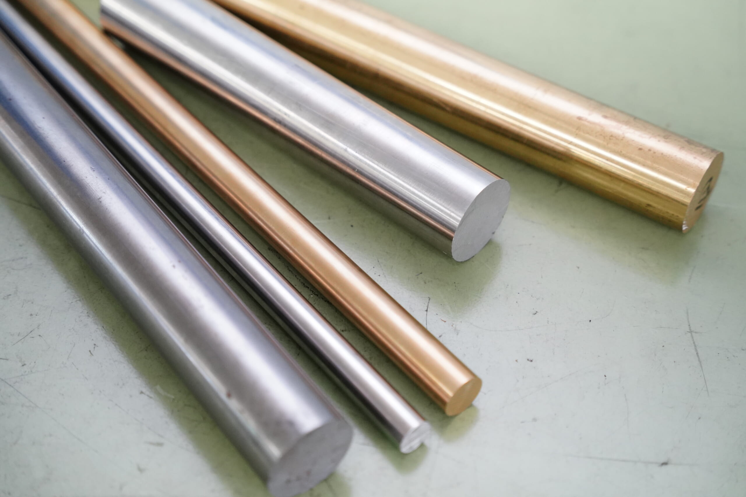
Because of their role, locating pins are often made from materials with excellent hardness and toughness.
Typically, hardened and ground tool steels or alloy steels are used. While they offer high hardness and wear resistance, they also tend to be more brittle than untreated steels.
In environments requiring corrosion resistance (for example, fixtures that go through washing processes or outdoor use), stainless steel pins are used. Stainless steel is rust-resistant and strong, though more expensive, and is selected to maintain line cleanliness and reduce maintenance frequency.
In applications with light loads and frequent replacement, aluminum or brass pins may also be used. Aluminum is lightweight, easy to machine, and oxidation-resistant, but not suitable for heavy loads; brass offers good corrosion resistance and moderate strength, but tends to soften at elevated temperatures.
In any case, it is important to select materials suitable for the operating environment and required service life, and apply heat treatment as needed (hardening/tempering, etc.) to improve resistance to wear and deformation.
Ease of Removal and Safety Measures
Designing for smooth maintenance and reset work for locating pins is also important.
When using press-fit pins, providing a pin removal hole (a hole that allows the pin to be driven out with a punch from the opposite side) makes replacement easier.
Commercial pull-out pins with internal threads (tapped holes) are also available, allowing safe removal using a threaded slide hammer or similar tool.
For removable pins, some designs include handles (L-shaped or T-shaped grips), enabling quick insertion/removal without tools.
Such design considerations—preventing pins from falling out or being lost while ensuring reliable removal when needed—lead to safer work and improved maintainability.
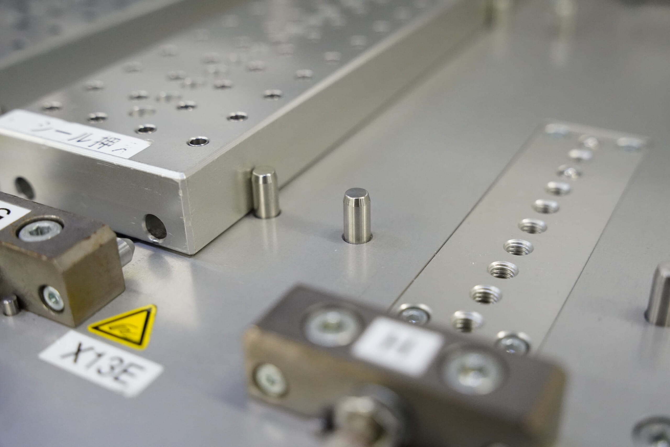
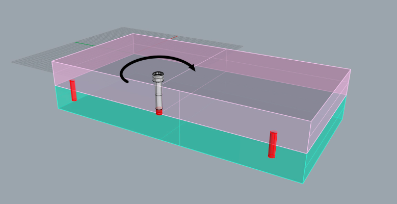
Design Considerations for Machining Fixtures Using Locating Pins
By using dedicated fixtures with locating pins for mass production or special-shape machining, even less-experienced operators can perform high-accuracy, high-quality machining, and more workplaces are minimizing reliance on specific individuals for certain tasks.
For aligning complex shapes and machining products requiring high dimensional accuracy, using fixtures with locating pins often greatly improves workability compared with using a vise, enabling labor savings and shorter machining time.
When designing a fixture, it is important to determine pin positions so the workpiece can be mounted safely and accurately, and also to design the pin protrusion length so it does not interfere with machining areas or tools.
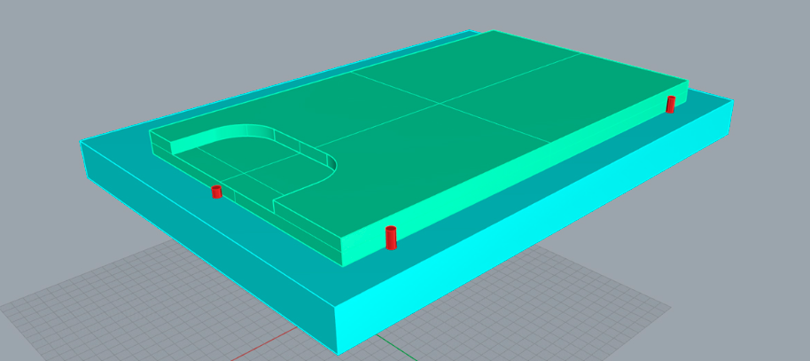
When machining a step like the one on the left side of the figure above, one option is to reduce the pin protrusion length so the pin does not interfere with the machining area.
Another approach is to place the pin farther from the machining area, but it may interfere with clamp screw holes, and reduced rigidity due to clamp positioning could cause chatter on the machined surface.
By changing the pin protrusion length as shown above, it becomes possible to clamp the workpiece corner, which should also stabilize workpiece mounting.
Tool Wear & Thermal Compensation
- Tool Setter -
Performs wear, chipping, and thermal displacement compensation, contributing to maintaining the constant machining precision of the machine tool
Click here ›Shop-Floor Perspectives: Practical Points for Designing and Using Locating Pins
Here are three key points about locating pins from a shop-floor perspective.
How to Improve the Machining Accuracy of Pin Holes
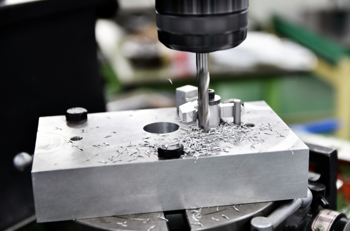
When machining holes for locating pins, not only hole diameter accuracy but also hole position accuracy becomes important.
In recent years, it has become common to machine locating-pin holes using CNC equipment such as machining centers; however, the simple sequence of centering → pilot drilling → chamfering → reaming does not yield the intended positional accuracy.
Therefore, the process is centering → pilot drilling → end milling → chamfering → reaming, but slight positional deviations can occur due to machine aging and other factors.
On newer machines, preload is applied between the ball screw and ball nut, resulting in designs with little backlash; however, using functions such as backlash compensation can also be effective in minimizing positional deviation.
If backlash compensation cannot be used for some reason, establishing rules such as “always machine from right to left and from back to front” and keeping the ball-screw drive direction consistent can help suppress backlash-induced positional shift and hole-pitch errors as much as possible.
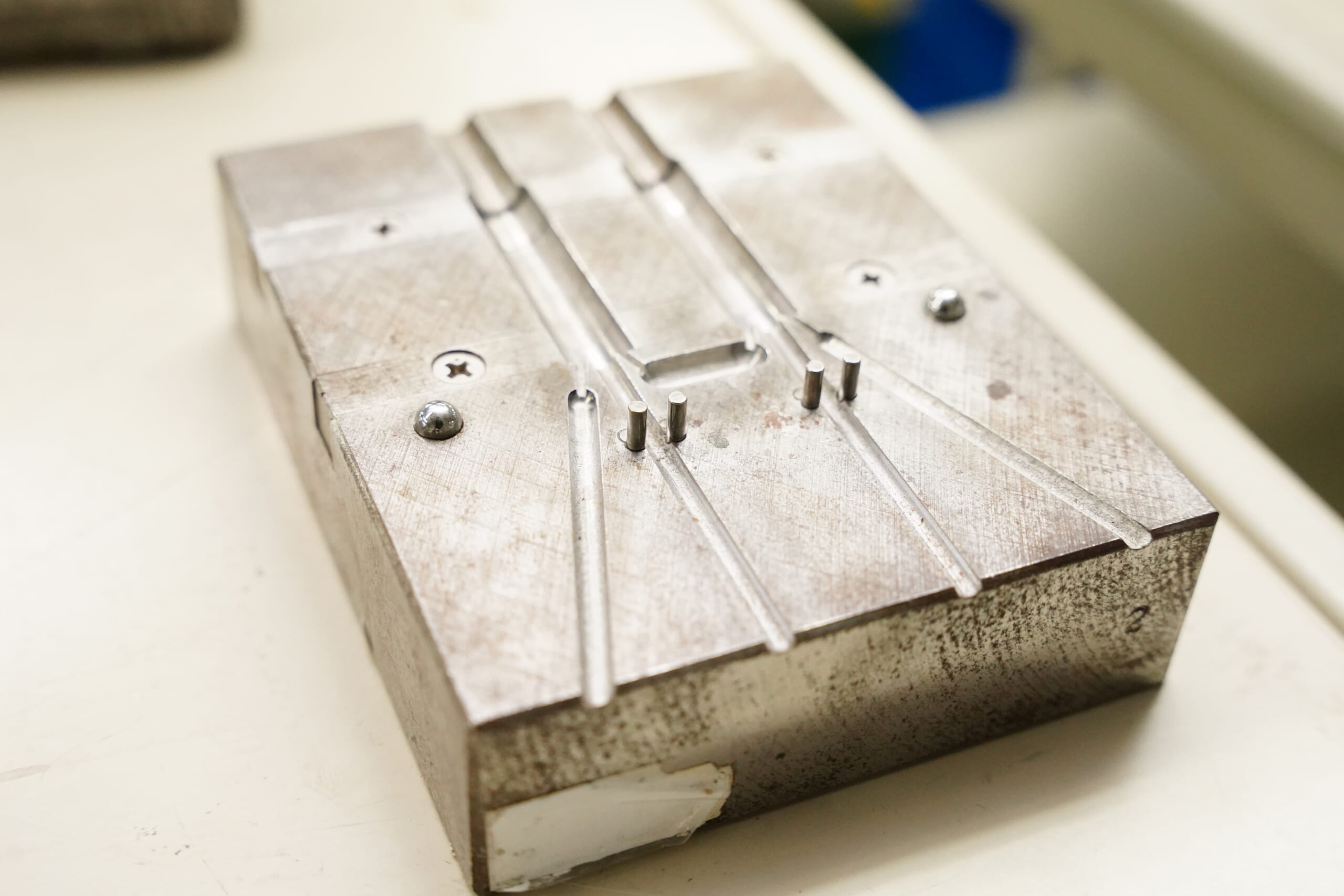
For Large Components, Consider Disassembly Workability and Safety
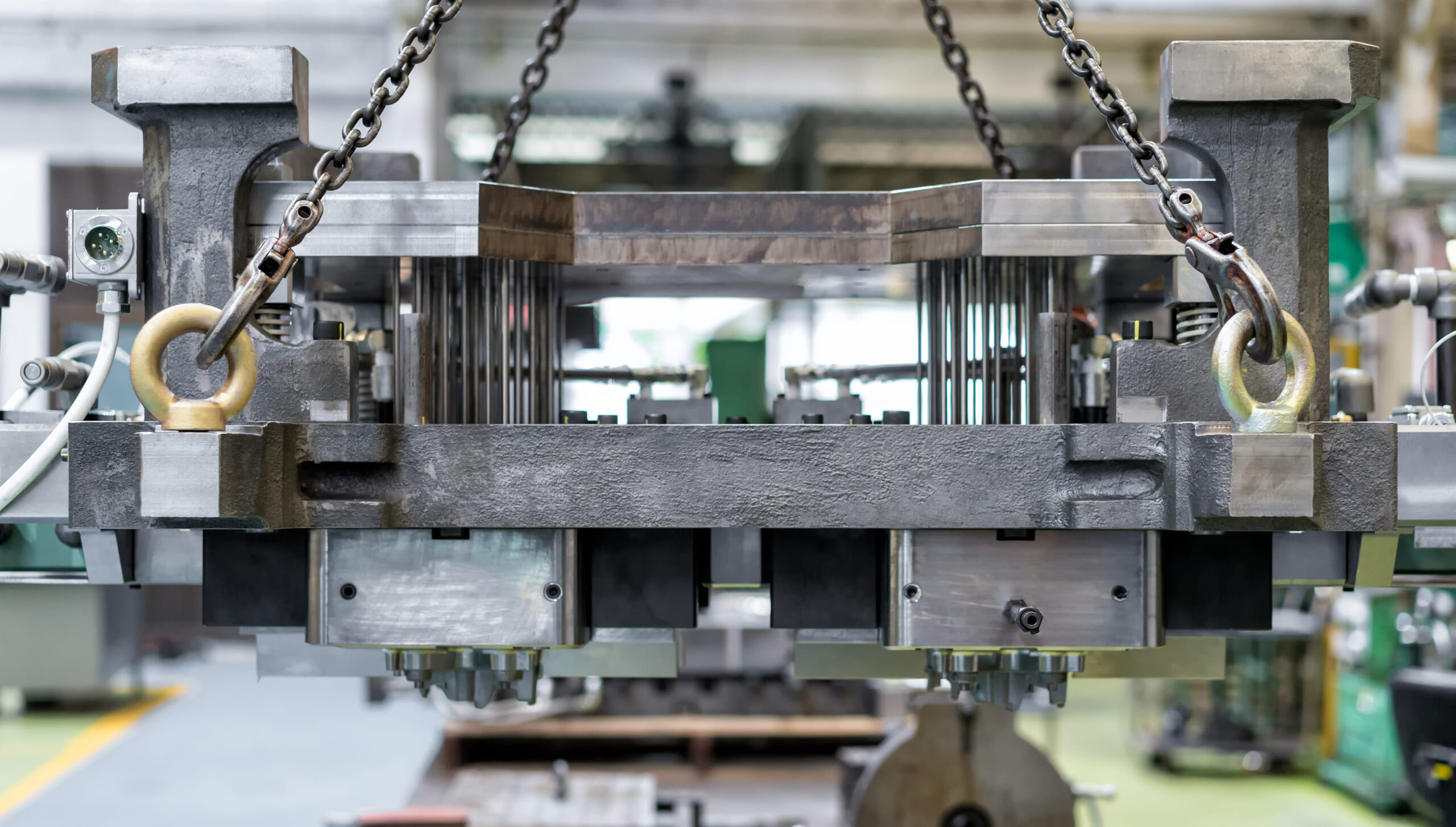
When assembling large and heavy components, designing with disassembly and maintenance workability in mind improves operator safety and assembly repeatability.
For large components handled with cranes during assembly, it is also important to consider the placement of lifting bolts (such as eye bolts) based on weight balance, so locating pins and holes can be aligned easily.
If lifting positions (threaded holes) are determined with balance in mind during design, problems such as the product tilting during assembly and becoming “hard to align to the locating pins” can be eliminated, improving workability.
Assemblies that use locating pins are often difficult to disassemble during maintenance, and depending on the case, the cost and labor required can become significant.
As shown above, if threaded holes for disassembly are added during design and bolts are inserted into these holes to jack the parts apart when disassembly is needed, the parts can be separated more easily even if they are stuck due to oil or similar causes.
At this time, using bolts with resin or rubber cushioning on the tip can prevent damage to the surface that serves as the jacking base.
If that is difficult, place the jacking threaded holes in areas where scratches would not be an issue.
Precautions When Using Locating Pins in Angle Plate Fixtures
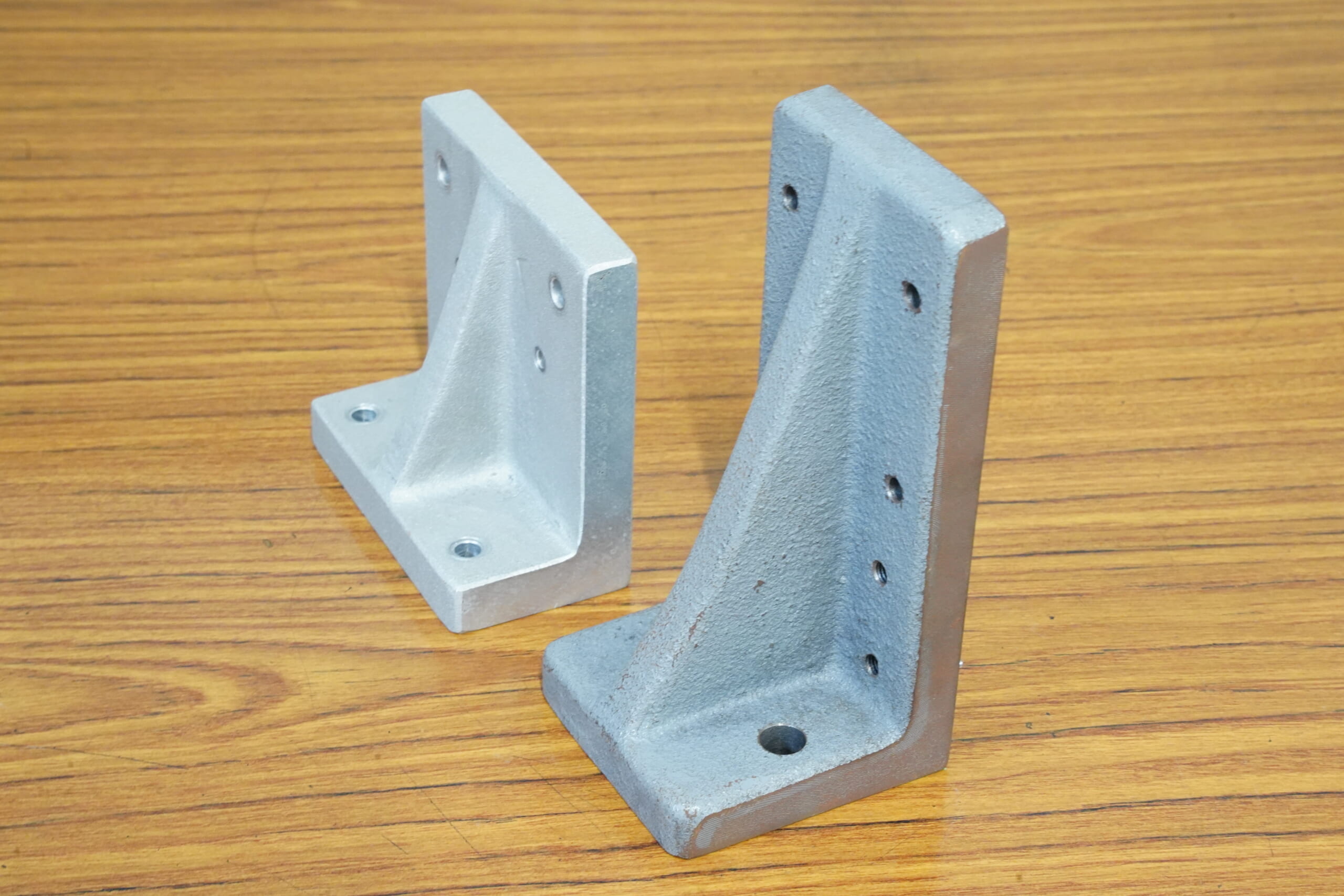
When using locating pins in angle plate fixtures (fixtures used to secure workpieces and maintain squareness) for horizontal or simultaneous 5-axis machining centers, use pins with pull-out threaded holes whenever possible.
Angle plates have substantial thickness and can become quite large depending on the machine size. Therefore, if the locating-pin hole is damaged and the angle plate itself becomes unusable, the resulting loss (cost and productivity impact) can be orders of magnitude larger.
To prevent damage to pin holes, ensure you can choose maintenance and replacement methods for locating pins that place as little load on the holes as possible.
Because angle plates are often machined after being mounted on the machine—achieving the required surface roughness, angles, and positional accuracy—it is recommended to enable locating pin replacement and maintenance without removing the angle plate from the machine as much as possible.
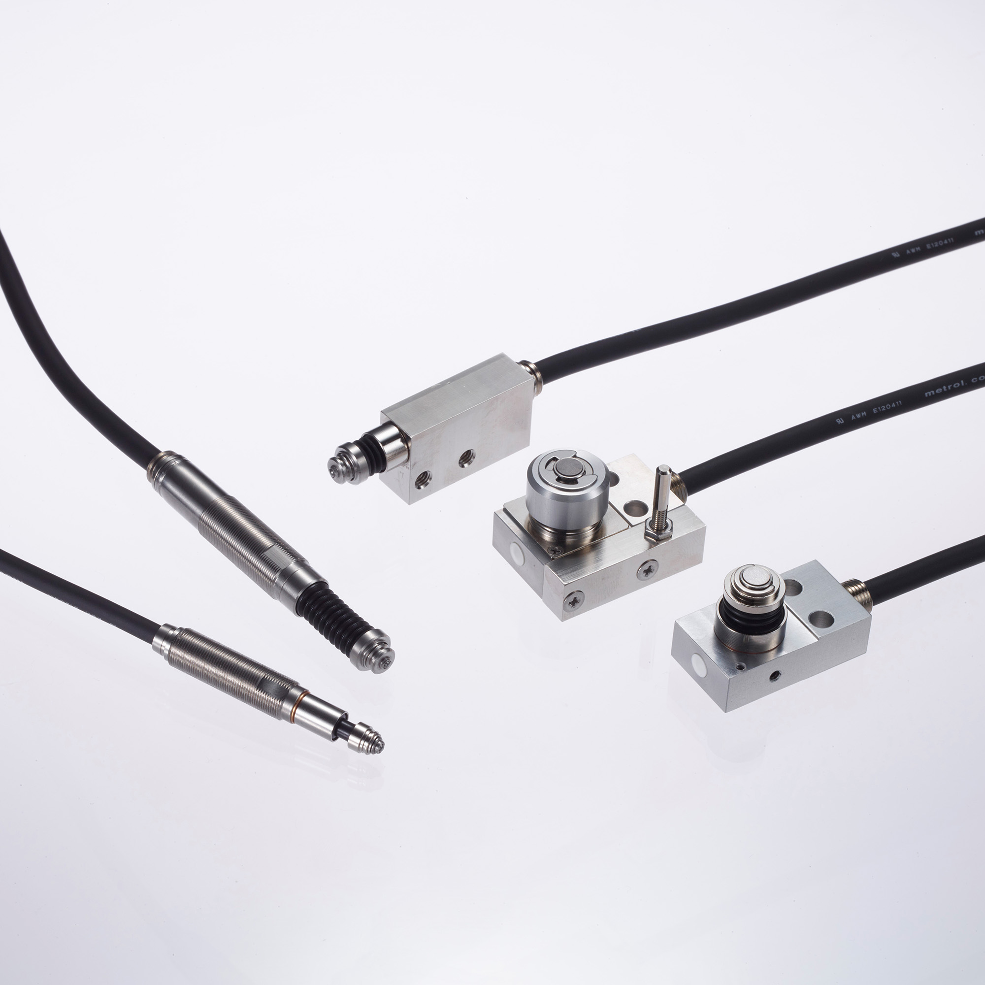
What Are Metrol’s High-Precision Positioning Sensors?
Locating pins are widely used as a fundamental method to match fixtures and workpieces, but loss of accuracy due to wear and the effort of replacement are difficult to avoid.
With Metrol’s positioning sensors, stable positioning can be achieved with high repeatability at the micron level.
High-Precision Positioning Touch Switches
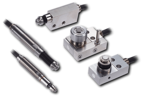
These are contact-type high-precision switches used for positioning and workpiece presence detection in machine tools, robots, and jigs. They achieve an extremely high repeatability of up to 0.5 µm and feature IP67-rated waterproof and dustproof protection, ensuring stable operation even in harsh environments. With more than 200 standard models available, they offer a wide range of variations, including designs for confined spaces, high-temperature environments, vacuum applications, and low contact force requirements.
Tool Setter (Tool Length Measurement Sensor)
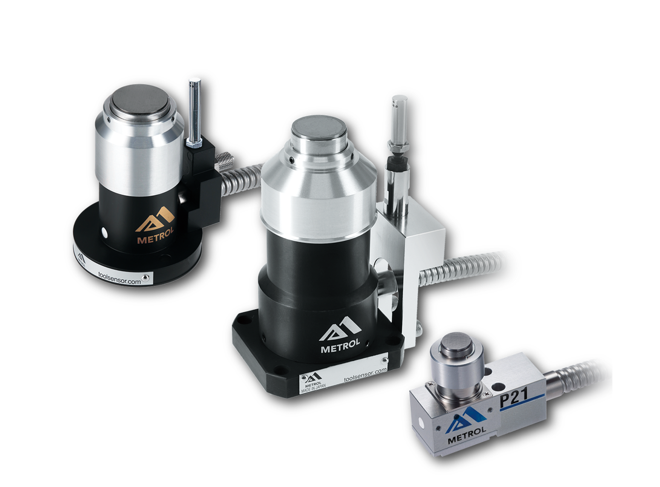
This is a contact-type sensor installed on CNC machine tools and industrial robots for tool length measurement, reference position setting, and tool breakage detection. By automatically measuring and compensating for tool length, wear, and thermal displacement inside the machine, it helps prevent machining defects and significantly reduces setup time. It is one of Metrol’s best-selling products, with a proven track record of more than 500,000 units shipped in 74 countries worldwide.
Touch Probe (On-Machine Measurement Probe)
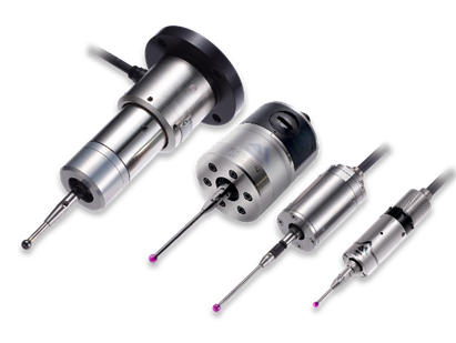
This is a contact-type probe for in-machine measurement, installed on machine tools and robots to automatically perform workpiece positioning (centering) before machining and dimensional measurement after machining. With a repeatability of 1 µm, it automates workpiece referencing and dimensional inspection, replacing skilled manual operations to reduce setup time and help prevent machining defects. Both wired and wireless models are available, meeting retrofit needs for 5-axis machining centers and robotic applications.
Air Gap Sensor (Pneumatic Sensor)
This is a non-contact sensor that uses air pressure to detect workpiece seating conditions with micron-level accuracy. It can detect gaps (“lift”) of less than 10 µm—previously difficult to measure—with a repeatability of ±0.5 µm, helping prevent machining defects and equipment downtime caused by insufficient contact between the workpiece and fixture. The sensor is used in applications such as semiconductor manufacturing processes, precision part clamping operations, and grinding wheel positioning on grinding machines, and it is a smart sensor that also supports the international standard IO-Link communication.