Stop Bolts 101: From Definition to Practical Applications
A stop bolt is a small threaded component that plays an essential role in positioning machine parts and controlling motion limits.
Despite its simple structure, it serves two key functions—“fixing” and “stopping”—across a wide range of applications such as production equipment, automobiles, and material-handling systems, supporting both machine accuracy and safety.
This article organizes the definition and roles of stop bolts, their main types and structures, and typical use cases, then explains key considerations for design/selection along with practical shop-floor advice.
It also covers advanced examples from real machining operations and compares stop bolts with the latest high-precision positioning sensors—providing a comprehensive set of points designers and engineers should understand.
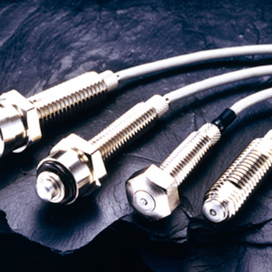
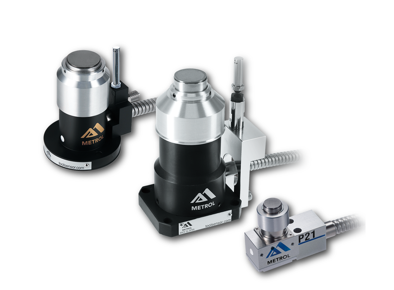
High Precision Positioning
- MT-Touch Switches-
0.5 μm repeatability without amplifier IP67, highly resistant to adverse environments
Click here ›Table of Contents
What Is a Stop Bolt? Definition and Roles
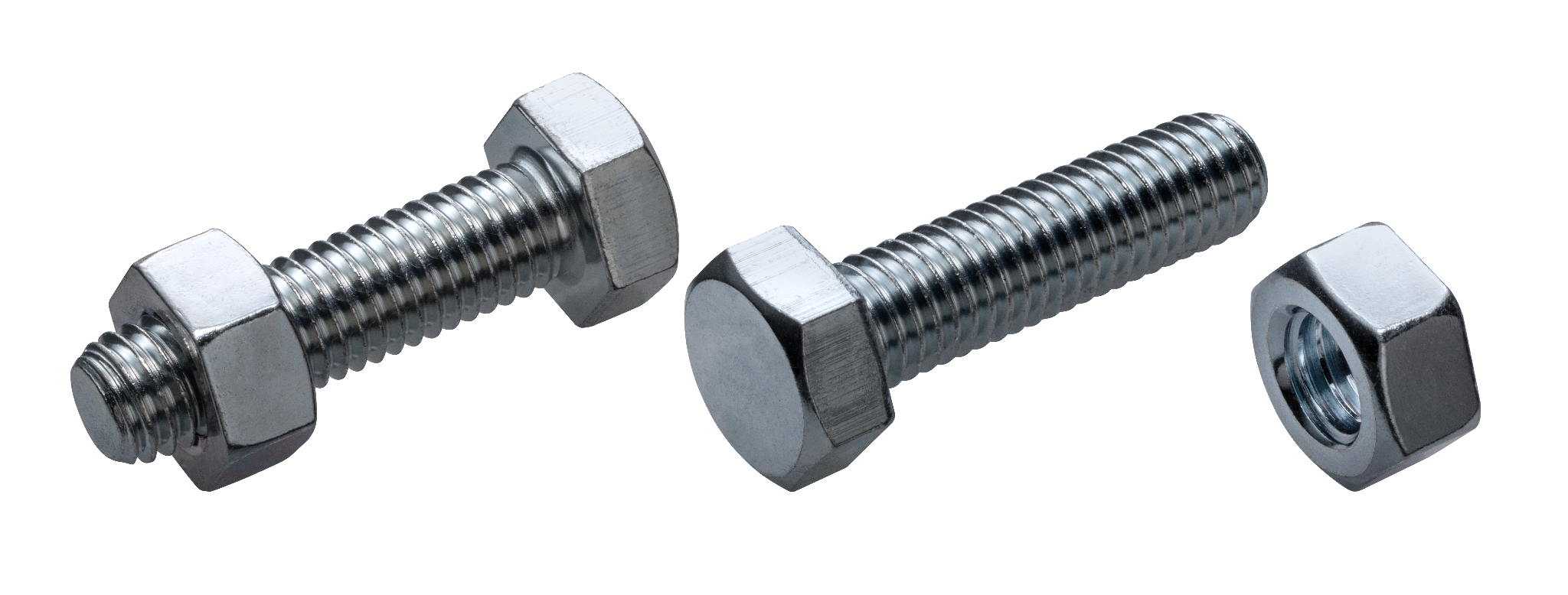
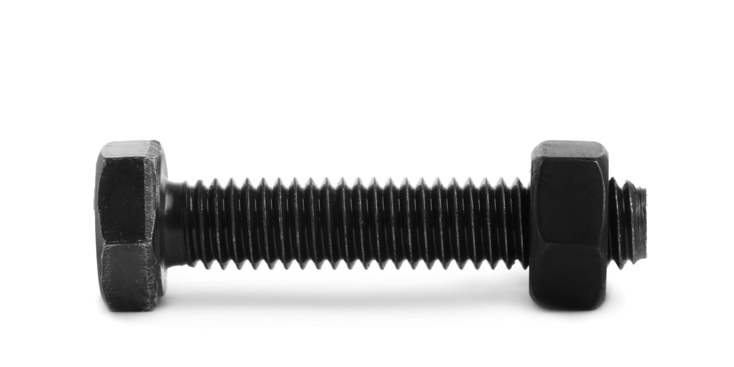
A stop bolt is a threaded component used to limit the movement of a moving part or to fix the relative position of components.
It is typically screwed directly into a machine component without a nut, and it fixes the target part by applying a clamping force at the tip.
For example, when preventing a pulley or gear mounted on a shaft from slipping, a headed bolt may interfere due to its protruding head; a headless stop bolt (set screw) sits flush with the surrounding surface and won’t hinder smooth operation.
Even in small sizes, stop bolts can provide sufficient holding force, functioning both as a fastener to secure a component at a specified position and as a mechanical stop.
Stop bolts serve two primary roles.
One is for fixing—used, for instance, to connect a shaft and hub—where the tip presses against the material to position and secure it through friction.
The other is as a stop (end stop), where the screw is set to contact a surface to adjust and limit the machine’s travel range.
In stop applications, either the bolt head or the screw tip contacts the moving part’s stop surface, halting motion at the required position.
After adjustment, the setting is often locked with a nut to prevent loosening, enabling precise positioning and reliable fixation.
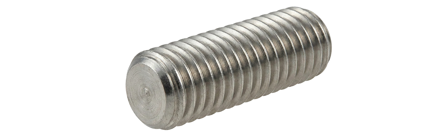
Main Types and Structures of Stop Bolts
The key differences in stop-bolt geometry are whether there is a head and what tip shape is used.
A typical headless type is the “hex socket set screw” (often called an imoneji in Japanese, or a grub screw), which sits entirely inside the part and leaves a smooth outer surface.
There are also headed stop bolts, where the head is used as the contact face—often as an adjustment screw or a fixing bolt.
Using the head of a hex bolt as the stop provides a broad contact surface, enabling stable positioning.
Several tip shapes are available depending on the application. JIS standards define types such as flat point, cone point, cup point, dog point, and oval point. The main characteristics are as follows.
Flat Point
The tip is flat with a large contact area, making it less likely to damage the mating part.
It is suitable for applications requiring repeated positioning adjustments and can be used on thin-walled parts or softer materials.
Because the frictional resistance to rotation is relatively low, it is not ideal for high axial holding force, but it works well for fine adjustment.
Cup Point
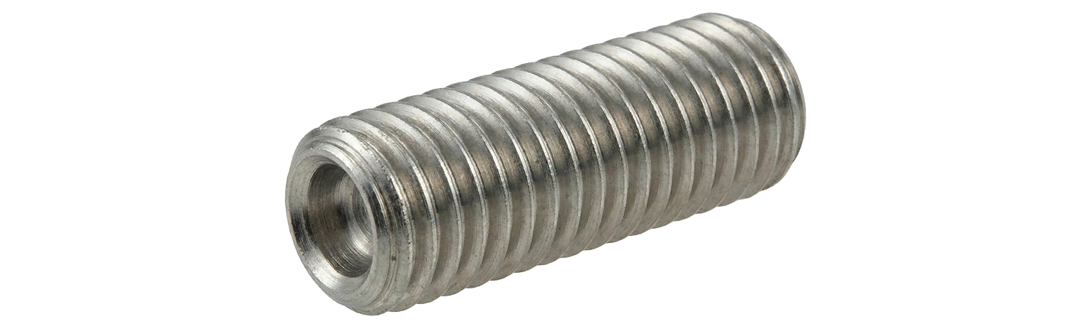
The tip is concave like a cup, and a thin edge around the contact area grips the surface.
When tightened, the edge bites into the mating part, providing strong friction and appropriate contact pressure to secure it. It resists loosening under vibration and is the most widely used standard tip shape in general machinery.
However, it may leave a circular indentation on the mating part.
Cone Point
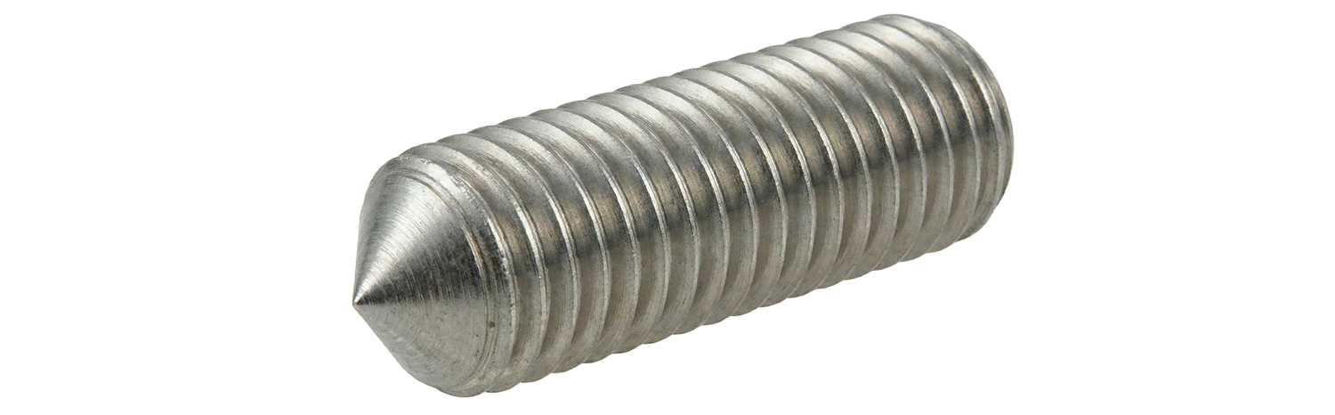
This type has a sharp conical tip.
Because it penetrates deeply into the mating surface, it provides the highest holding power (friction resistance) among the tip types. It is effective when you need strong fixation on softer materials and is suitable for semi-permanent positioning.
However, because the load is concentrated at a single point, it tends to leave marks and is not suitable for frequent repositioning.
Dog Point
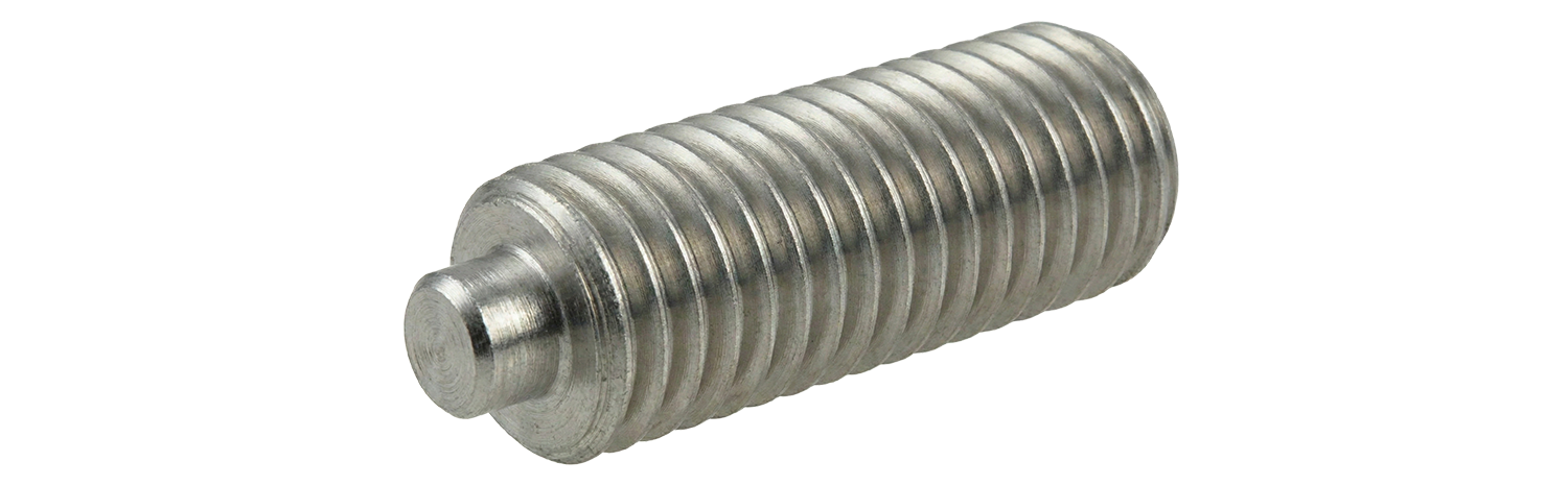
This tip has a cylindrical projection (dog point) with a flat end.
By preparing a hole or recess in the mating part and inserting the projection into it, you can achieve reliable positioning. It is useful for equipment that is repeatedly disassembled and reassembled and is effective as an anti-shift feature to ensure the same position every time.
A “half dog point” has a shorter projection and is used with shallower holes.
Oval Point
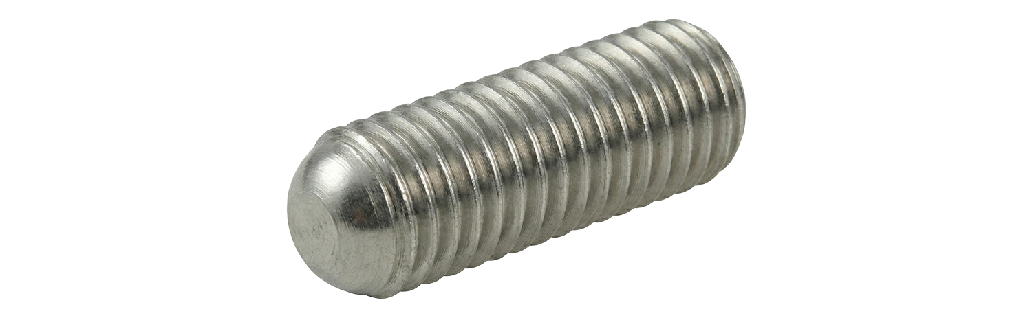
The tip has a gently rounded shape.
Although the contact point is small and the local pressure is high, it minimizes damage to the mating surface.
It is effective when slight position adjustment is needed without fully loosening the screw and is used where the position is changed periodically.
Nylon-Tipped
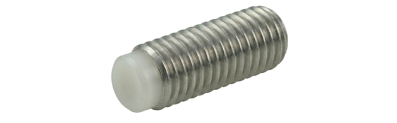
This is a special type with a soft tip material such as resin (nylon) or brass.
Even on curved or rough surfaces, the soft tip deforms appropriately to grip without damaging the surface. It is used in precision equipment, on finished surfaces you don’t want to mar, or in locations where vibration loosening is a concern to gain an anti-loosening effect.
Knurled Cup Point
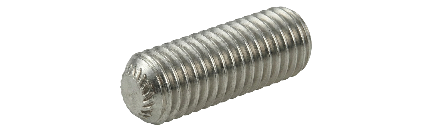
A variation of the cup point, this type has knurling (serrated grooves) around the rim. During tightening, the saw-tooth edge creates tiny wedge-like bites into the mating surface, delivering strong anti-vibration performance.
It resists loosening even in high-vibration areas and may eliminate the need for threadlocker in some cases. However, reuse is not recommended because the knurling is crushed during tightening.
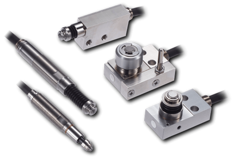
High Precision Positioning
- Stopper Bolt Switches Sensors -
Two-in-one unit. Stopper bolt with built-in switch
Click here ›Typical Applications of Stop Bolts
Stop bolts are widely used across industries for positioning and motion limitation. Below are typical applications.
Production Equipment and Machine Tools
In industrial machinery, stop bolts for position adjustment are used in many places.
When changing jigs on a production line, stop bolts enable accurate positioning and help reduce errors introduced by replacement.
Bolts are also used as stops to limit the travel of slide tables or arms on machine tools, often designed with lock nuts so they can be fine-tuned as needed.
To improve positioning accuracy and repeatability, they may also be combined with shock absorbers at the stopping point.
Automotive Components

Automobiles also incorporate various types of stop bolts.
Examples include adjustment screws for engines and transmissions, stoppers for clutch and brake pedals, bolts for door opening angle adjustment, and rubber-tipped stop bolts for hood height adjustment.
They are robustly secured to prevent shifting under vibration and may use resin pads or rubber parts to reduce impact and noise as needed.
In particular, hood and trunk stoppers often have rubber bumpers on the bolt tip, allowing fine adjustment of panel position and closing feel by tightening.
Material-Handling Systems and Industrial Robots

In belt conveyors and transfer equipment, stop bolts are used to define the workpiece stopping position.
They are combined with cylinder-type stopper units so the stop position can be changed according to workpiece size and adjusted quickly during line changeovers.
In industrial robots and automated assembly machines, bolts are built in as limit stops to physically restrict excessive motion for safety.
In some cases, adjustment bolts with impact-absorbing materials are installed to prevent mechanism damage during emergency stops.
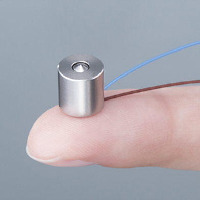
High Precision Positioning
- Micro-stopper Switches -
Compact size (8 x 8 mm dia.)Mountable on robotic fingertips
Click here ›Key Considerations When Selecting Stop Bolts
When selecting and designing stop bolts, pay attention to the following technical points.
Material Selection and Environmental Compatibility
It is important to choose the appropriate material and surface treatment for the operating environment.
In environments exposed to moisture or water, select corrosion-resistant stainless steel or anti-corrosion plated products. In coastal areas, A4-grade stainless steel or titanium screws with higher corrosion resistance are recommended.
When high strength or wear resistance is required, hardened alloy-steel screws (often with a black oxide finish) are suitable.
Also consider galvanic corrosion and galling due to dissimilar-metal contact, and use lubricants or surface treatments as countermeasures when necessary.
Proper Clamping Force and Thread Size
Overtightening a stop bolt can cause thread damage, rounding of the hex socket, or damage to the mating part.
When tightening with an L-shaped hex key, a practical rule of thumb is to hold the short arm and tighten until it flexes by roughly 30 degrees.
For size selection, a common guideline is that the stop-bolt diameter should be about half of the shaft diameter being secured: too small reduces holding force, while too large can weaken the part.
Resistance to Impact and Vibration
For applications subject to vibration or repetitive impacts, anti-loosening measures are essential.
In terms of tip shape, cup points and knurled cup points are particularly resistant to vibration-induced loosening.
For additional reliability, apply threadlocker (thread-locking adhesive) or use stop bolts with a nylon patch.
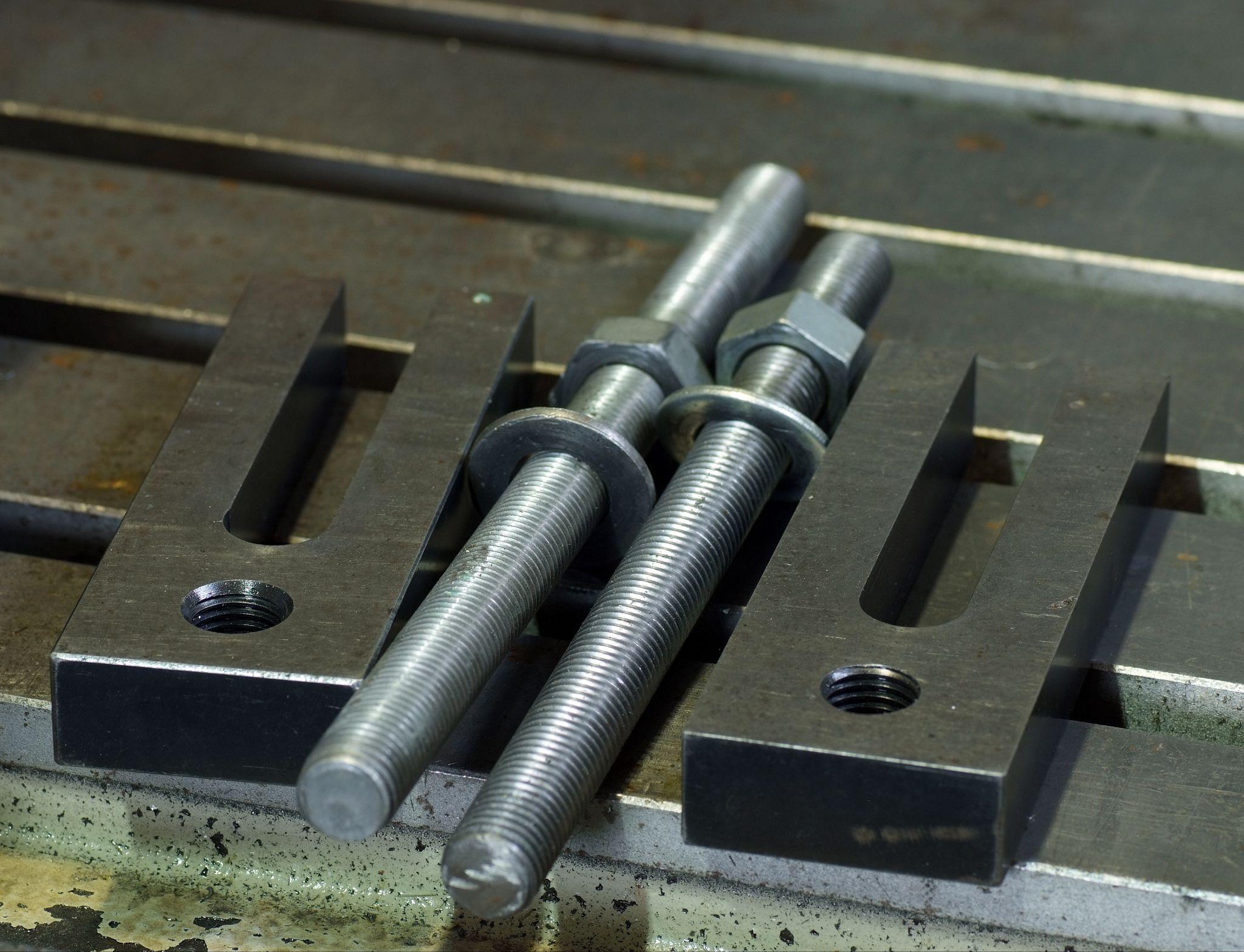
Another method is the double stop-bolt approach.
In this method, a smaller stop bolt is tightened on top of an already tightened one so the two screws press against each other and lock. The screws mutually prevent loosening, delivering a strong anti-loosening effect.
For stop bolts used as physical end stops, it is also important to prevent bending or shifting under impact by using cushioning materials (urethane or rubber) and by providing sufficient bolt diameter and strength margin.
Tip Geometry and Care for the Mating Part
As noted above, tip selection should match the application and the mating material.
Using a sharp cone point on a soft shaft can leave deep damage; considering future replacement and adjustment, a flat point or nylon-tipped type is preferable. When high torque transmission is required, machine a flat (bearing surface) on the shaft and press a cup point or dog point firmly against it to prevent slippage.
Adding a dimple (recess) or a flat surface helps prevent positional shift while increasing holding capability.
Conversely, in locations where appearance or surface finish matters, be mindful of pressure marks left by the stop bolt.
When choosing the tip, consider measures such as using a soft intermediate pad at the contact point or fixing the part at a location where indentations will not be an issue.
High Precision Positioning
- Stopper Bolt Switches Sensors -
Two-in-one unit. Stopper bolt with built-in switch
Click here ›Practical Advice for Product Designers
For designers and engineers who use stop bolts in manufacturing settings, the following summarizes practical points along with common issues and how to avoid them.
Tightening Control and Anti-Loosening Measures
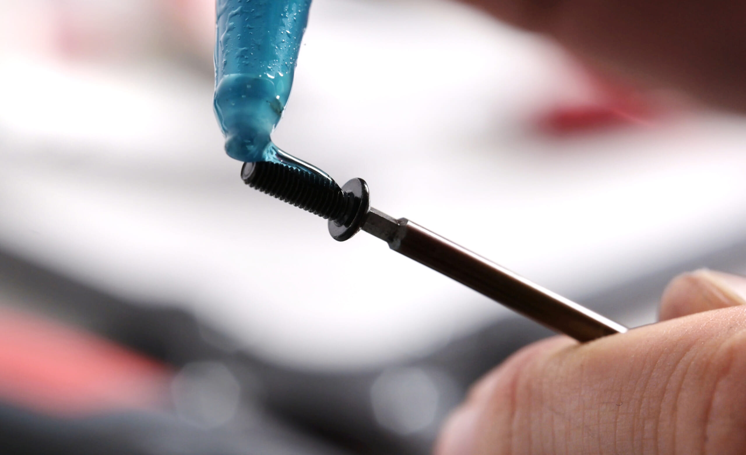
Because stop bolts are small, tightening by “feel” often leads to under- or over-tightening.
Define appropriate torque levels as an internal standard and develop the habit of tightening with tools that indicate torque.
In vibrating environments, loosening can occur over time, so consider applying threadlocker or using a “double stop-bolt” lock (similar in concept to double nuts). A low-strength threadlocker for small screws allows later adjustment while greatly reducing vibration loosening.
During periodic inspections, include stop-bolt tightness as a checklist item and retighten or refix as necessary.
Preparing the Right Mating Features
Don’t rely solely on the stop bolt—add design features to the component being fixed as well.
For example, adding a flat or a dimple to a shaft makes positioning with a stop bolt easier and reduces slippage even under high torque.
Especially for high-speed rotating shafts or high-load couplings, consider combining with a keyway and key or a split pin.
A safer design is to avoid forcing the stop bolt to carry loads by itself: limit its role to positioning and preload, and have the main load supported by other mechanisms.
Part Damage and Maintenance
If a stop bolt is tightened strongly, it can create indentations or deformation in the mating part.
While this can improve holding power, it may make readjustment or disassembly difficult. A typical problem is that a bearing can no longer pass over a shaft due to the embedded mark.
For critical locations, anticipate the impact of tightening marks in advance and consider measures such as preparing replacement parts, designing the joint so the tightening position can be shifted, or using screws with a soft patch on the tip.
Also, when reusing, inspect damage on the screw tip and the contact surface, and plan for replacement if abnormal wear or deformation is found.
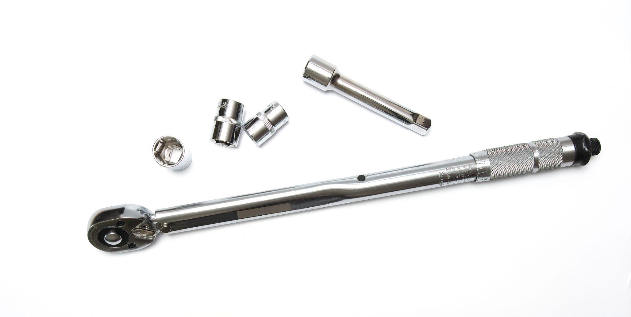
Assemblability and Tool Access

Because stop bolts are turned via small hex sockets or slots, pay attention to tool access during assembly and adjustment.
If placed in tight spaces, the wrench may only enter at an angle, preventing sufficient torque from being applied.
Check tool clearance in 3D beforehand and, if needed, use a longer screw to expose the driving section or provide an access hole.
With hex-socket screws, debris or paint in the socket can prevent the wrench from seating fully. If painting occurs later, mask with a temporary screw or clean with air blow before assembly.
Common Troubles and Countermeasures
Common failures include “forgetting to tighten the stop bolt, causing the shaft to slip out,” and “loosening due to vibration, leading to timing shifts and equipment malfunction.”
These can be minimized by thorough tightening control and double-locking (anti-loosening) measures.
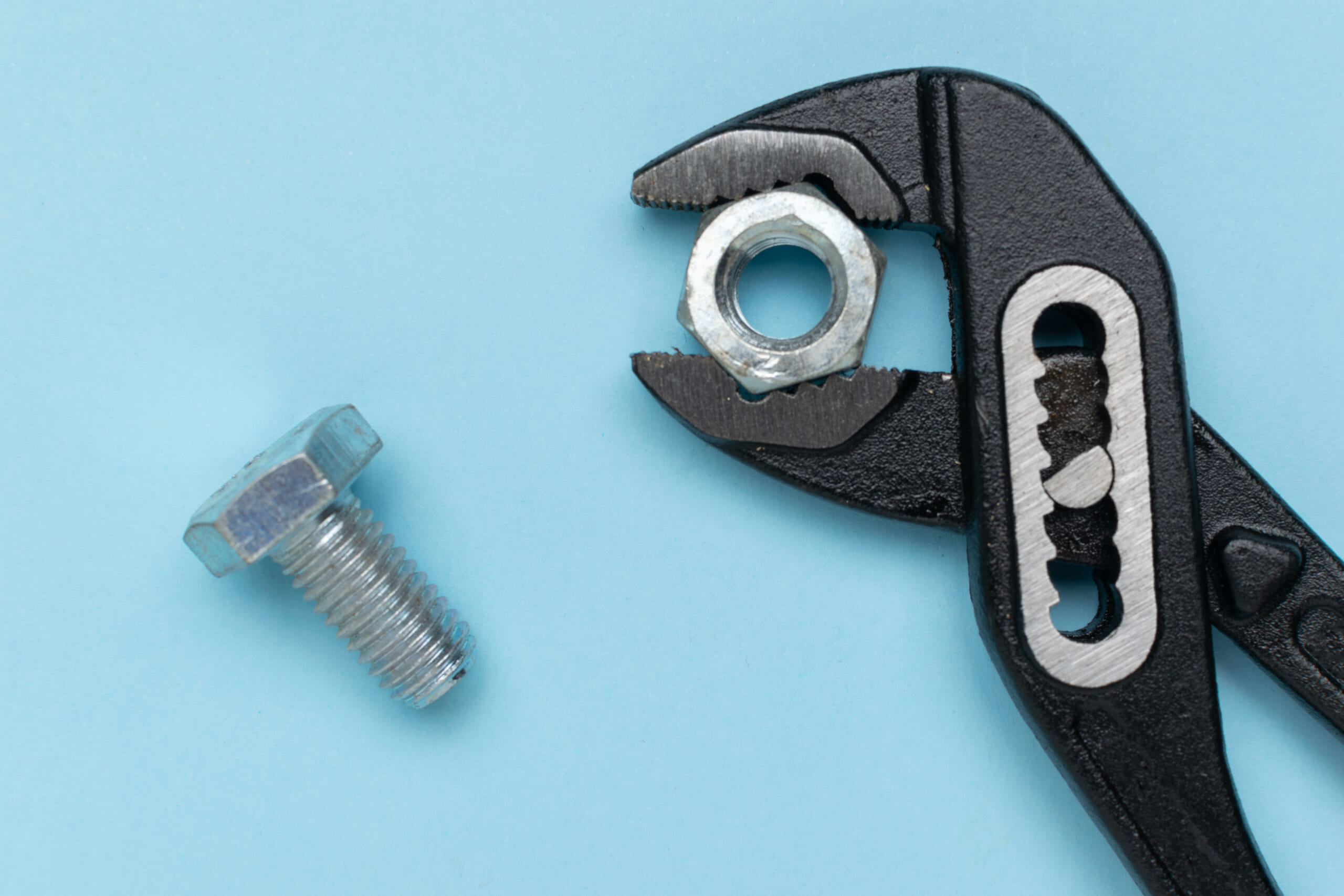
Another frequent issue is “over-tightening, stripping the hex socket so it can never be removed.”
This can be prevented with proper torque control, high-quality wrenches, and selecting the correct wrench size for the screw.
The smaller the stop bolt, the easier it is to round the socket due to tool wear or clearance from tolerances, so professionals often take care to use a fresh hex key as needed.
Finally, there are cases where “the holding force was weaker than expected and the shaft slipped.”
Possible causes include choosing an unsuitable tip shape, the mating material being too hard to bite into, or lubricating oil causing slippage.
Improvements include machining a flat on the shaft, changing the tip type (e.g., flat point to cup point), or degreasing and retightening.
High Precision Positioning
- Micro-stopper Switches -
Compact size (8 x 8 mm dia.)Mountable on robotic fingertips
Click here ›Advanced Use Cases and Practical Cautions in Machining Operations
Stop bolts are used in many situations and are indispensable for accurate positioning and for seating/locating mass-produced parts at a fixed position.
Below, from a practical shop-floor perspective, we introduce advanced ways to use stop bolts in machining centers and similar equipment, along with key cautions.
When Using Stop Bolts for Sheet/Plate Machining, Don’t Place Them Too Close to the Reference (Parallel) Surface
In mass-production machining of sheet/plate parts, dedicated fixtures are often used to keep positioning and clamp locations consistent.
When the Y-axis datum surface is set against a parallel pin and the X-axis datum surface is set against a stop created by a stop bolt, the workpiece mounts more stably if the stop bolt is placed as far from the parallel pin as possible while contacting near the center of the workpiece.
Especially when loading/unloading is handled by less experienced operators or part-time staff, it is important to position the stop so that mistakes are less likely.
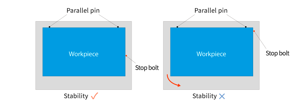
As shown on the left side of the figure, placing the X-axis stop away from the reference surface used for parallel alignment makes mounting easier. Conversely, as on the right side, if the X-axis stop is too close to the parallel reference surface, a rotational force acts in the direction of the red arrow, making accurate mounting difficult.
If machining proceeds while the workpiece has shifted in the arrow direction, parallelism is lost and dimensions from the datum surface deviate, resulting in defective parts.
If the shift is significant, problems may occur such as tool interference (e.g., an end mill) or drill breakage at the workpiece corner.
Therefore, installing the stop at a position that enables easy, accurate mounting—even for less experienced operators—leads to more efficient fixture design and fewer defects.
It’s Difficult to Determine Stop-Bolt Protrusion Solely From the Workpiece Position
In many cases, the stop position is fixed first, the workpiece is brought into contact, and then the origin is measured. However, in some situations the stop must be set after the workpiece is clamped and the origin coordinates are already defined.
However, it is very difficult to set the stop accurately to a position when the origin coordinates are predetermined.
This is because the stop’s protrusion can shift slightly while locking it in place with a nut or other anti-loosening method.
This can happen, for example, if only the fixture stop is damaged in an accident, or if an inexperienced operator accidentally removes the stop.
Skilled operators may be able to anticipate the shift caused by tightening the lock nut and return the stop to the correct position, but inexperienced operators may mis-set the stop—potentially leading to mass defects if machining continues.
If such a problem occurs, promptly notify your supervisor or manager and take appropriate action. Quick and accurate reporting, communication, and consultation can be the “stopper” that prevents large-scale defects or the outflow of nonconforming products.
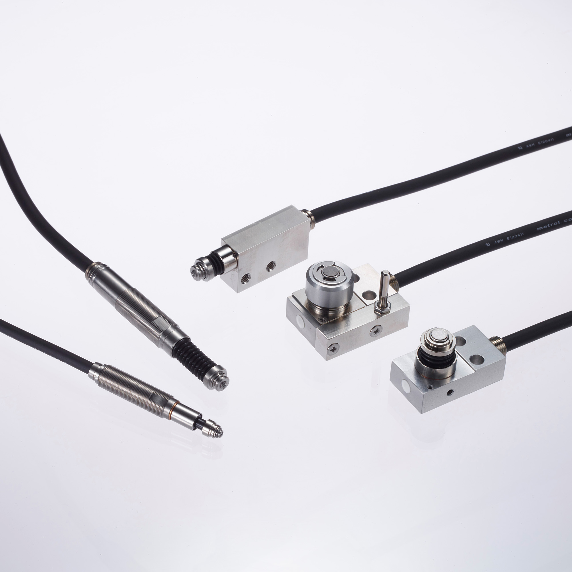
What Are Metrol’s High-Precision Positioning Sensors?
In machine tools and industrial robots, positioning components with accuracy on the order of a few micrometers is a crucial factor that strongly influences productivity and quality.
High-precision positioning sensors from Metrol, a Japanese measurement-instrument manufacturer, deliver world-class performance with repeatability up to 0.5 µm and operate stably even in harsh environments.
With a lineup of more than 200 models, they cover a wide range of applications—from machine-tool datum/origin setting to tool breakage detection and workpiece seating confirmation.
They are highly regarded at manufacturing sites in Japan and overseas as next-generation positioning solutions that combine accuracy, durability, and energy efficiency—far beyond a simple switch.
High-Precision Positioning Touch Switches
These are contact-type high-precision switches used for positioning and workpiece presence detection in machine tools, robots, and jigs. They achieve an extremely high repeatability of up to 0.5 µm and feature IP67-rated waterproof and dustproof protection, ensuring stable operation even in harsh environments. With more than 200 standard models available, they offer a wide range of variations, including designs for confined spaces, high-temperature environments, vacuum applications, and low contact force requirements.
Tool Setter (Tool Length Measurement Sensor)
This is a contact-type sensor installed on CNC machine tools and industrial robots for tool length measurement, reference position setting, and tool breakage detection. By automatically measuring and compensating for tool length, wear, and thermal displacement inside the machine, it helps prevent machining defects and significantly reduces setup time. It is one of Metrol’s best-selling products, with a proven track record of more than 500,000 units shipped in 74 countries worldwide.
Touch Probe (On-Machine Measurement Probe)
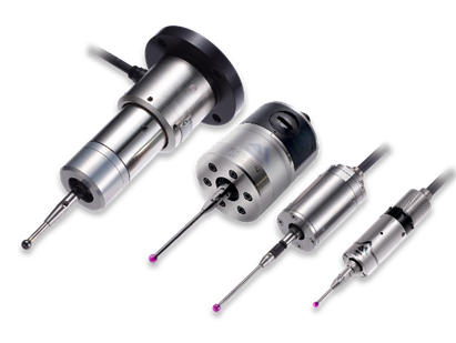
This is a contact-type probe for in-machine measurement, installed on machine tools and robots to automatically perform workpiece positioning (centering) before machining and dimensional measurement after machining. With a repeatability of 1 µm, it automates workpiece referencing and dimensional inspection, replacing skilled manual operations to reduce setup time and help prevent machining defects. Both wired and wireless models are available, meeting retrofit needs for 5-axis machining centers and robotic applications.
Air Gap Sensor (Pneumatic Sensor)
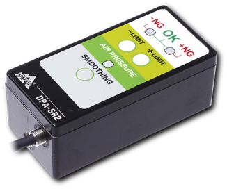
This is a non-contact sensor that uses air pressure to detect workpiece seating conditions with micron-level accuracy. It can detect gaps (“lift”) of less than 10 µm—previously difficult to measure—with a repeatability of ±0.5 µm, helping prevent machining defects and equipment downtime caused by insufficient contact between the workpiece and fixture. The sensor is used in applications such as semiconductor manufacturing processes, precision part clamping operations, and grinding wheel positioning on grinding machines, and it is a smart sensor that also supports the international standard IO-Link communication.