What Are Cutting Tools? A Complete Guide to Types, Importance, and Troubleshooting
Cutting tools are indispensable in manufacturing and machining operations. If their roles and types are not properly understood, issues such as incorrect tool selection or machining defects can occur.
In this article, we clearly explain practical, on-the-job information—from the basics of cutting tools and the characteristics of each type to common shop-floor problems and how to address them.
Table of Contents
What Are Cutting Tools? Types and How to Choose Them
A cutting tool is a general term for tools (blades) mounted on machine tools to remove material and machine a workpiece into the desired shape.
In machining, unnecessary portions are removed from materials such as metals or resins to produce parts.
For example, there are many types of cutting tools—such as drills familiar from DIY, end mills used on milling machines, and lathe tools (single-point tools) used on lathes—and they are selected according to the machining objective.
Main Types of Machining (Turning, Milling, and Drilling)
To understand the role of cutting tools, first review the main machining methods. Machining can be broadly classified into the following three types.
| Type of Machining | Characteristics | Photo (Image) |
|---|---|---|
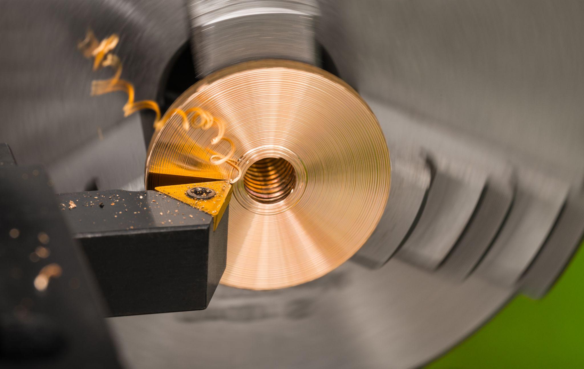
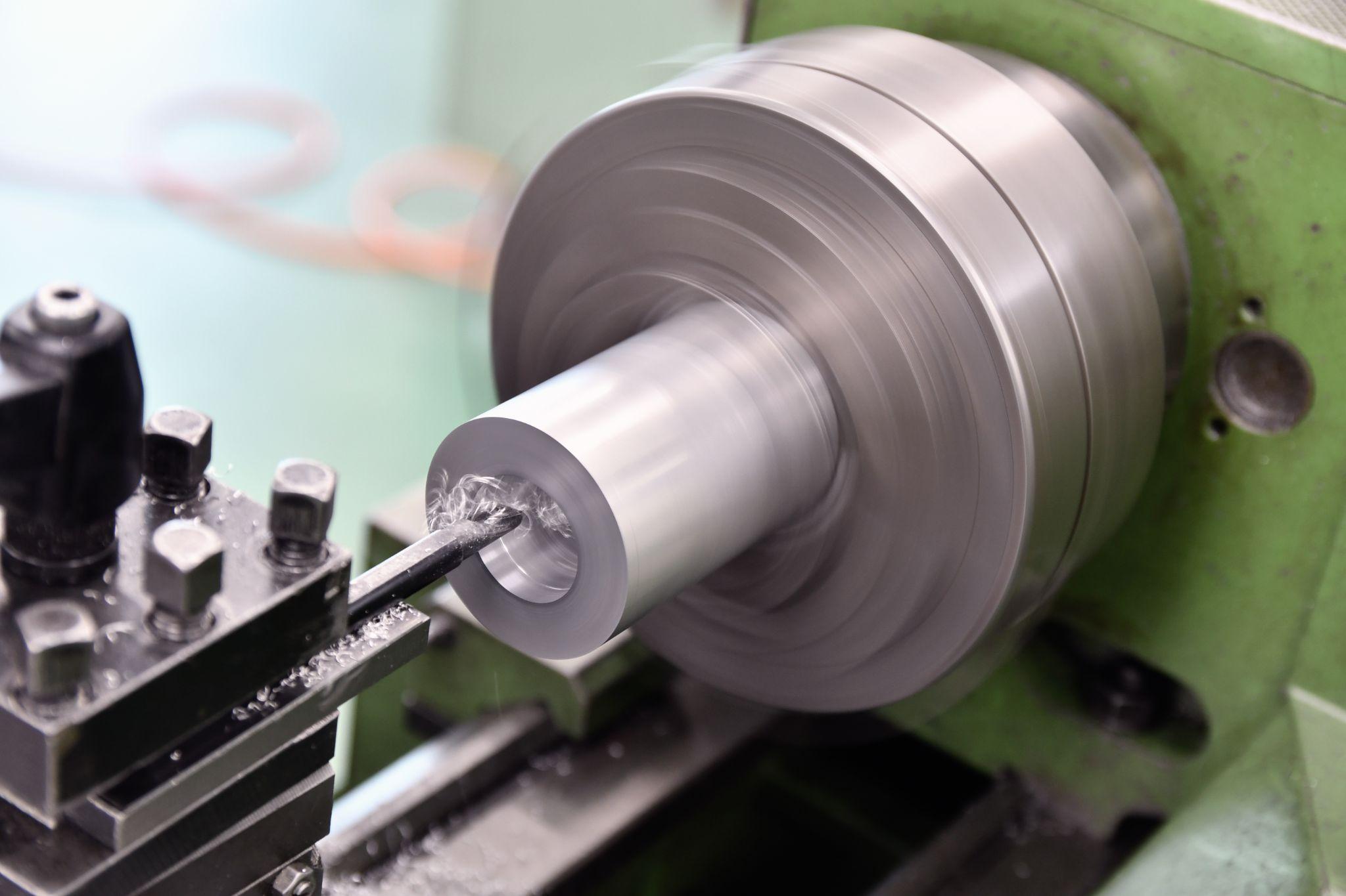
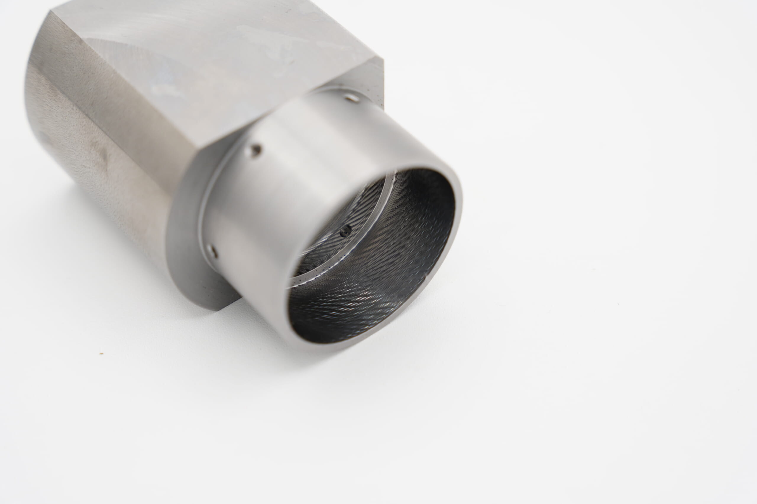
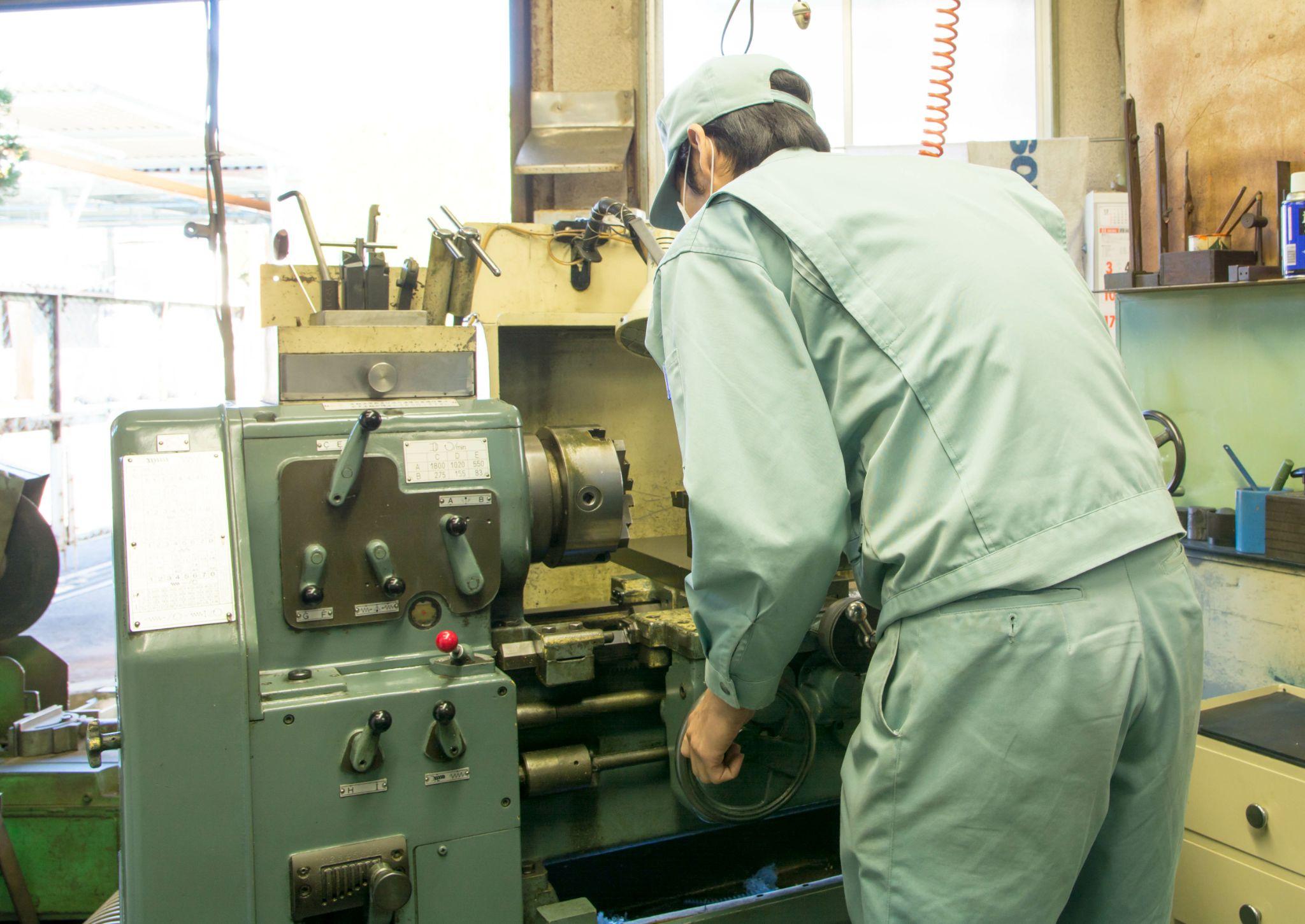
| Turning | A machining method performed on a lathe, where the workpiece (material) is rotated and a tool such as a lathe tool is applied. It is mainly used for turning the outside diameter of cylindrical materials, drilling, boring (machining the inside of a hole), and threading (cutting external and internal threads). | 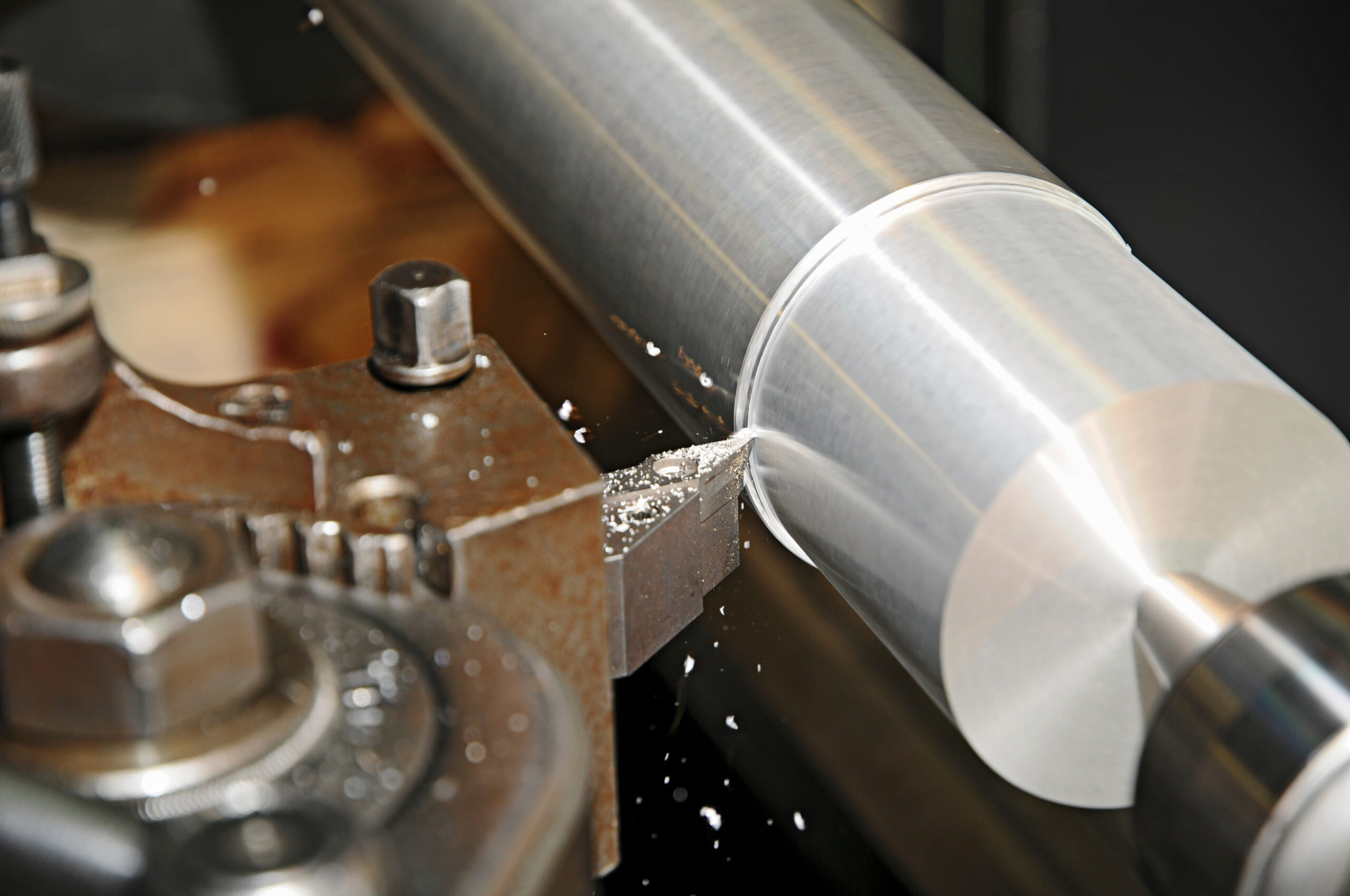 |
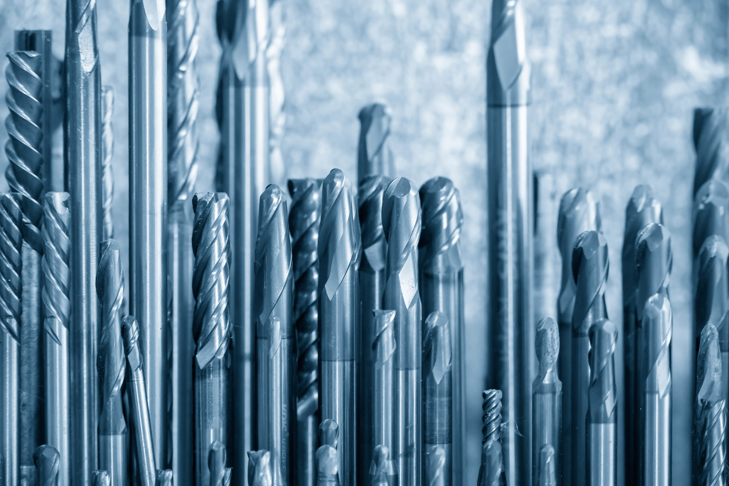
| Milling | A method in which the workpiece is fixed and a tool such as an end mill is rotated at high speed to remove material. It supports a wide range of operations, from face milling and slotting to machining complex 3D shapes. | 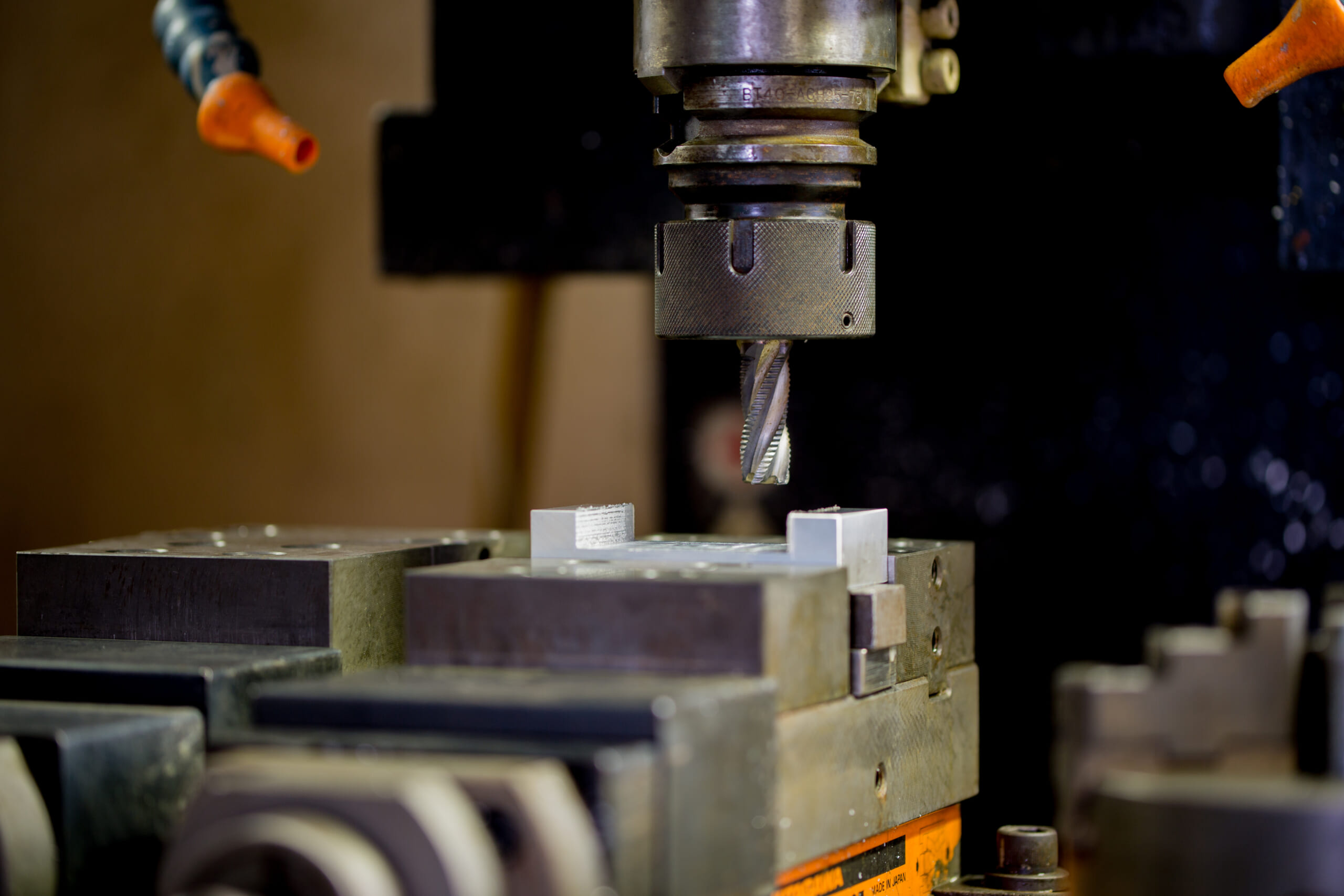 |
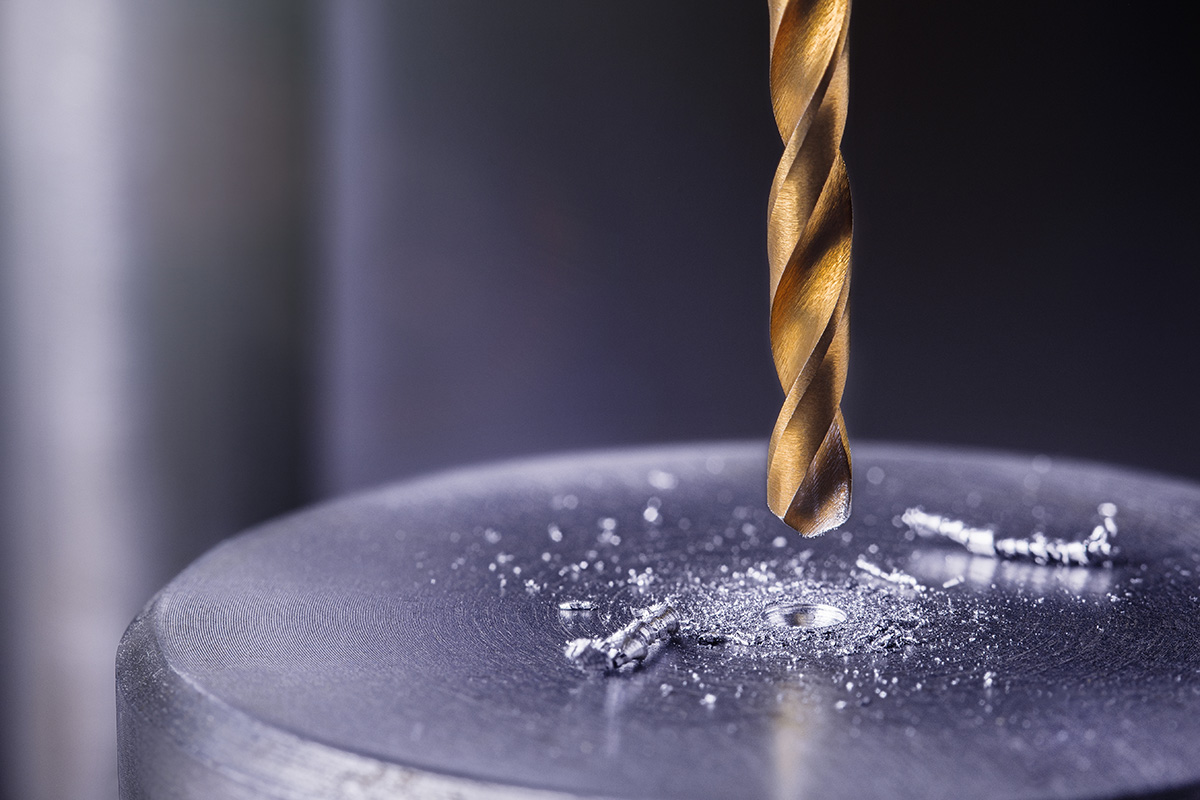
| Drilling | A process that creates holes using a drill, performed on drill presses or machining centers. After drilling, it also includes hole finishing to diameter using a reamer and thread cutting using a tap (so-called “threading”). | 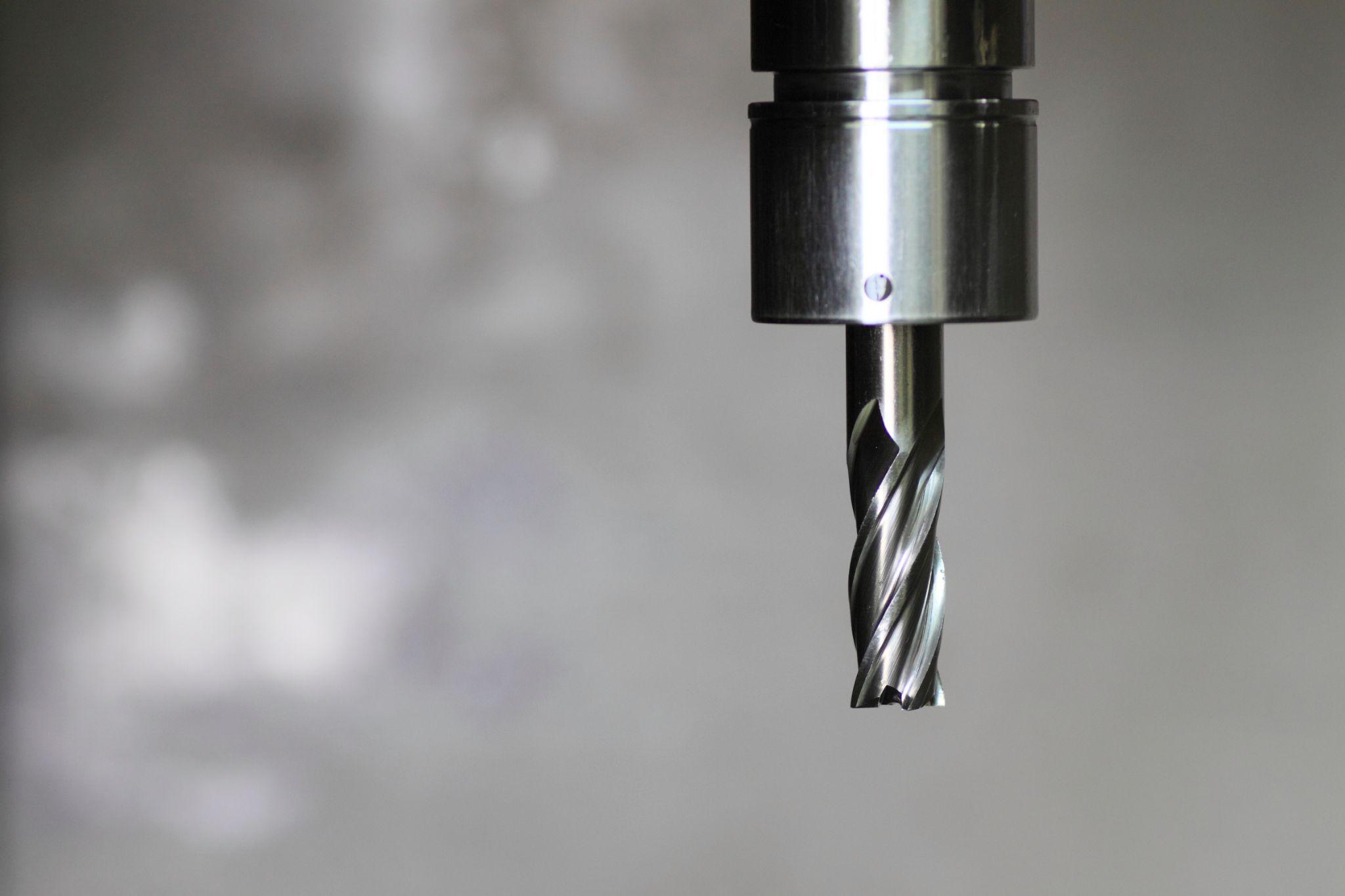 |
As described above, the cutting tools used also vary depending on the machining method.
Types of Cutting Tools and Their Applications
Cutting tools come in many forms depending on their shape and application. Below is a summary of representative tools and their characteristics.
| Types of Cutting Tools and Their Applications | Characteristics | Photo (Image) |
|---|---|---|
| End mill | A rotating tool used on milling machines and machining centers, with cutting edges on the tip and sides. It is a versatile, general-purpose tool used for face milling, side milling, and slotting, and is widely used from mold machining to general part machining. | 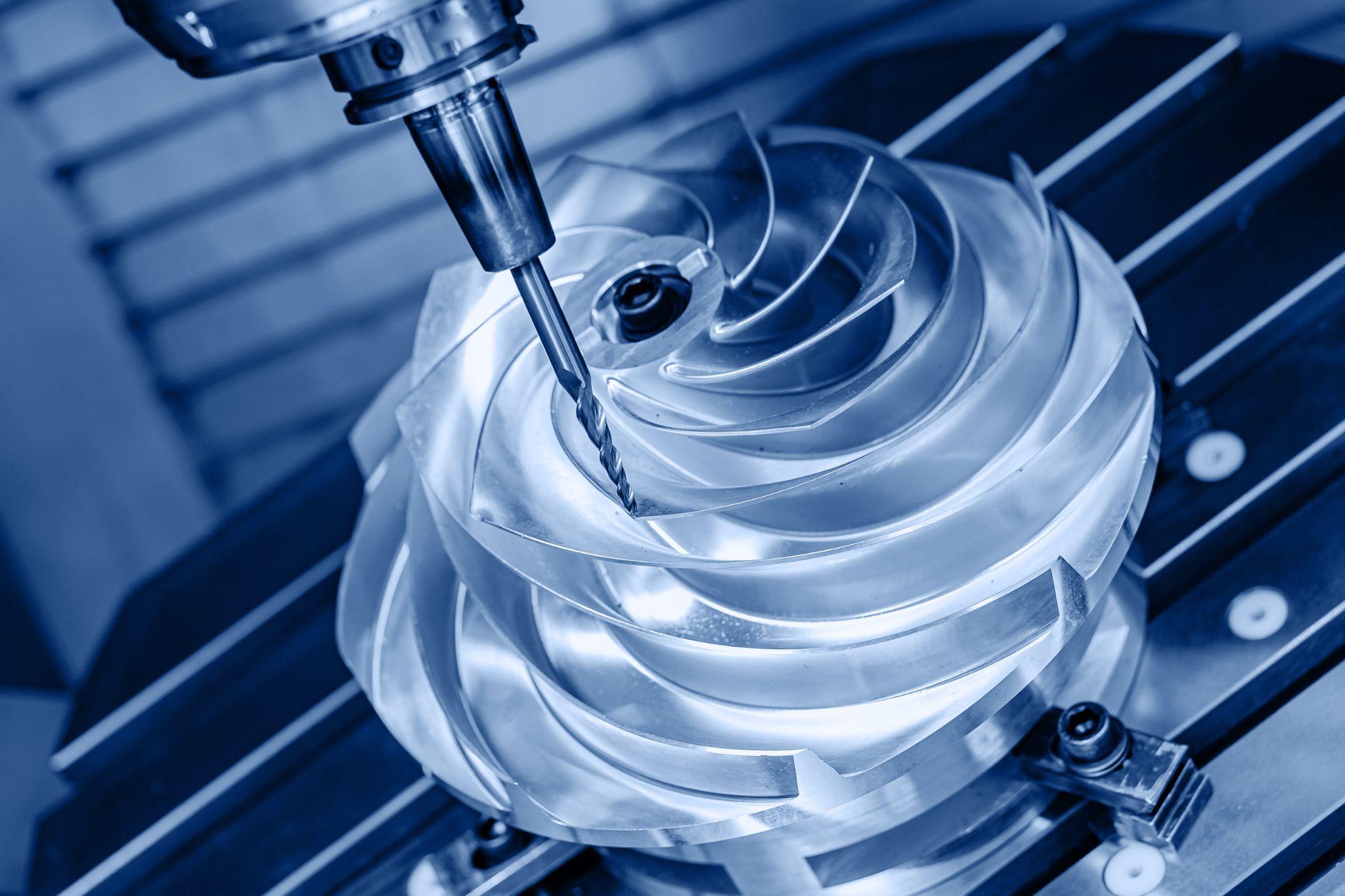 |
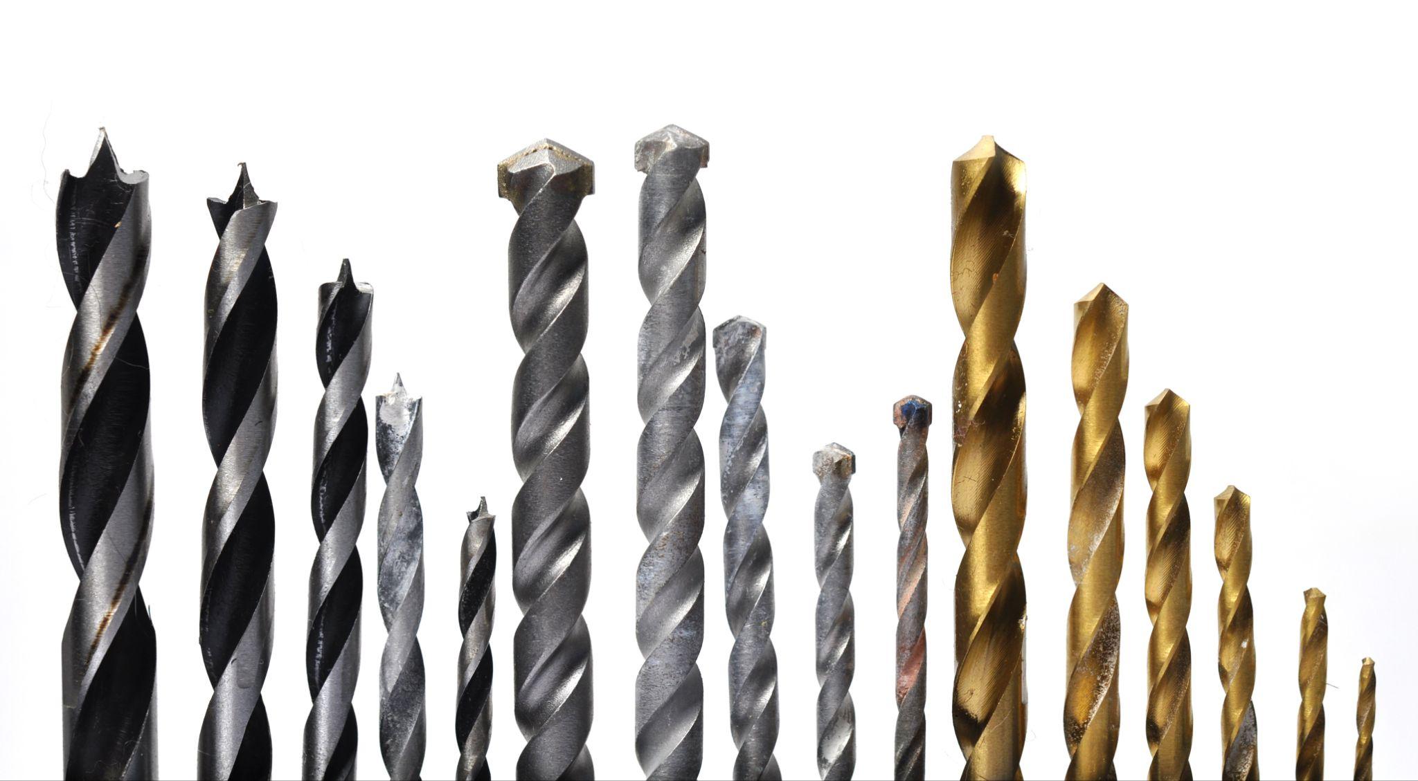
| Drill | A tool dedicated to drilling, used to create round holes in a workpiece. The most common type is the twist drill, which has a shape that facilitates chip evacuation during machining, and there are variants suited to different hole depths and diameters. |  |
| Tap | A tool used to cut internal threads in a pilot hole. The tap is screwed into a drilled hole to cut the thread profile and create internal threads. | 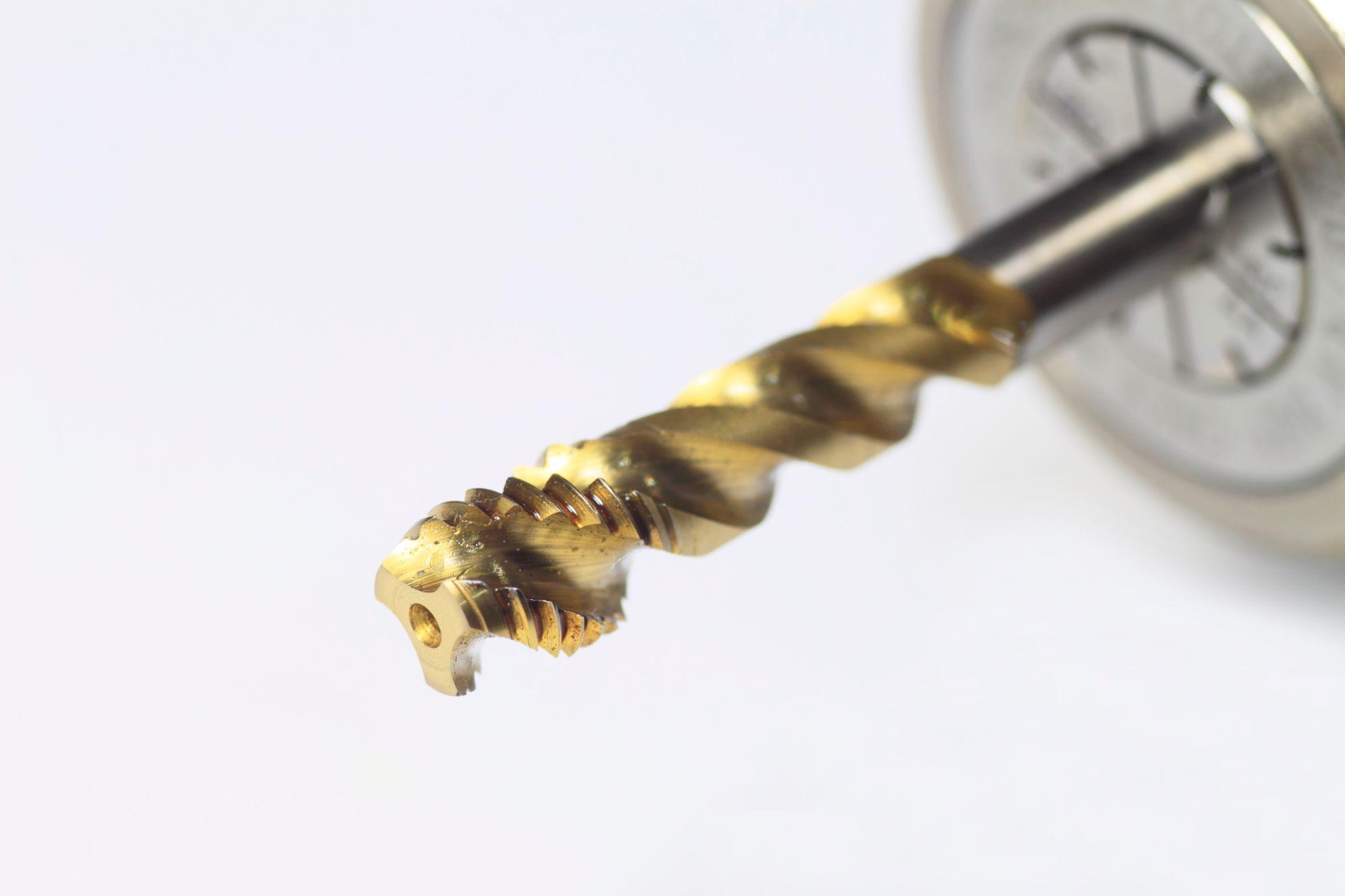 |
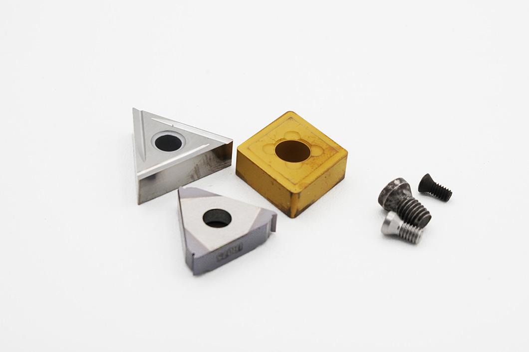
| Lathe tool (single-point tool) | A single-point tool used on lathes for turning, where material is removed while the workpiece rotates. A common type uses a replaceable insert at the tip; by changing the cutting-edge geometry, it can support a wide variety of operations. | 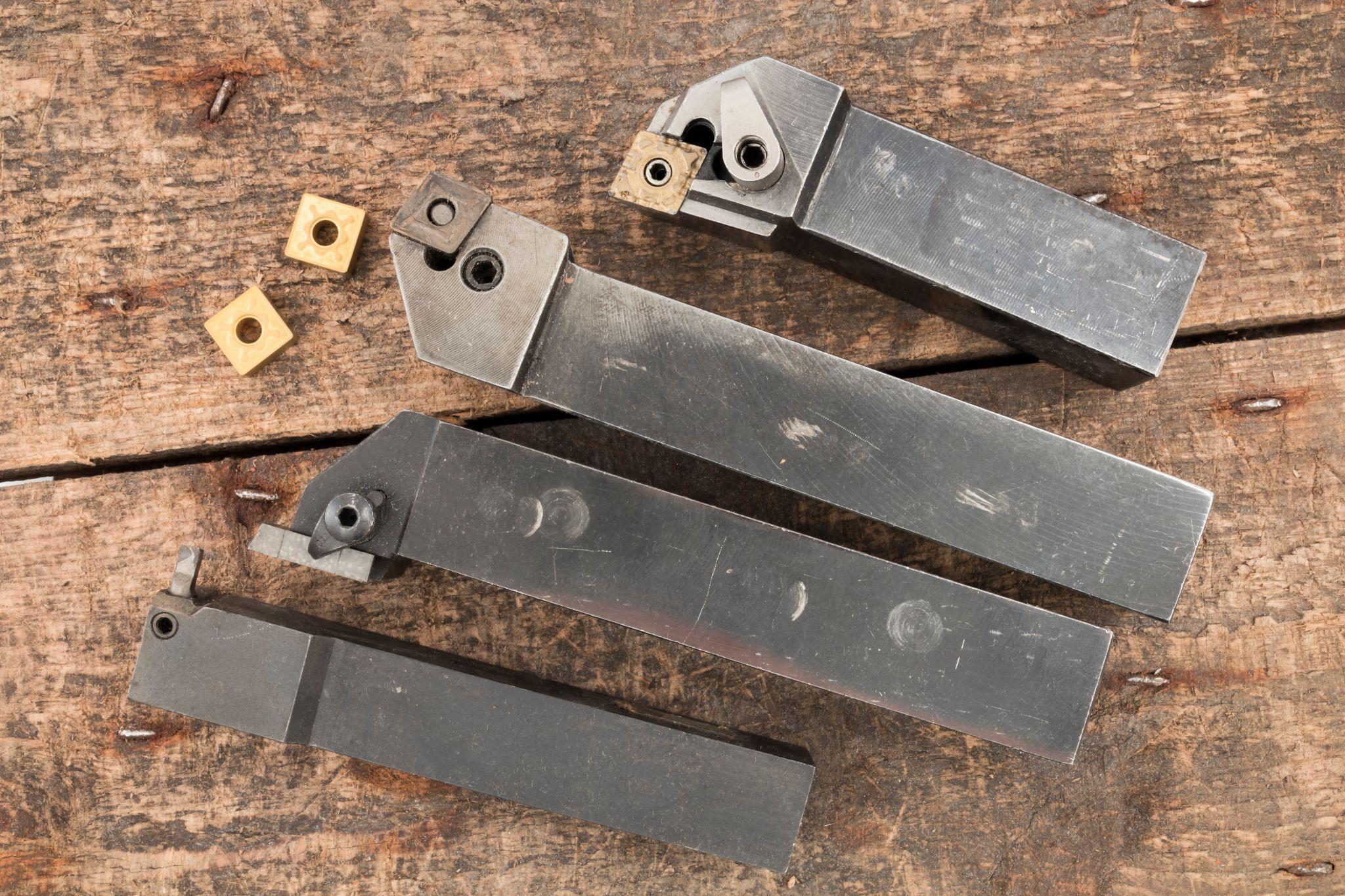 |
| Reamer | A finishing tool used after drilling. Inserted into a drilled hole, it removes a small amount of material to bring the hole diameter to high precision and improve surface finish. | 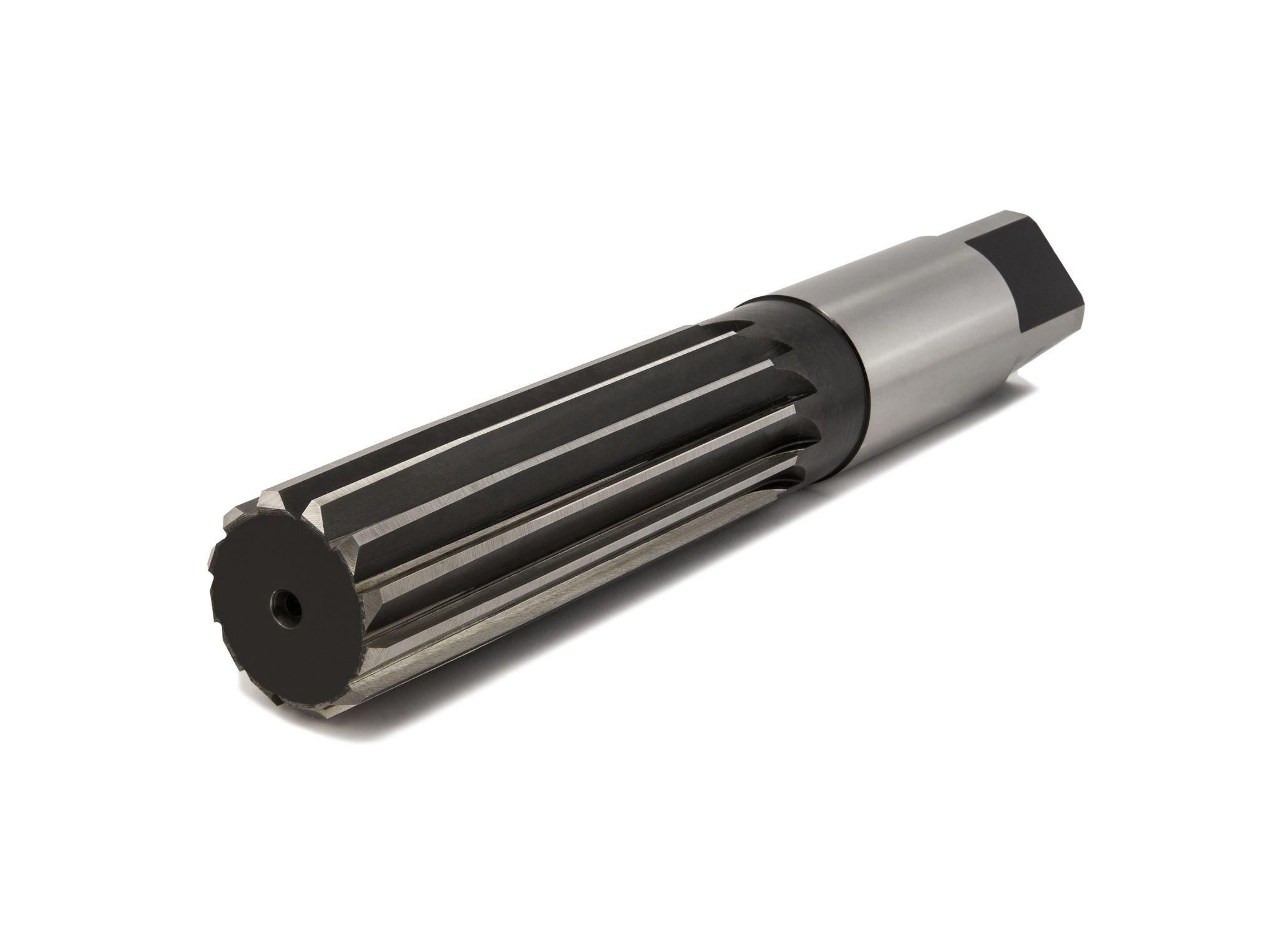 |
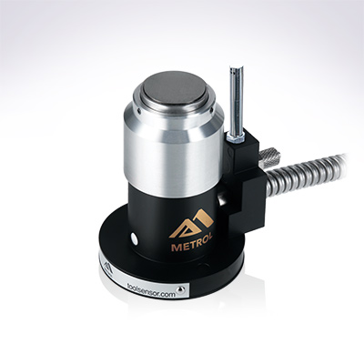
Automates originating of cutting tools
- Tool Setter -
Tool length and chips are monitored to prevent machining defects due to wear and thermal displacement
Click here ›Cutting Tool Materials and Selection Criteria
The performance of cutting tools is strongly influenced by their material.
The basics of tool selection are to choose a suitable tool geometry, material, and coating for the “work material and hardness,” “machining method (turning, milling, etc.),” and “required accuracy.”
Selecting the right tool for the job can significantly improve machining efficiency, tool life, and finished accuracy. Conversely, using a tool with an unsuitable material or geometry for the application can accelerate wear or edge chipping, so caution is required.
Refer to tool manufacturers’ catalogs and technical documentation to select the optimal cutting tool for your work material and machining requirements.
Major cutting tool materials and their characteristics are as follows.
- Tool steel (carbon tool steel / alloy tool steel)
A relatively low-cost steel for cutting tools. Because it is not extremely hard and is weak against heat, it is used for low-speed machining and for certain tools such as reamers.
Today, since higher-performance materials have become widespread, the use of tool steel is limited.
- High-speed steel (HSS)
An alloy tool steel made by adding tungsten and other elements to tool steel to increase hardness and heat resistance. Also called HSS, it is widely used for tools such as drills and taps that operate at relatively low to medium speeds. While it has high toughness and resists chipping, it does not retain hardness at high temperatures as well as carbide, so it tends to wear faster in high-speed cutting.
- Cemented carbide
A tool material made by sintering hard particles such as tungsten carbide with a binder such as cobalt. Because it is extremely hard and retains hardness at high temperatures, it is suitable for high-speed cutting and machining hard materials. It is the mainstream tool material today; however, since its toughness is somewhat low and it is vulnerable to impact, care is needed because the cutting edge can chip under sudden engagement or interrupted cutting.
- Ceramic
Tools made of ceramic materials. They offer heat resistance and wear resistance exceeding carbide, enabling very high-speed cutting of cast iron and difficult-to-machine materials. On the other hand, they are brittle and weak against impact, so they are mainly used for continuous cutting under stable conditions.
- CBN (cubic boron nitride)
An ultra-hard material with hardness second only to diamond, particularly effective for finishing hardened steels and other high-hardness materials. It also withstands high temperatures and is used in turning inserts and similar tooling for high-speed machining of steels. While very expensive, it offers long tool life and can contribute to cost reduction by replacing grinding processes.
- Diamond
The hardest material, suitable for high-speed machining of non-ferrous metals and non-metal materials such as aluminum alloys, copper, and carbon fiber reinforced plastics (CFRP). It offers extremely high wear resistance. However, it cannot be used for machining steel because it reacts with the tool at high temperatures. It is mainly used for finishing to achieve near-mirror surface accuracy.
How Cutting Tools Relate to Machine Tools
Cutting tools do not function on their own; they must be mounted on machine tools such as milling machines or lathes. Here, we explain tooling used to connect and hold tools to the machine, as well as automatic tool changing.
Tooling (Tool Mounting) and Standards
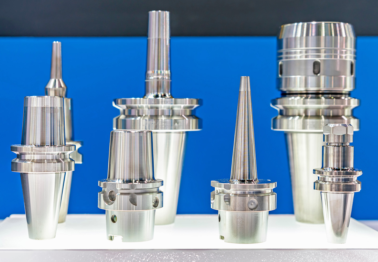
To mount a cutting tool on a machine tool, components called a tool holder and a shank are required.
The tool holder is a holding device that firmly grips the tool body, such as an end mill or drill, while the shank refers to the stem portion (a tapered mounting section) used to attach the holder to the machine spindle.
Each machine has defined shank standards (shape and size), and selecting and using appropriate tooling is key to improving machining accuracy and preventing problems.
For example, processes requiring high rigidity may call for a thick, short holder, while micro-machining may require a high-precision collet chuck—decisions like these are necessary.
Also, if the shank standard does not match the machine, the tool cannot be mounted. Therefore, it is important to confirm your machine’s shank type (e.g., BT or HSK) when purchasing tools.
Automated Tool Changes and Machine Tools
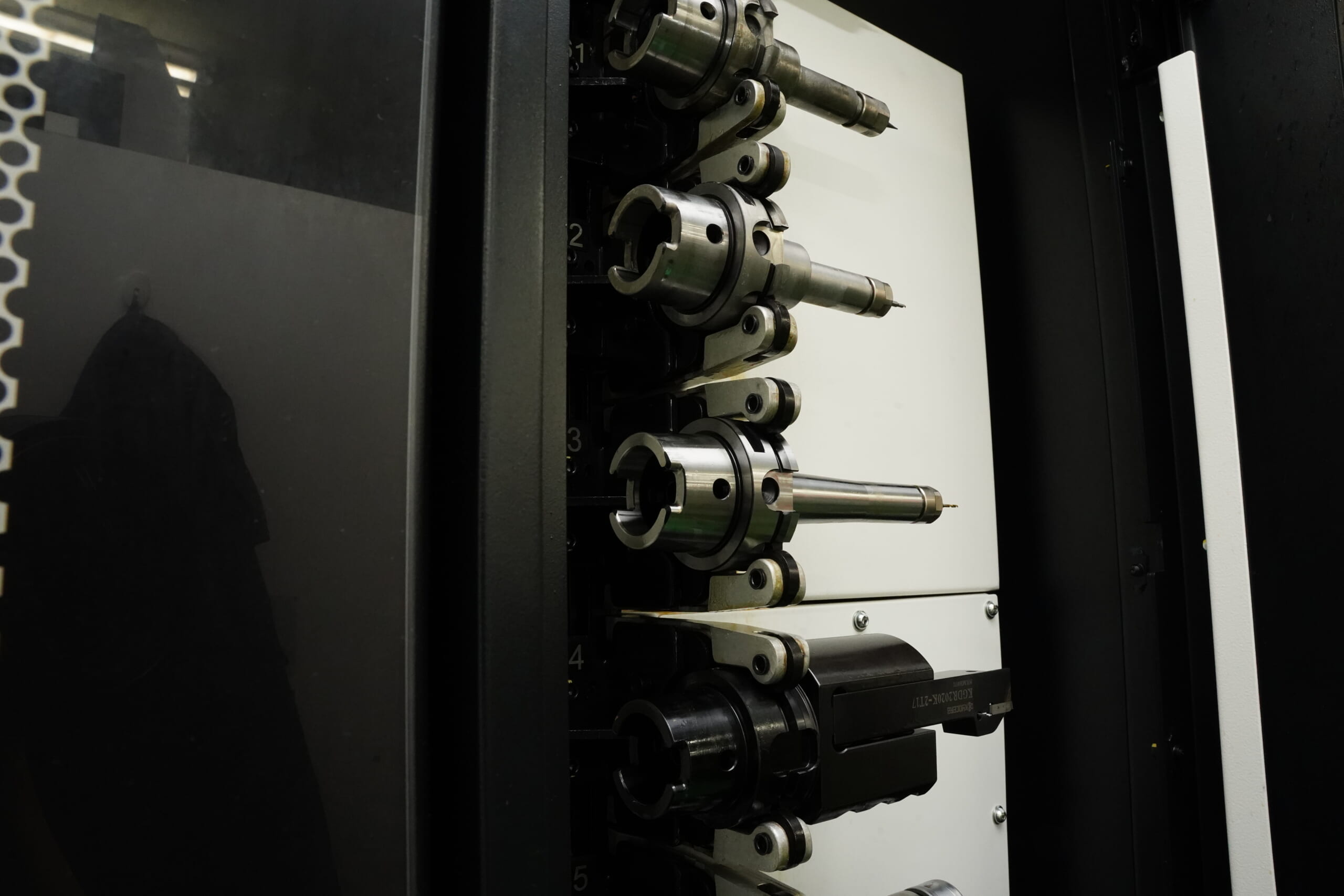
In recent years, it has also become common to store multiple tools in a machine’s tool magazine and automatically change tools according to the machining program (ATC: Automatic Tool Changer).
For example, on a machining center, tools can be changed automatically during a cycle—from an end mill for milling to a drill for hole making, and even a tap for thread cutting—enabling continuous machining.
Automated tool changes reduce setup time and enable unattended operation, dramatically improving productivity. However, if tool holder mounting accuracy or runout is poor, positional deviations can occur with each change, so regular maintenance and accuracy checks are necessary.
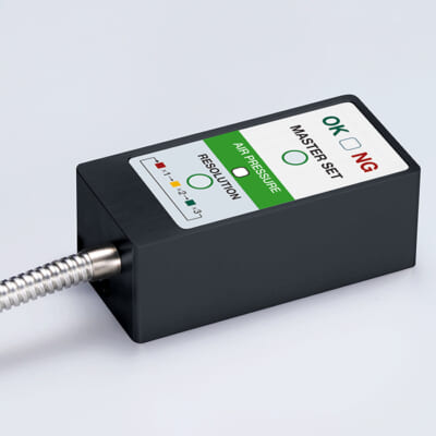
High-precision seating confirmation of workpiece and jig
- Air Gap Sensor -
You can check not only "presence/absence" but also "adhesion (gap)" at the same time with a repeatability of ±0.5 μm.
Click here ›Common Cutting Tool Problems and How to Handle Them
In advanced machining environments, tool-related issues often hinder production efficiency. Below, we explain representative problems commonly seen with cutting tools, along with their causes and countermeasures.
Tool Wear and Countermeasures
Wear is a phenomenon in which a cutting edge gradually abrades through repeated cutting, reducing sharpness. Tool wear is unavoidable with use; however, if cutting speed is too high or the work material is hard, heat generation increases and wear progresses rapidly.
The basic countermeasures for tool wear are setting appropriate cutting conditions and selecting suitable tool materials and coatings. By referencing the tool manufacturer’s recommended cutting speed, feed rate, and depth of cut—and machining under reasonable conditions suited to the work material—you can suppress wear progression.
Edge Chipping / Tool Breakage and Countermeasures
Chipping is a phenomenon in which a tool’s cutting edge fractures in small pieces, resulting in edge loss. Carbide and ceramic tools are hard but have low toughness, so their edges tend to undergo micro-fracture due to impacts or fluctuations in cutting load.
It is important to select tools appropriate for the work material and machining content. Choose carbide or CBN tools for hard materials, and choose tool materials with higher toughness for operations subject to impact—rather than using an unsuitable tool.
Also, replace a tool with a damaged edge as soon as possible—never continue using it as-is. Continuing to use a chipped tool not only causes dimensional errors and poor surface finish, but also makes chatter more likely, worsening the situation.
Chatter (Chattering Vibration) and Countermeasures
“Chatter” is a common term for the phenomenon in which the tool or workpiece vibrates during cutting. Also called “chattering vibration,” it appears as periodic vibration noise during machining and as uneven patterns on the machined surface (chatter marks).
Chatter countermeasures must be implemented from multiple angles depending on the root cause.
For tool selection, use the thickest, most rigid tool possible, and choose an appropriate number of flutes (in some cases, fewer flutes can reduce cutting resistance and be advantageous). Tools designed to suppress vibration can also be effective.
Next, for setup and mounting, keep tool overhang as short as possible and firmly clamp the workpiece using a rigid fixture. Also inspect the machine in advance for play or looseness, and if necessary, adjust spindle preload and take other measures.
Revising cutting conditions is also a powerful approach. In many cases, simply changing spindle speed slightly can avoid resonance and eliminate chatter.
Preventing Problems Through Proper Cutting Tool Management

Here we summarize key points to prevent problems through daily tool management and maintenance, and to maximize tool performance. Even excellent tools cannot perform as intended if they are not properly managed.
Understanding Tool Life and Planned Replacement
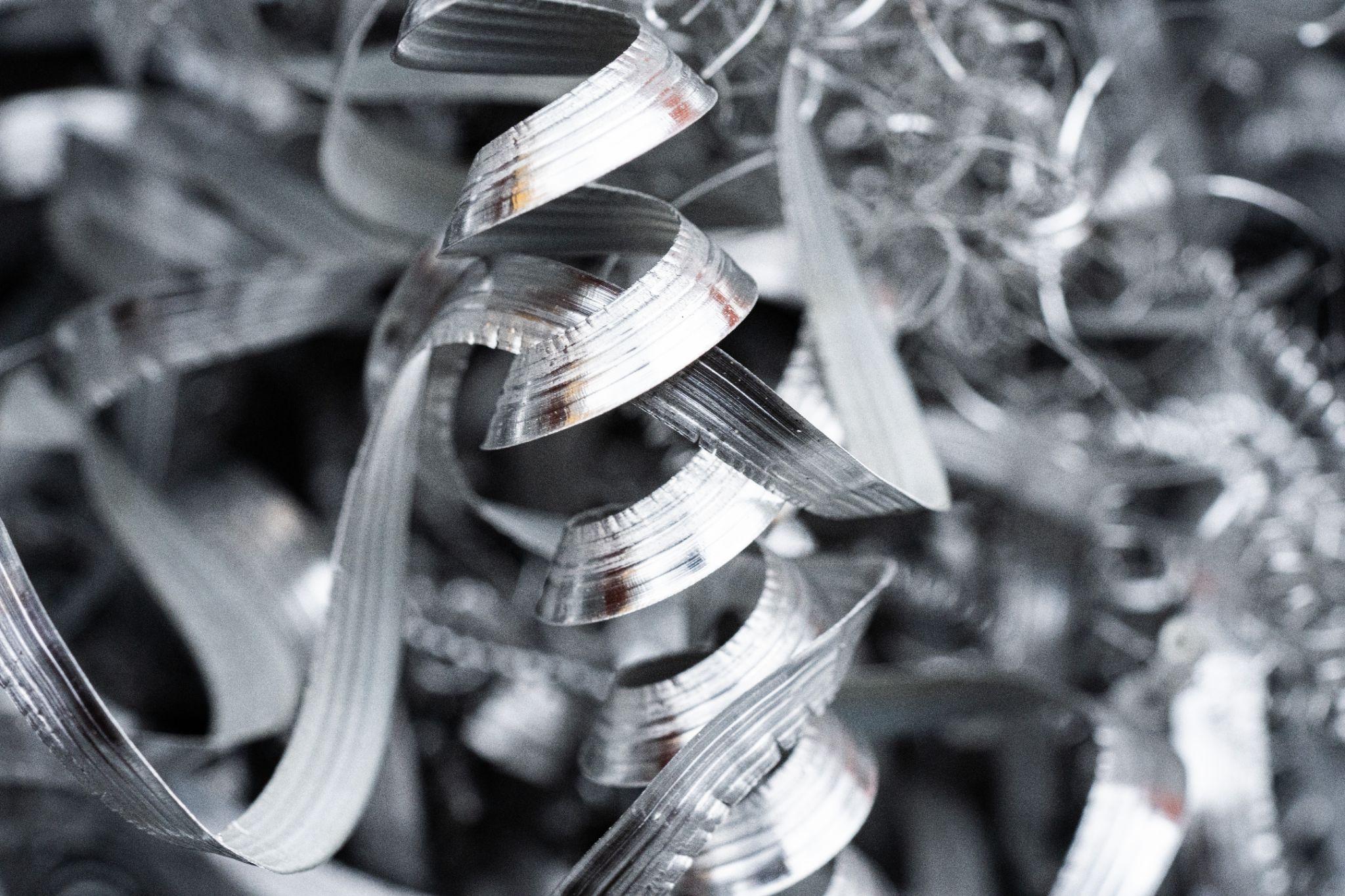
Each cutting tool has a service life. On the shop floor, tools are often replaced when operators judge that the tool has reached end of life based on reduced machining accuracy or changes in chip shape (e.g., becoming powdery).
However, it can also be effective to establish experience-based criteria—such as “replace after producing X parts”—and proactively switch to a new or reground tool before it reaches end of life.
Using Regrinding and Insert Replacement
A common practice is to regrind worn tools to restore the cutting edge. Sending tools to a regrinding service before the edge becomes fully worn or burnt allows tool life to be extended multiple times and helps reduce tooling costs.
While expensive special tools are often designed to be reground multiple times, insert-type tools are renewed by periodically indexing (flipping/rotating) the disposable insert to a fresh cutting edge.
The key point is not to continue machining with worn or chipped cutting edges. Properly managing insert inventory—and placing replenishment orders before you run out of usable edges—is also an important part of tool management.
How to Clean and Store Tools
After use, carefully wipe off attached chips and dirt with a cloth. If water-soluble coolant was used, dry the tool and apply rust-preventive oil. In particular, HSS tools are prone to rust, so be sure to take anti-corrosion measures.
Because carbide tools are very hard and their cutting edges can chip easily, avoid bumping them against other tools or dropping them. When storing, use cases or edge caps so that tools do not contact each other directly. Always manage tools in a clean and safe condition.
Tools are consumables, but with proper management, both tool life and cost can be greatly improved.
High-precision seating confirmation of workpiece and jig
- Air Gap Sensor -
You can check not only "presence/absence" but also "adhesion (gap)" at the same time with a repeatability of ±0.5 μm.
Click here ›Practical Tips from Experienced Machining Professionals
Always Cover Tools Stored in a Tool Stand
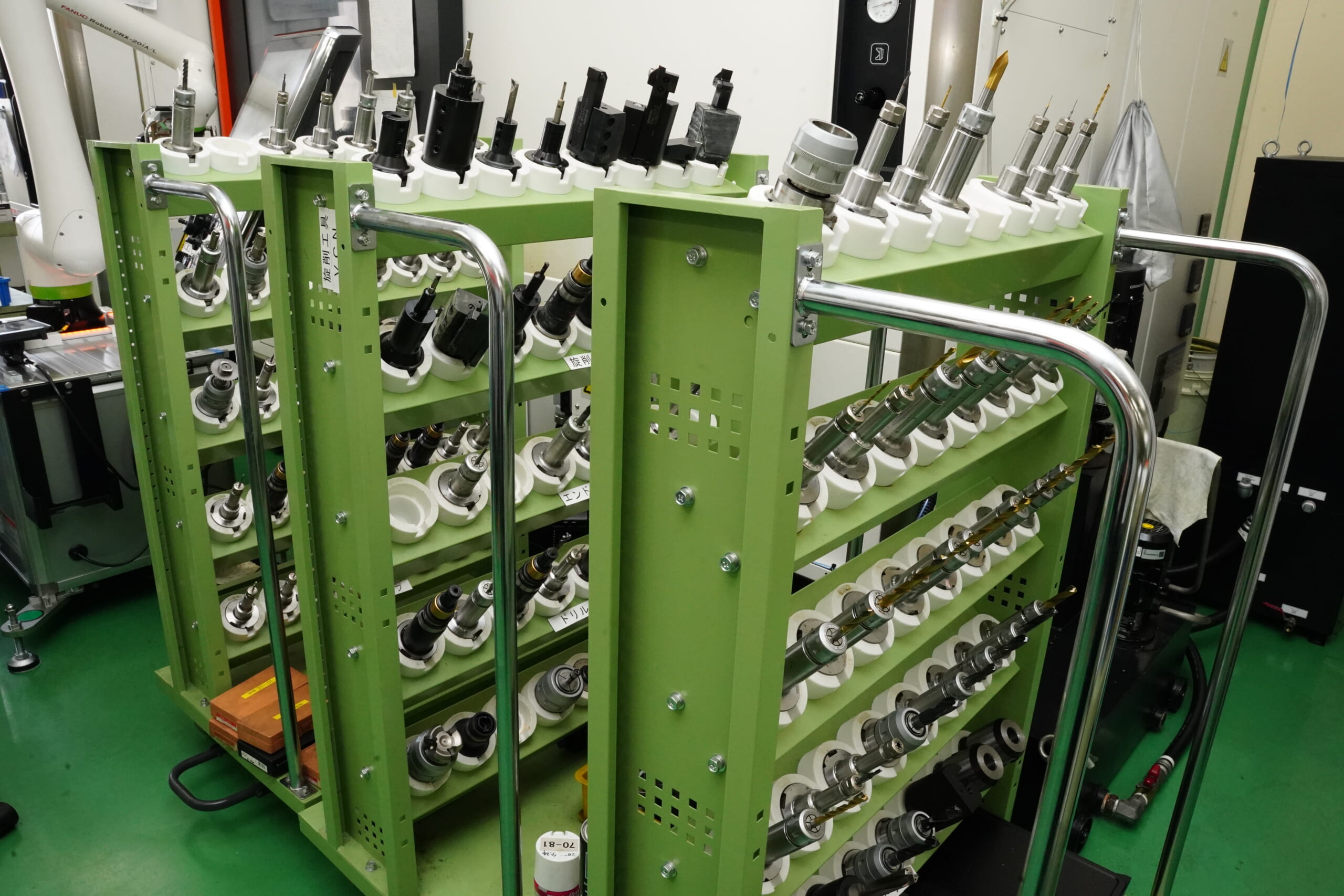
When placing shared tools on a tool stand for use across multiple machines, cover the cutting edges to protect them so they are less likely to be damaged even if they collide with neighboring tools.
In particular, carbide end mills and throwaway inserts are prone to chipping from impact, so store them in a way that prevents contact with adjacent tools.
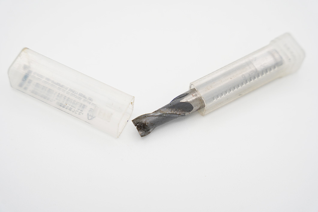
As an easy on-site method, using the plastic cases that came with end mills or drills as tool covers is also a good idea from the standpoint of effective resource use.
Moreover, if you use plastic cases as protective covers, it is effective to define “rules for plastic case colors”—for example, blue for end mills and yellow for drills—so the tool type can be identified by color, and to attach labels indicating size and tool material grade.
If you use transparent plastic cases, you can also identify whether the tool has a coating and the insert grade inside, reducing the need to remove the cover for confirmation.
During Tool Breakage, It’s Not Only Tool Fragments That Can Fly
When a tool breaks due to abnormal load during cutting, it is not only tool fragments that can scatter.
Many machining centers and CNC lathes are designed to protect operators by enclosing the work area with thin steel plates and similar guards to prevent chips and coolant from scattering; however, on general-purpose milling machines and lathes, the rotating tool and work material are often exposed.
As a result, there is a risk that the workpiece being machined may fly toward the operator at high speed at the moment the tool breaks.
Even breakage on the scale of an end mill can sometimes lead to serious injury or accidents, and it is not hard to imagine that the damage becomes even greater if a workpiece in process strikes the body.
In the past, there has also been an accident in which a workpiece came loose from a rotating chuck during machining on a general-purpose lathe, struck an employee working nearby in the lower back, and resulted in hospitalization for several weeks.
While it is important to take good care of tools, forcing the use of worn tools is not recommended from the perspectives of safety and quality. Properly managing tool condition also contributes to managing shop-floor safety.
Always Use Pull Stud Bolts with the Correct Shape for the Machine
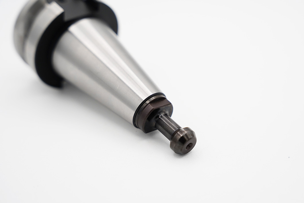
In tool management, attention often tends to focus not only on tool wear and damage but also mainly on tool holder size and rigidity. However, the pull stud bolt used to draw BT or BBT shank tool holders into the spindle also contributes to stable machining and consistent quality.
If you install a pull stud bolt whose shape is “significantly different” from the machine-specified one, it cannot be mounted to the spindle in the first place. However, if the pull stud bolt has a similar shape, it may still mount to the spindle—so caution is required.
If you use it simply because it can be mounted to the spindle, spindle rigidity may decrease, potentially causing poorer surface finish and dimensional accuracy issues.
Moreover, abnormal load is applied inside the spindle, which can damage the tool holder (especially the taper section) and the spindle drawbar that holds the pull stud bolt—so be sure to use the specified pull stud bolt.
In addition, check for looseness of the pull stud bolt installed on the tool holder.
Screws will inevitably loosen over time. Simply confirming that the bolt is tightened before mounting it on a machining center can help prevent the risk of tool drop during machining and abnormal vibration during rotation.
In machining workplaces, tools may inevitably be shared across machines due to reuse of fixed tooling and other reasons. Even in such cases, establish a shop-floor habit of taking the time to replace the pull stud bolt with the specified one.
What Are Metrol’s High-Precision Positioning Sensors?
In real machining environments, you often hear the comment: “No matter how good the tool is, you won’t achieve the target dimensions if tool or workpiece positioning is not precise.” This is why measurement and detection technologies that improve positioning accuracy itself are so important.
Metrol is a manufacturer that provides various sensors focused on positioning accuracy. Here we introduce the key features and use cases of Metrol’s representative high-precision positioning sensors.
High-Precision Positioning Touch Switches
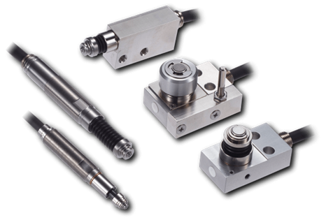
These are contact-type high-precision switches used for positioning and workpiece presence detection in machine tools, robots, and jigs. They achieve an extremely high repeatability of up to 0.5 µm and feature IP67-rated waterproof and dustproof protection, ensuring stable operation even in harsh environments. With more than 200 standard models available, they offer a wide range of variations, including designs for confined spaces, high-temperature environments, vacuum applications, and low contact force requirements.
Tool Setter (Tool Length Measurement Sensor)
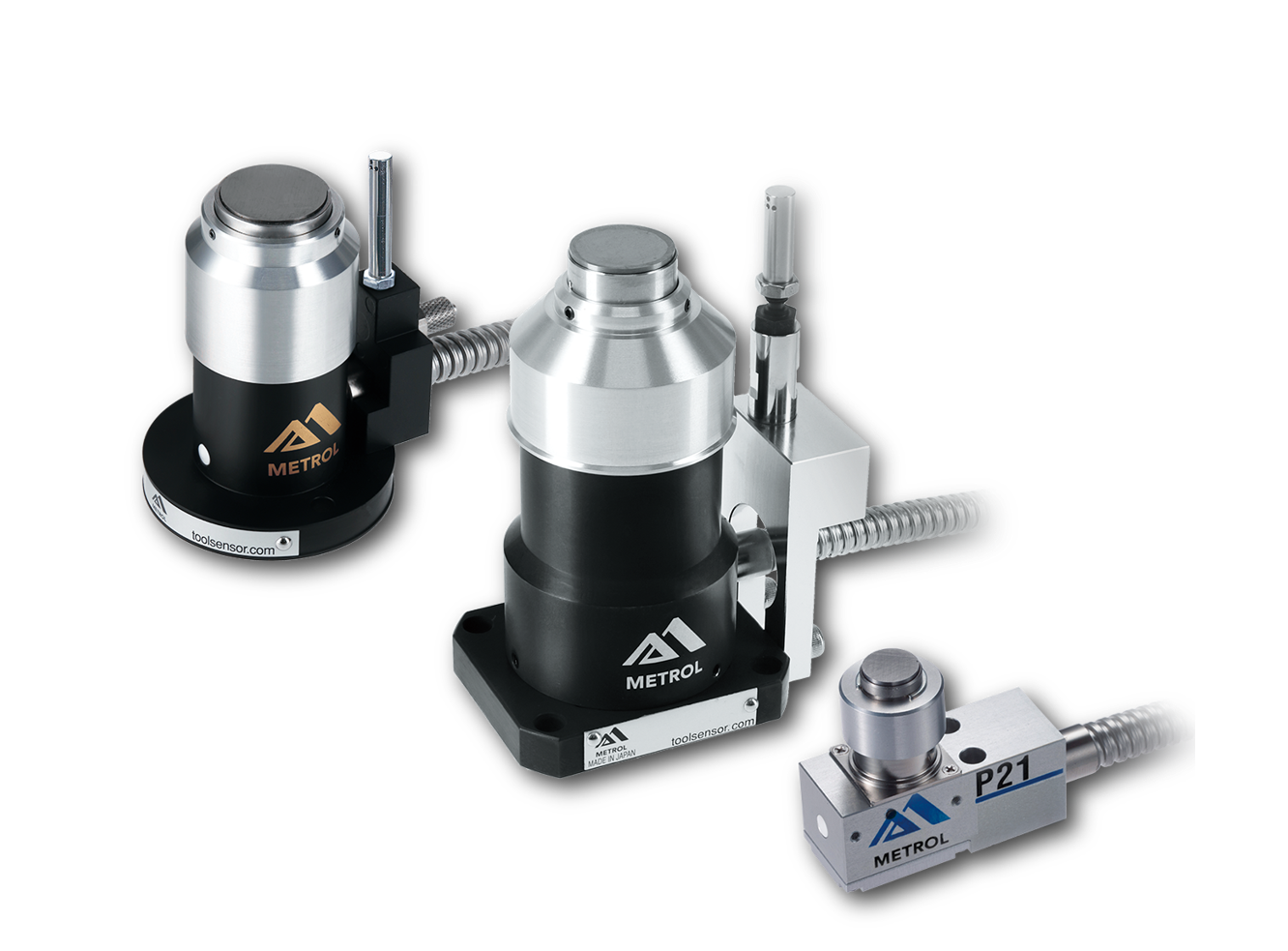
This is a contact-type sensor installed on CNC machine tools and industrial robots for tool length measurement, reference position setting, and tool breakage detection. By automatically measuring and compensating for tool length, wear, and thermal displacement inside the machine, it helps prevent machining defects and significantly reduces setup time. It is one of Metrol’s best-selling products, with a proven track record of more than 500,000 units shipped in 74 countries worldwide.
Touch Probe (On-Machine Measurement Probe)
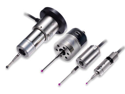
This is a contact-type probe for in-machine measurement, installed on machine tools and robots to automatically perform workpiece positioning (centering) before machining and dimensional measurement after machining. With a repeatability of 1 µm, it automates workpiece referencing and dimensional inspection, replacing skilled manual operations to reduce setup time and help prevent machining defects. Both wired and wireless models are available, meeting retrofit needs for 5-axis machining centers and robotic applications.
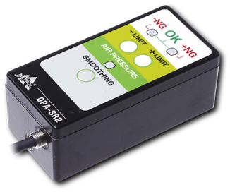
Air Gap Sensor (Pneumatic Sensor)
This is a non-contact sensor that uses air pressure to detect workpiece seating conditions with micron-level accuracy. It can detect gaps (“lift”) of less than 10 µm—previously difficult to measure—with a repeatability of ±0.5 µm, helping prevent machining defects and equipment downtime caused by insufficient contact between the workpiece and fixture. The sensor is used in applications such as semiconductor manufacturing processes, precision part clamping operations, and grinding wheel positioning on grinding machines, and it is a smart sensor that also supports the international standard IO-Link communication.