What Is a Workpiece in Machine Tools? Types, Fixturing Methods, and Practical Design Considerations
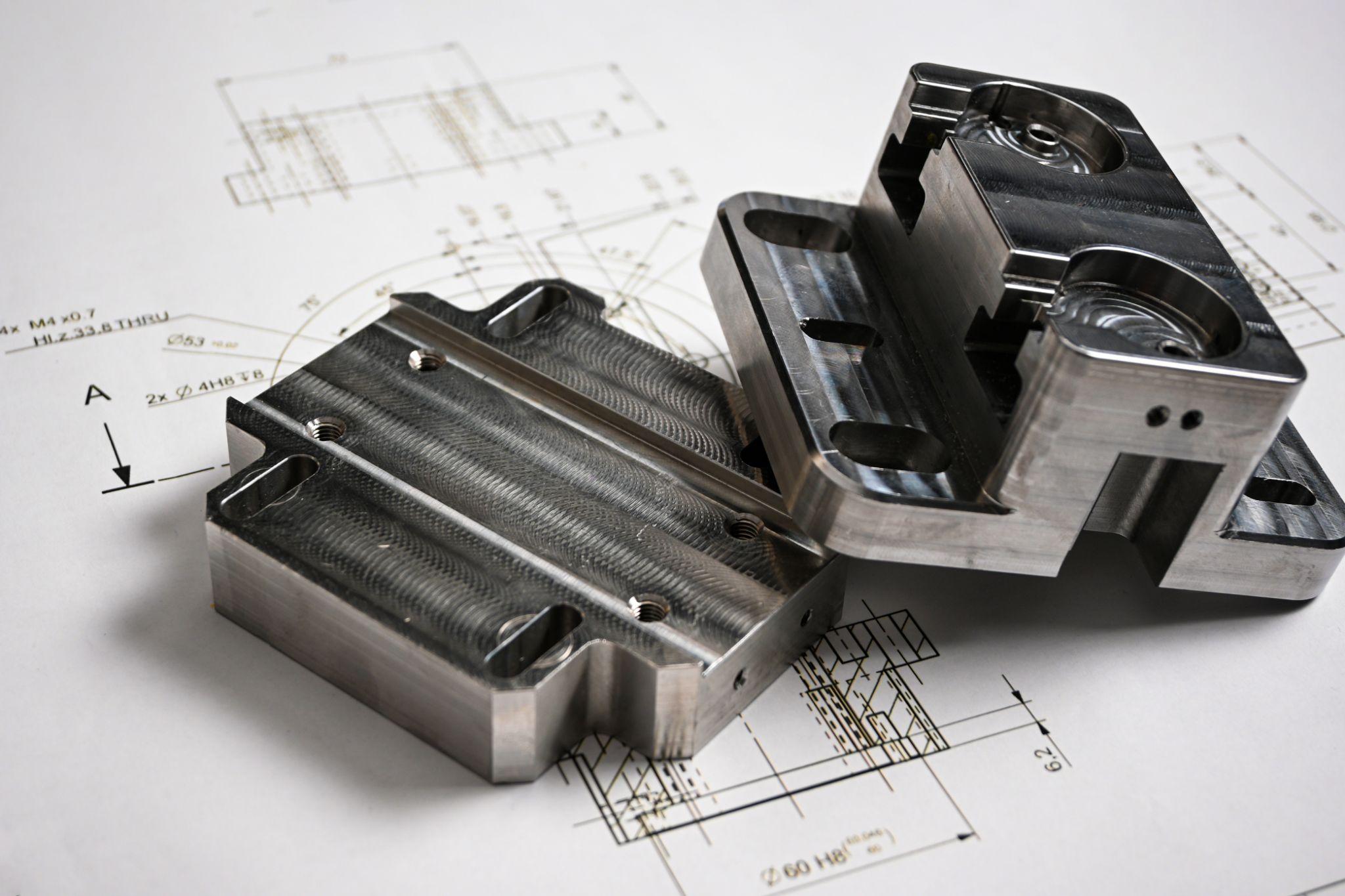
In machining, the workpiece is one of the most critical factors determining product quality and machining accuracy. Differences in material, geometry, and how the workpiece is fixtured can significantly affect both finished accuracy and operational safety.
Moreover, considering “how it will be held” and “how to prevent distortion and thermal deformation” from the design stage directly leads to high-precision and efficient manufacturing.
This article explains the definition and types of workpieces, why workholding matters, how it affects machining accuracy and safety, and key design considerations. It also introduces real-world countermeasures used on the shop floor and practical ways to leverage high-precision sensors.
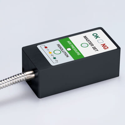
High-precision seating confirmation of workpiece and jig
- Air Gap Sensor -
You can check not only "presence/absence" but also "adhesion (gap)" at the same time with a repeatability of ±0.5 μm.
Click here ›Table of Contents
Definition of a Workpiece and Its Basic Role
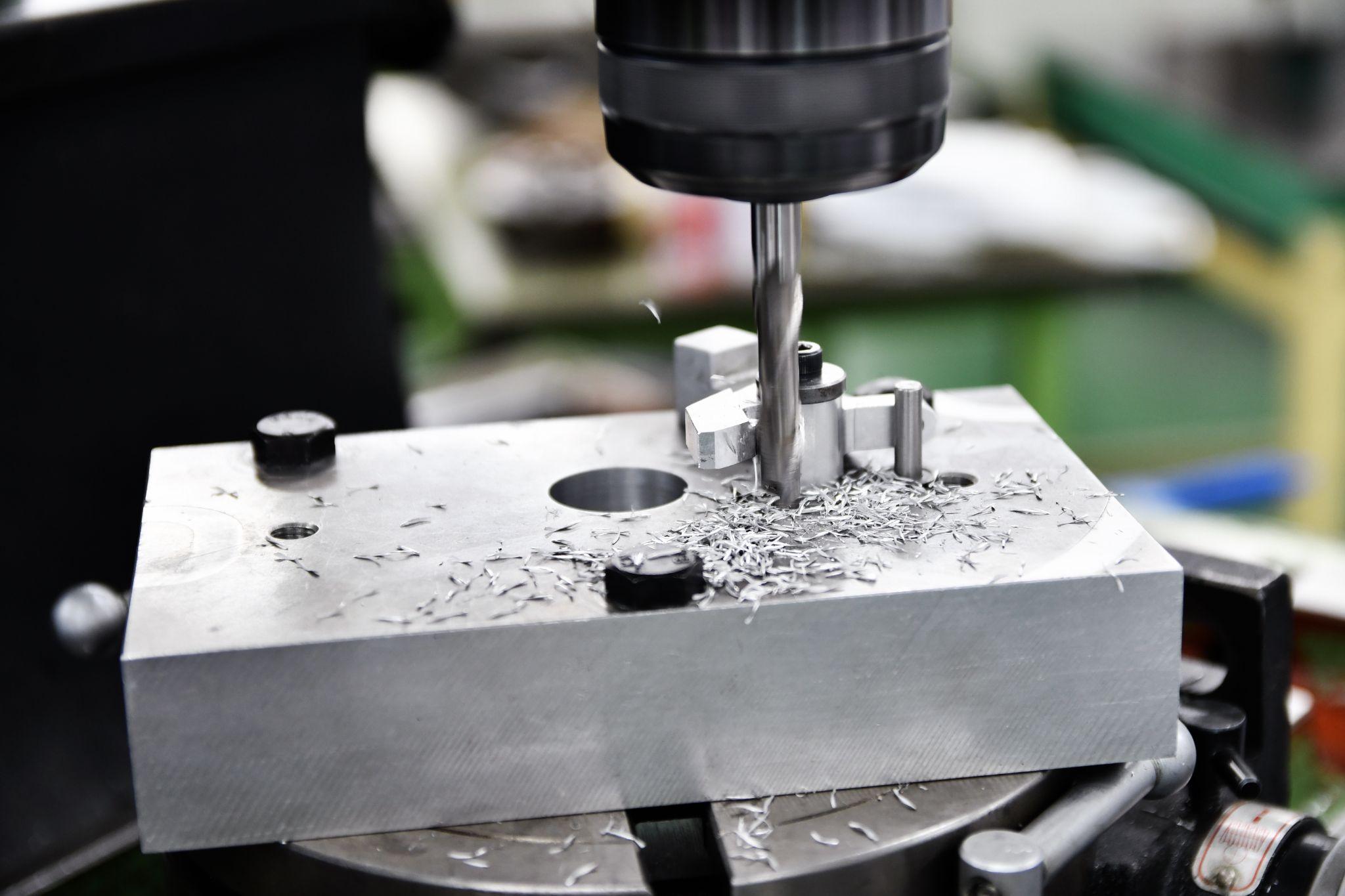
In machine tools, a workpiece refers to the object being processed through operations such as cutting or grinding.
In general, a workpiece is the raw material or component that will be machined into the final product shape—an “object to be processed” that is cut from stock such as metal blocks or plate material into the required geometry.
In a machine tool, the workpiece is the counterpart to the cutting tool, and the machine is always equipped with a mechanism to fixture and hold the workpiece while controlling its relative motion to the tool.
In other words, the workpiece is the “main actor” whose shape is changed by the machine tool. The machine creates highly accurate dimensions and geometry by holding the workpiece at a specified position and moving the tool accordingly.
The role of the workpiece is, quite literally, to be processed—gaining added value through tooling actions and becoming the final product.
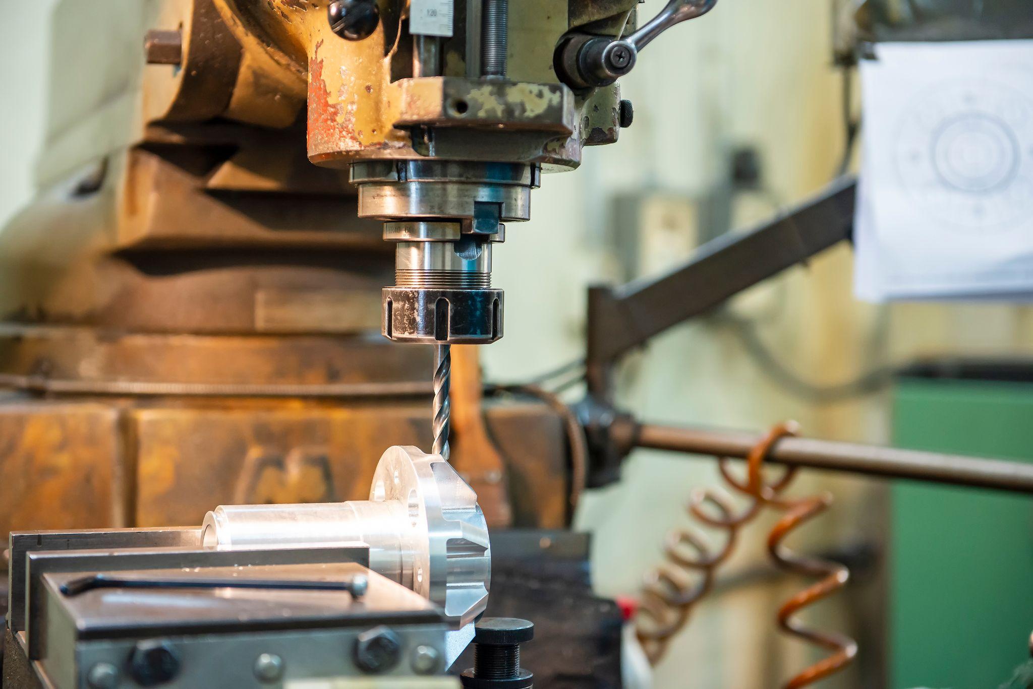
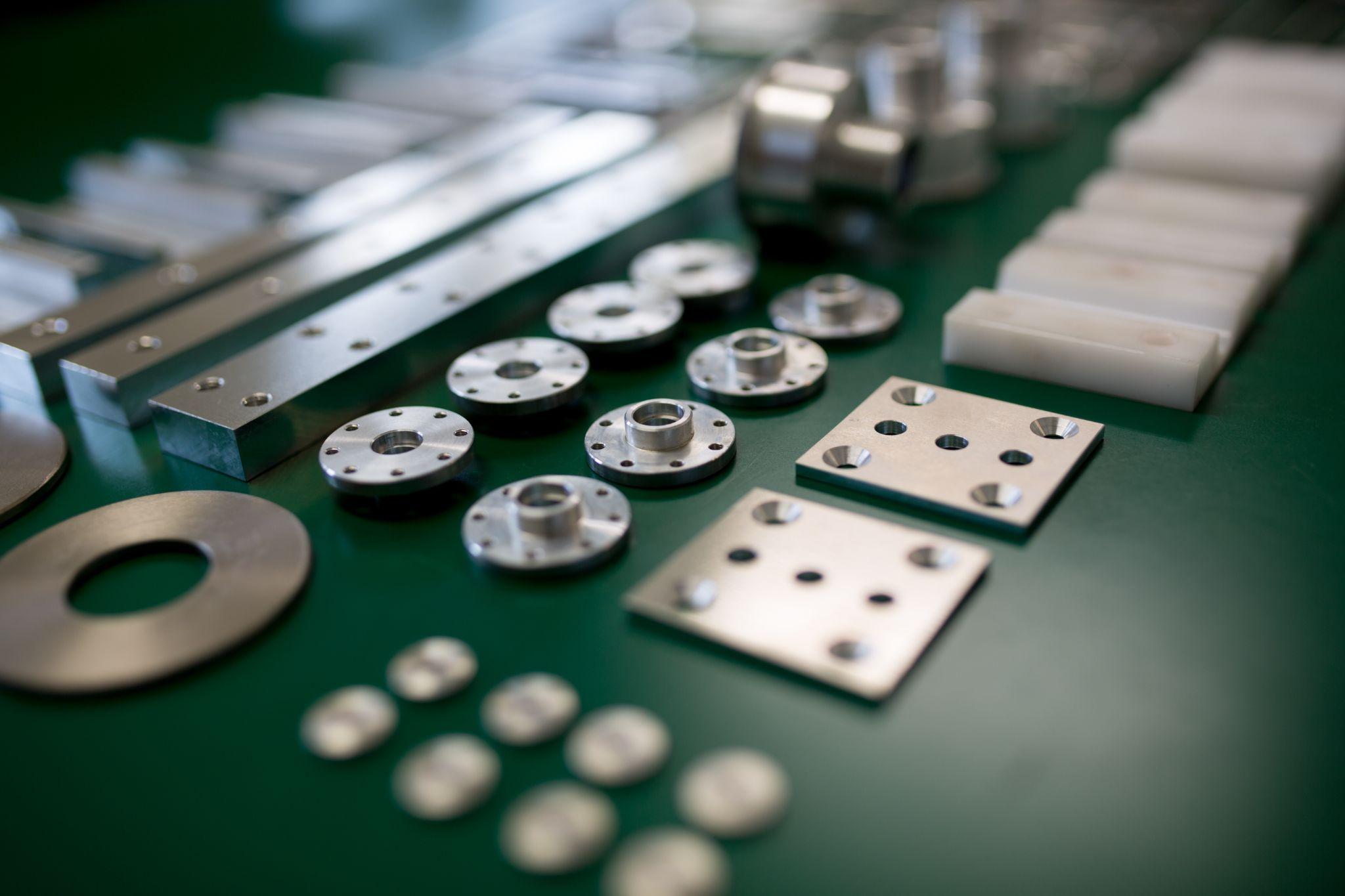
Types of Workpieces (Materials, Shapes, and More)
Workpieces come in a wide range of materials and shapes.
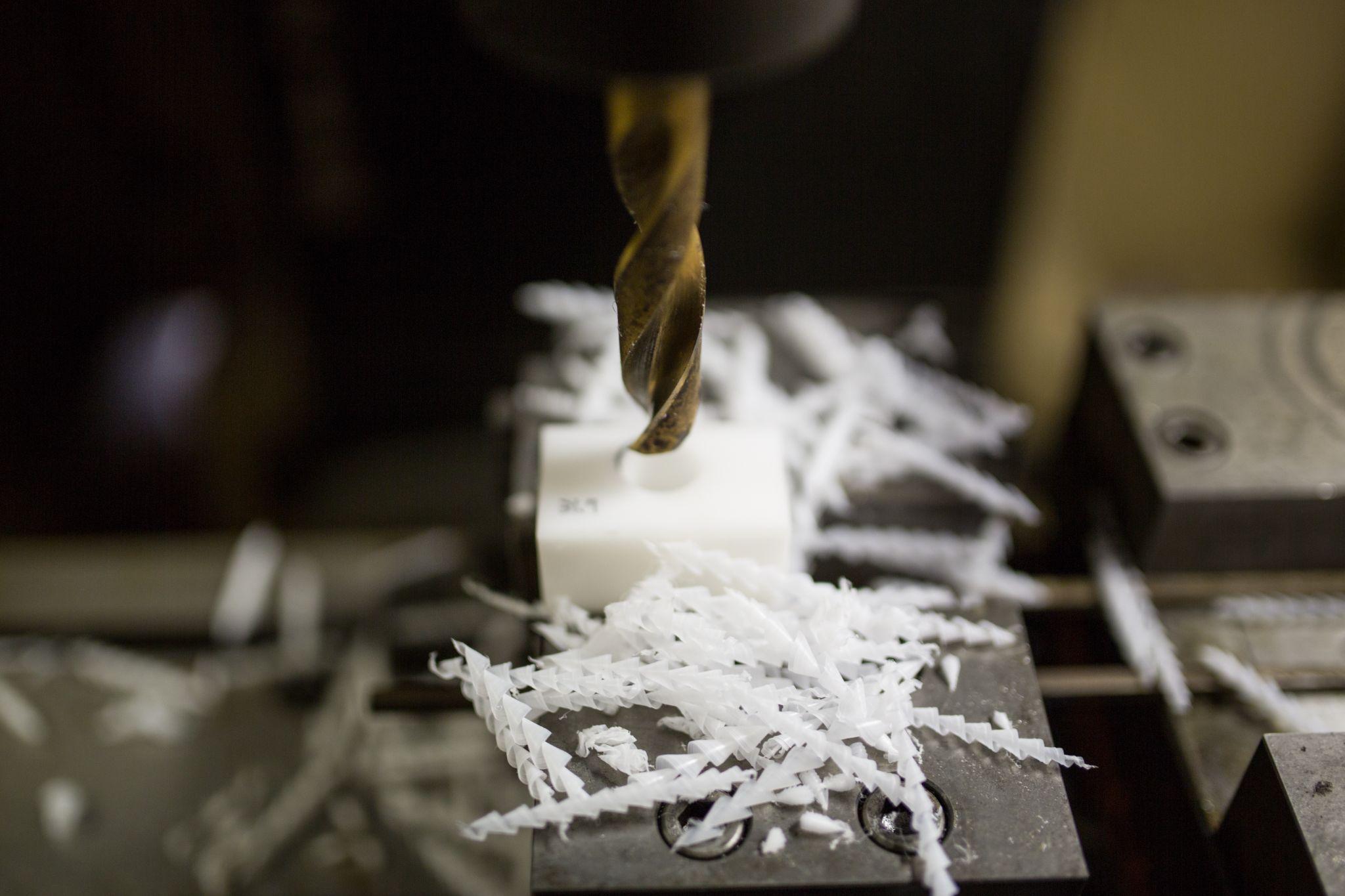
Machine tools primarily process metal materials (such as steel, aluminum, and copper alloys), but depending on requirements, plastics/resins and even carbon fiber composites may also be machined.
Even among metals, materials differ in machinability and strength—such as cast iron, stainless steel, and titanium alloys—each requiring appropriate tooling and machining conditions.
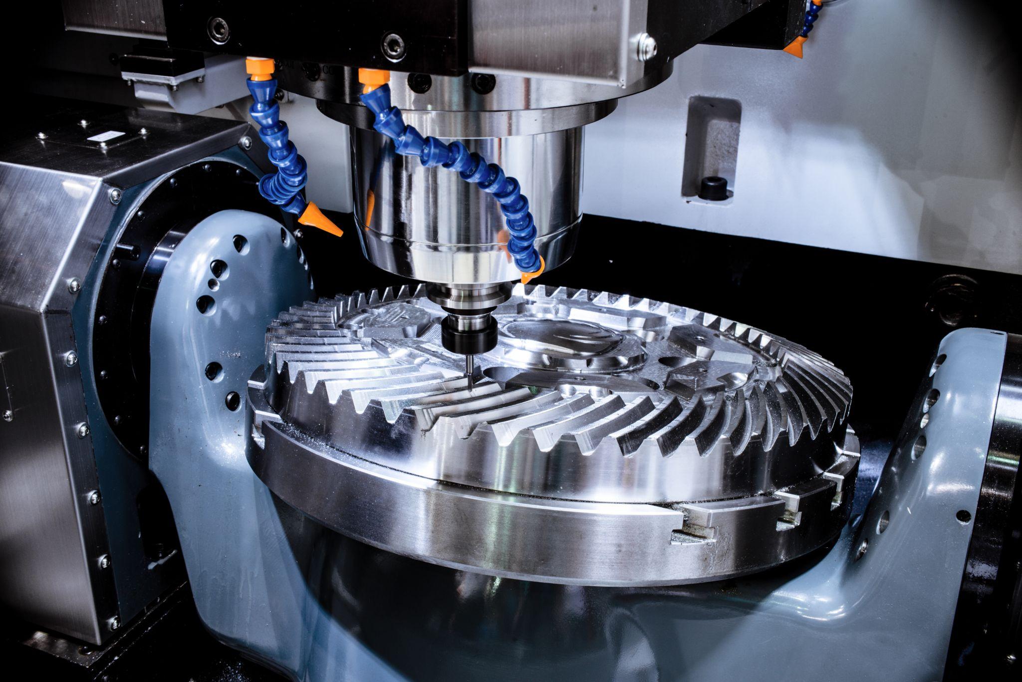
Workpiece geometry also varies widely. Flat workpieces (plate stock or block material) machined on milling machines typically need stable fixturing using a vise, a T-slot table, a vacuum chuck, or similar methods.
Cylindrical or rotationally symmetric workpieces (shafts or cylindrical parts) are mainly turned on lathes. They are firmly gripped with a chuck or collet chuck, and supported with a center or other supports as needed.
For irregular or complex workpieces—such as cast or forged automotive parts—standard fixtures may not hold them well, so dedicated fixtures or modular fixturing systems are used to secure them reliably.
Depending on the case, vacuum suction or a magnetic chuck may also be used. Select an appropriate workholding method based on the workpiece geometry and material.
Workholding Methods and Why They Matter

When machining a workpiece on a machine tool, workholding is a critically important factor.
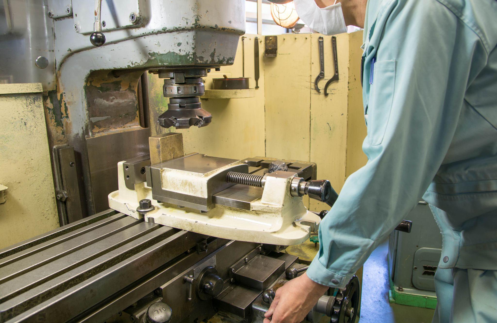
Common workholding devices include vises for milling machines and machining centers; chucks for lathes (such as scroll chucks and collet chucks); various clamps (toggle clamps, T-slot nuts and bolts, fixture clamps, etc.); and dedicated holding devices called fixtures.
These workholding devices are mounted to the machine so that the workpiece remains stable in the intended position without micro-movement or vibration during machining.
Properly securing the workpiece is absolutely essential for both machining accuracy and safe operations.
If a workpiece is not firmly secured, cutting forces and machine vibration can cause it to shift or come loose during machining. This not only creates dimensional errors but can also lead to tool breakage and machine accidents.
For example, incorrect selection or use of clamps or vises can leave the workpiece unstable, causing unexpected movement, ejection, or detachment during machining—potentially resulting in serious accidents or injury.
On the other hand, excessive clamping is also problematic. Applying more clamping force than necessary can crush or distort the material, leading to accuracy issues or surface damage (clamp marks) after machining.
Therefore, it is important to choose a workholding method suited to the workpiece shape, size, material, and machining operation—and to clamp with sufficient holding force applied evenly.
In fixture design, stable holding is achieved through both locating and clamping, helping suppress vibration and ensure repeatability during machining.
Proper workholding forms the foundation of machining accuracy and is also a key pillar of safety.
High-precision seating confirmation of workpiece and jig
- Air Gap Sensor -
You can check not only "presence/absence" but also "adhesion (gap)" at the same time with a repeatability of ±0.5 μm.
Click here ›Impact on Machining Accuracy and Safety
The quality of workholding directly affects both machining accuracy and safety.
From an accuracy standpoint, insufficiently secured workpieces can shift or vibrate under cutting forces, making it impossible to achieve the intended dimensions or surface finish.
If the workpiece deflects under tool pressure, dimensions can deviate significantly and surface roughness can worsen.
If the workpiece itself has low rigidity, poor clamping can cause distortion or deformation during machining, leading to warpage or mislocated holes after processing.
For thin-walled parts, clamping stress can degrade flatness and cause bolt-hole locations to deviate from the design dimensions.
In this way, improper clamping leads to defects in finished dimensions and geometric accuracy.
From a safety standpoint, insufficient clamping increases the risk of the workpiece coming loose and being ejected during machining, which can cause major accidents.
If a high-speed rotating workpiece comes off, it poses a serious hazard to nearby personnel and can also damage the machine tool and cutting tools. In shop-floor safety rules, securing the workpiece is one of the most critical requirements.
At the same time, it is important to watch for negative effects of clamping—namely, damage caused by the clamps themselves.
As mentioned earlier, beyond deformation from over-tightening, direct contact with hard vise jaws or clamps can leave scratches or indentations (clamp marks) on the surface.
This can lead to cosmetic defects or functional problems (such as poor mating contact), so clamping on finished surfaces requires extreme care.
Because workholding has a major impact on both machining results and shop-floor safety, it is essential to continually evaluate optimal fixtures and holding methods and operate them properly.
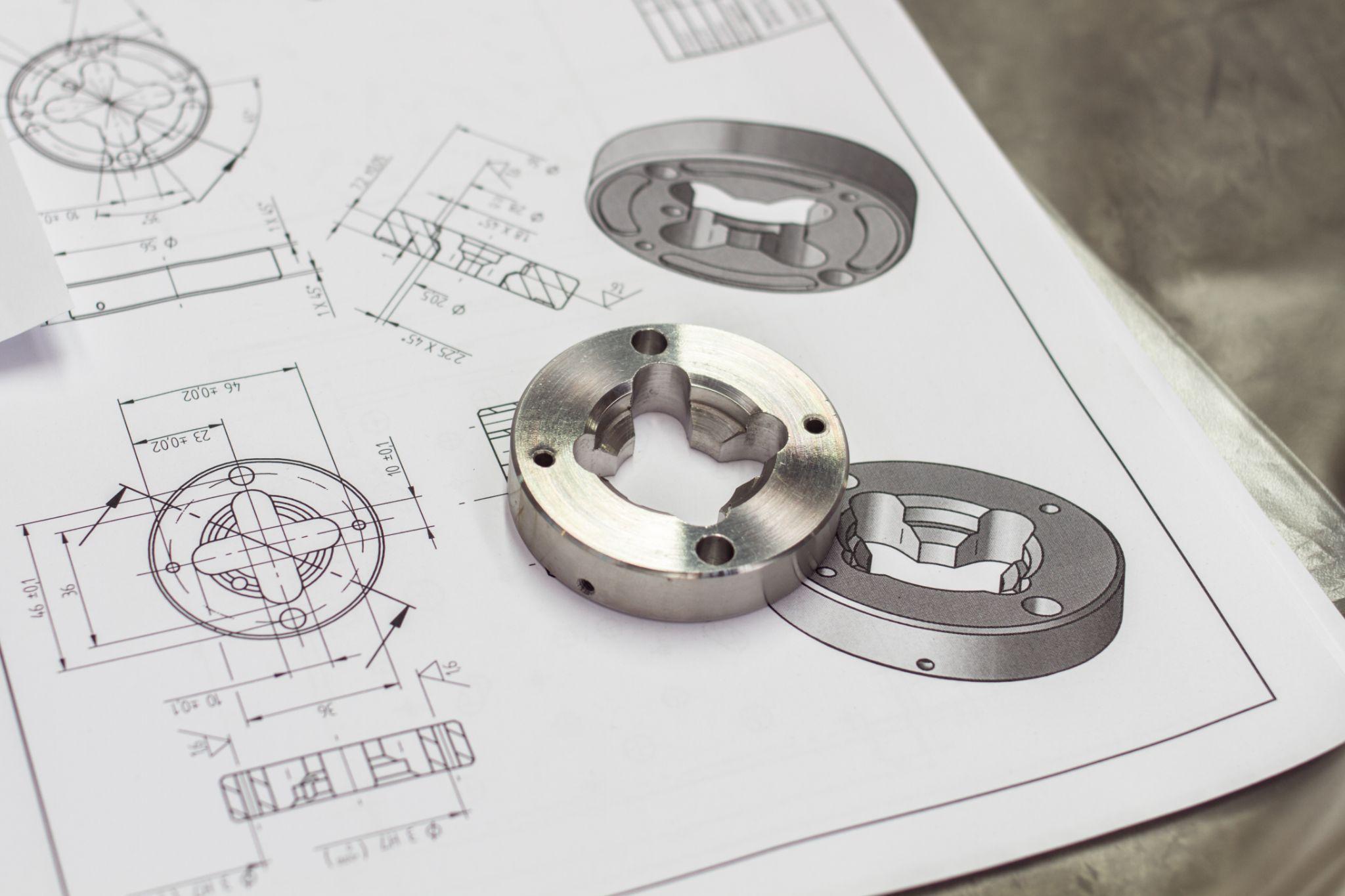
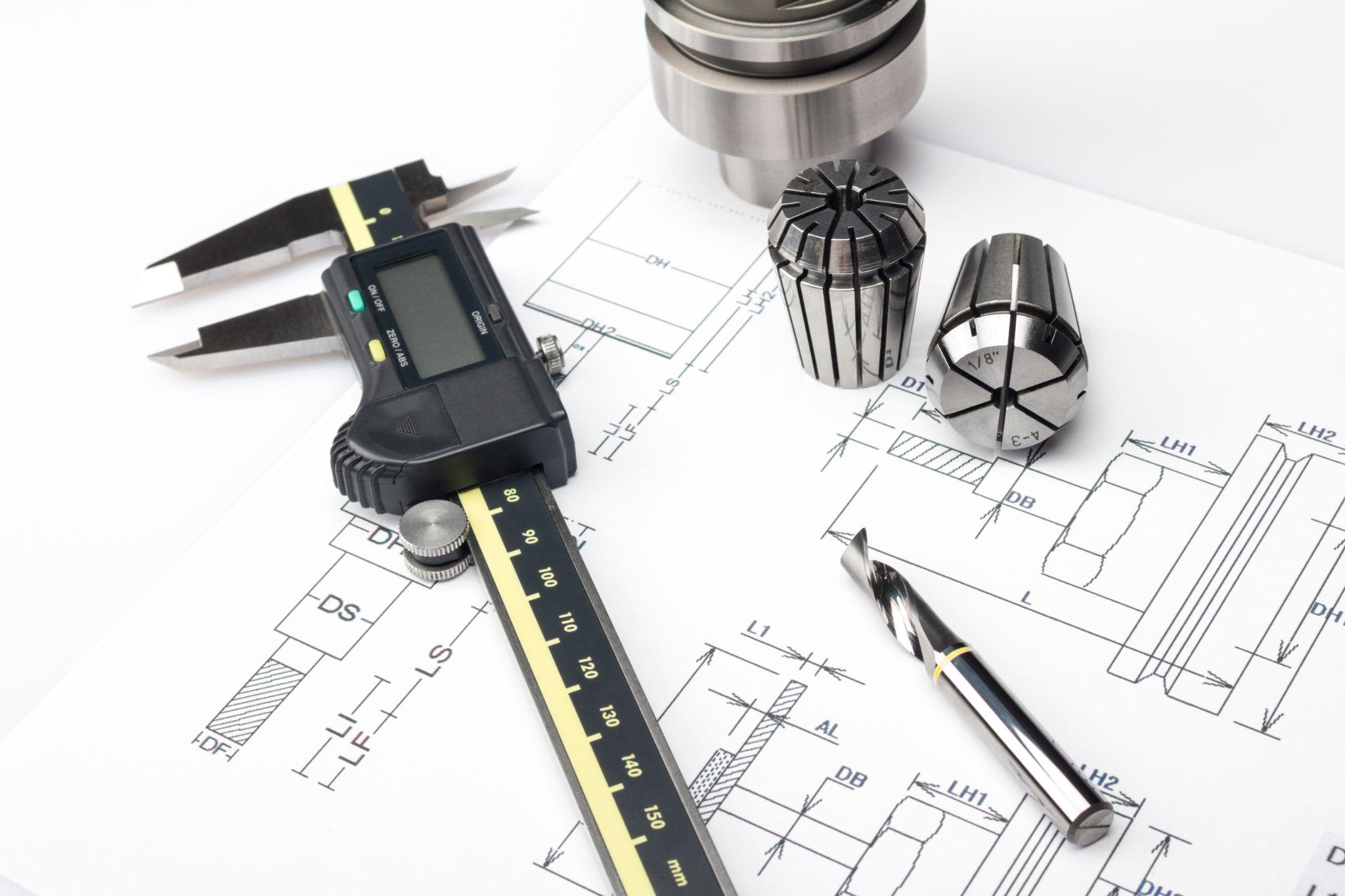
Design Considerations for Workpieces
From the workpiece (part) design stage, it is important to consider various factors so it can be finished to high quality without issues on the shop floor.
Below are key points designers should keep in mind when workpieces will be machined on machine tools.
Optimizing Machining Direction and Machining Sequence
Depending on part geometry, accuracy and distortion can vary greatly based on machining direction and the order in which material is removed.
For example, in thin-walled box-shaped parts, removing a large amount of material from one side in a single direction can cause the opposite face to warp.
Therefore, it is important to plan a machining sequence that removes material symmetrically to reduce stress imbalance.
In practice, precision thin-walled parts often use symmetric machining—alternating removal on left/right and front/back surfaces—to equalize tensile stress and prevent post-machining warpage while maintaining flatness.
If a large amount is removed from only one side at once, the stress balance can collapse and distortion becomes more likely. The key is to separate roughing and finishing and remove material step-by-step and evenly.
Regarding machining direction, it is also worth considering workpiece orientation and support methods at the design stage—for example, keeping the datum surface on the bottom to maintain rigidity, or placing long parts horizontally rather than vertically to reduce deflection.
Countermeasures Against Distortion and Deformation
Workpiece materials can experience distortion and dimensional changes due to the release of internal stress during machining and due to cutting heat.
For that reason, designs should incorporate measures to address expected distortion from the outset.
For example, when thick and thin sections coexist, distortion is more likely due to stress concentration from thickness differences. Depending on the case, stress-relief annealing may be performed mid-process, or the part may be rough-machined first, allowed to “move” naturally, and then finished in a later step.
Even at the material selection stage, distortion resistance can be considered by using stabilized, heat-treated stock or choosing materials with low residual stress.
It is also important to watch for elastic deformation caused by clamping.
Thin or slender workpieces can deflect easily during clamping, so it can be effective to add ribs or reinforcement for rigidity, or to design temporary “tabs” or bridging material used only during machining and removed afterward.
In addition, ensure that datum surfaces and datum holes used as design references are not lost due to distortion or machining allowance during processing.
For example, machine datum surfaces as early as possible and preserve them through later steps, or optimize clamping positions so the datum does not shift during machining.
If a datum surface warps or is machined away mid-process, locating repeatability is lost in subsequent steps and accuracy suffers. Designing with a machining sequence and fixtures that protect the datum is therefore crucial.
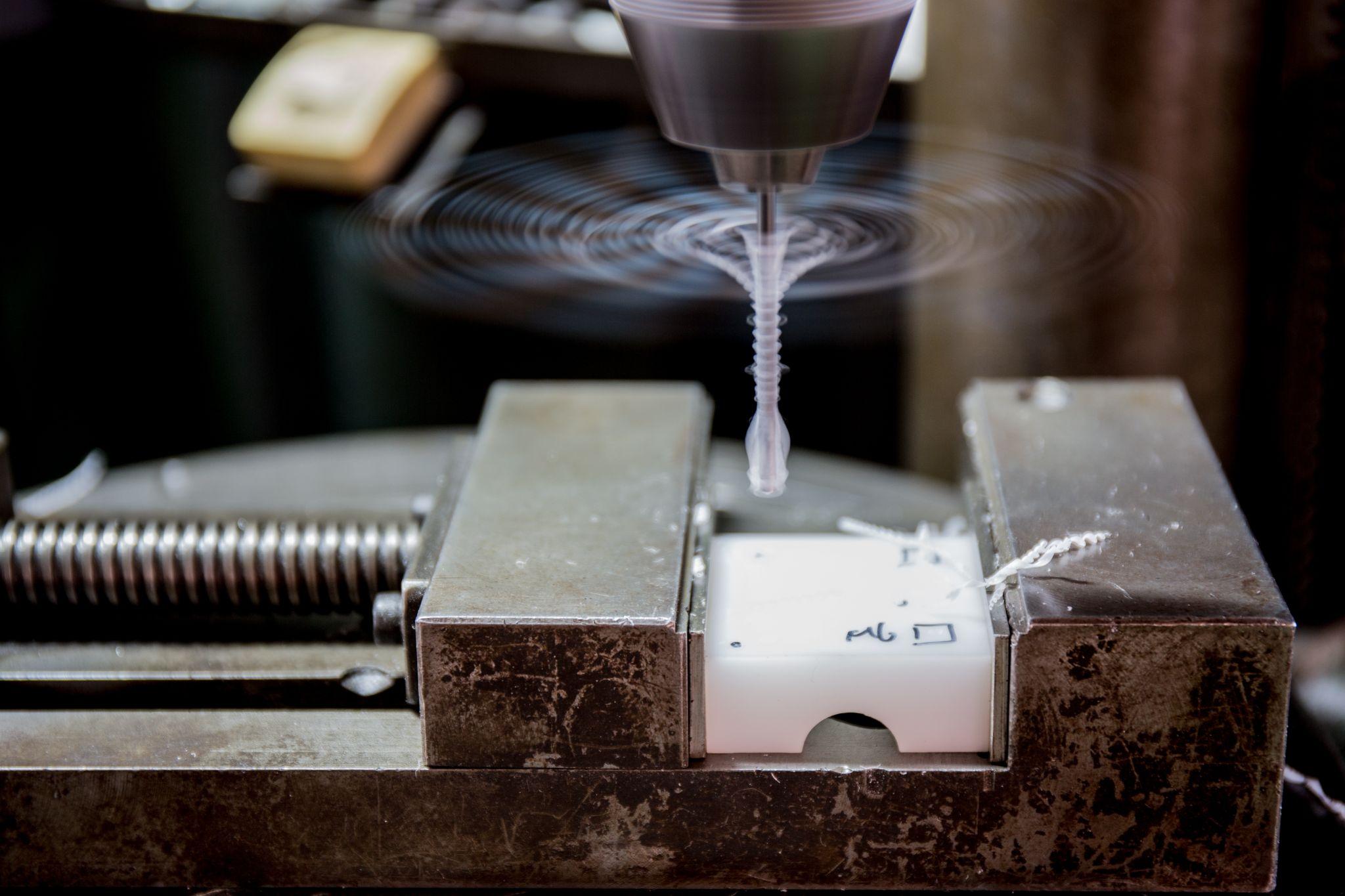
Thermal Deformation and Countermeasures
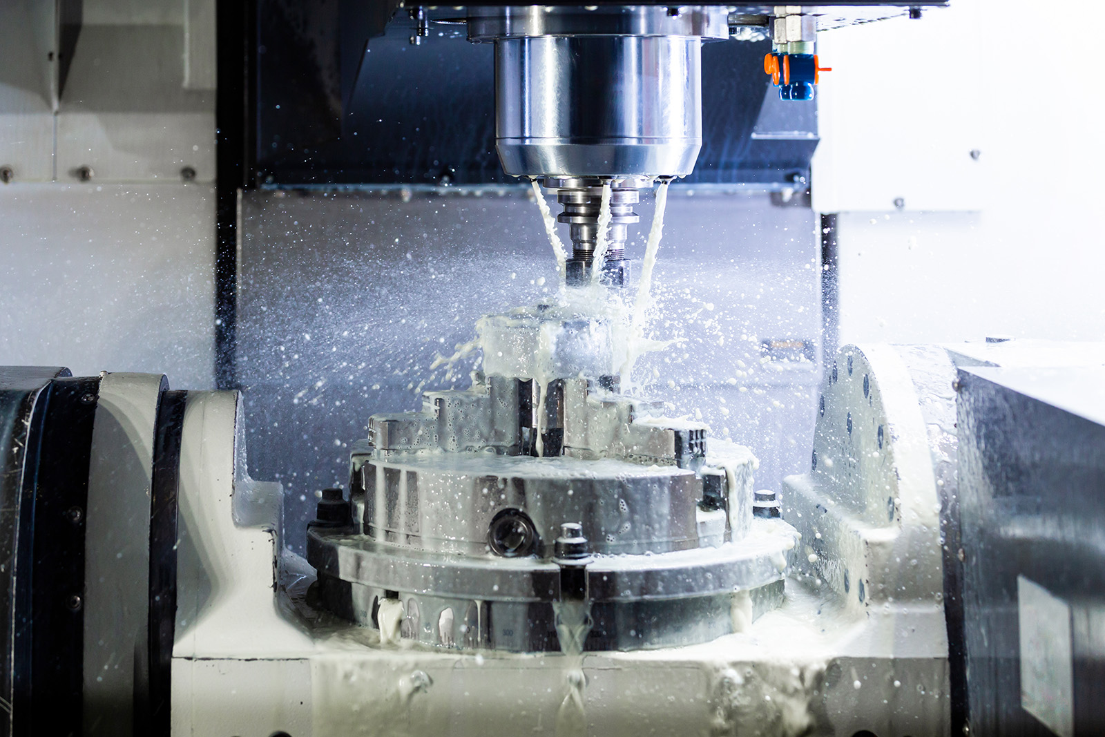
In cutting and grinding, heat is generated at the machining point, and the workpiece may undergo dimensional changes due to thermal expansion.
Especially in long continuous machining or high-speed cutting, workpiece temperature can rise. A part may be expanded and appear within tolerance during machining, then shrink as it cools and fall out of tolerance.
Designers should also take a viewpoint that minimizes the influence of machining heat.
For example, allow sufficient access for coolant in the geometry, and for materials prone to thermal deformation (such as plastics), plan for staged machining—roughing → cooling → finishing—rather than completing everything in one pass.
For large parts, the entire workpiece may expand due to machining heat, so critical dimensions may be left slightly oversized and then finish-machined after returning to ambient temperature.
Also consider that coefficients of thermal expansion vary by material. When high precision is required, it may be worth selecting low-expansion alloys or designing under the assumption of temperature-controlled machining (such as in a constant-temperature room or with preheating).
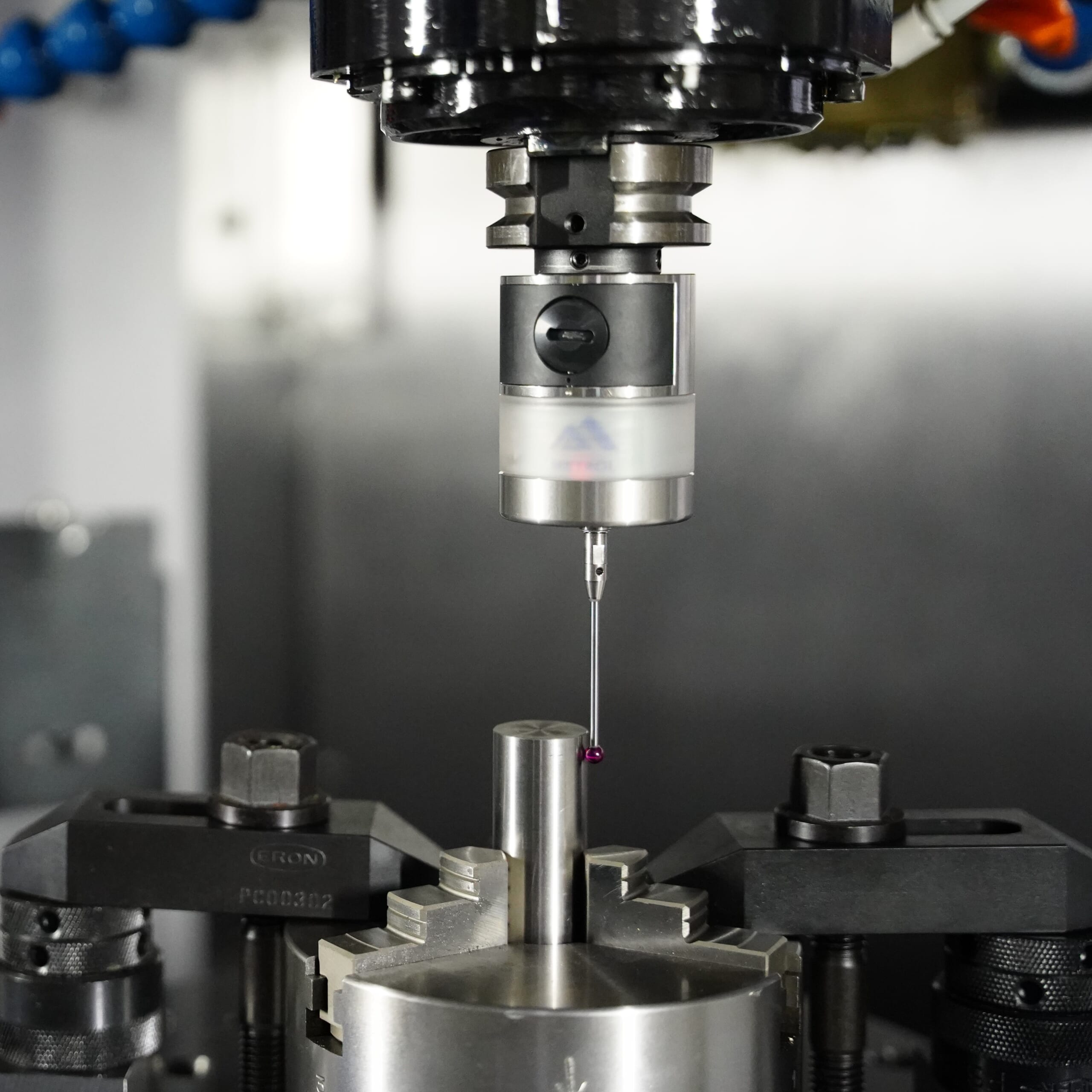
Automated workpiece centering and positioning
- Touch probe -
A contact/touch sensor for on-machine measurement that improves the efficiency of setup work
Click here ›Preventing Clamp Marks and Protecting Surface Finish

When designing a workpiece, take care that areas contacted by clamps or fixtures during machining are not critical product surfaces.
If a critical surface must be clamped, plan a process that includes extra stock for finishing so the surface can be lightly re-finished at the end.
Directly clamping with hard chuck jaws or clamps can leave dents or scratches due to metal-to-metal contact. Consider providing space for protective shims in the design, and allow the fixture to use soft resin pads or soft-metal jaws.
For soft materials such as aluminum or copper, using aluminum soft jaws instead of steel vise jaws can prevent the surface from being gouged.
For areas where appearance matters, avoid clamping whenever possible. If clamping is unavoidable, clamp in hidden areas or design the fixture with precise contact surfaces that match the workpiece so it is held by surface contact rather than point contact, preventing localized pressure concentration.
Clamp marks are often overlooked, but they directly affect finish quality and product value—making them an important point to address during design.
Designing with Fixtures and Setup in Mind
Product designers need to be mindful of how the parts they design will be set up and machined on the shop floor.
For example, adding lifting holes or handling features can make it easier to set large workpieces into fixtures using a crane.
Other measures include providing fixture holes for intermediate support on long parts, or incorporating center holes in rotationally symmetric parts so they can be machined with support at both ends.
For parts requiring multi-face machining in a single setup, providing a fixture mounting/datum surface on the part (for example, using one face of a square block as a datum to press against and clamp) can improve repeatable positioning accuracy and simplify setup.
In short, work backward from the question, “How can this workpiece be held stably?” and incorporate shapes and additional features that make fixture design and setup easier.
This also improves communication with machinists and fixture designers, ultimately boosting machining accuracy and productivity.
Practical Perspectives and Tips for Product Designers
Finally, from the perspective of experienced manufacturing designers, here are important ideas and practical tips for workpiece design and machining preparation.
Keeping the following points in mind helps designers collaborate smoothly with the machining floor and greatly improves both quality and productivity.
Design for Manufacturing (DFM): Designing with Machining in Mind
When designing parts, it is important to envision actual machining methods and sequences and create shapes that are manufacturable.
For example, consider questions such as “This pocket is very narrow and deep—can the tool reach?” or “Can this threaded hole be machined later?” and revise the design as needed.
It is also effective to consult early with shop-floor engineers and skilled machinists to obtain feedback for more machinable designs and appropriate tolerance settings.
As a result, this reduces machining issues and rework, shortens lead times, and lowers costs.
Securing Clamping Areas and Fixture Reference Features
Designers need to be aware of where the part will be clamped and secured during machining.
For example, if every outer surface is a machined surface, there may be no place left to clamp.
To address this, designers may intentionally add extra features for clamping in fixtures (such as flanges, handle-like protrusions, or lifting holes).
If those features are designed to be removable after machining, they can be used for stable holding during processing and then cut off afterward.
For complex-shaped parts, providing at least one flat, rigid datum surface can make setup easier, since the part can be pressed against that surface and secured in the fixture.
In short, anticipate how the part will actually be fixtured, and ensure the geometry includes clamp-friendly features and sufficient clamping allowance.
This improves clamping stability, which in turn increases machining accuracy.
High-precision seating confirmation of workpiece and jig
- Air Gap Sensor -
You can check not only "presence/absence" but also "adhesion (gap)" at the same time with a repeatability of ±0.5 μm.
Click here ›Balancing Tolerances and Finish Requirements
In design, it is not always best to make every dimension strict. Instead, specify tight tolerances and surface finish requirements only for critical dimensions and surfaces, and relax requirements elsewhere where feasible.
On the shop floor, unnecessarily tight tolerances and finish requirements increase machining time and drive up costs.
Designers should identify which dimensions truly matter and apply clear prioritization—for example, allowing slightly rougher results where function is not affected.
If meeting requirements in a single step is difficult, it can also be effective to specify the machining process in advance, such as “rough machining → grinding finish” for a surface, or “reamer finish” for a hole.
By aligning with the shop floor and optimizing tolerances, productivity can be improved while maintaining product quality.
Material Selection and Pre-Treatment
Selecting the workpiece material directly impacts machinability and finished quality.
For example, high-hardness materials accelerate tool wear and increase machining time, so designers should consider whether that hardness is truly necessary.
Conversely, materials that are too soft may be easy to machine but lack strength, so plan the process with heat treatment in mind.
Materials with high internal stress (such as rolled stock or welded structures) tend to distort after machining. Plan pre-treatments at the design stage—for example, performing a stress-relief heat treatment beforehand, or for large stock, roughing first, allowing it to cool and settle naturally, and then finishing.
Also consider variability among material lots. If needed, change suppliers or review mill test certificates and analysis reports to select materials with stable machinability.
Coordination with Process Planning
Excellent product designers take a broad view—not only of individual part design, but of the entire manufacturing process.
During the design stage, it is advisable to meet with process owners and share the optimal machining sequence, fixture concept, and even the inspection plan.
For example, note information such as “This area is finished last, so the datum is here,” or “This goes to grinding, so leave a 0.2 mm margin,” on process sheets or drawings.
This enables the shop floor to machine with clear design intent, reducing rework.
Actively clarify unclear points by consulting the shop floor, and carefully document key notes in drawing remarks or as annotations on 3D models.
With close communication between design and manufacturing, feedback moves quickly when issues arise, making it easier to sustain cycles of design and process improvement.
Ultimately, this strengthens manufacturing competitiveness through higher quality and improved mass-production capability.
Automated workpiece centering and positioning
- Touch probe -
A contact/touch sensor for on-machine measurement that improves the efficiency of setup work
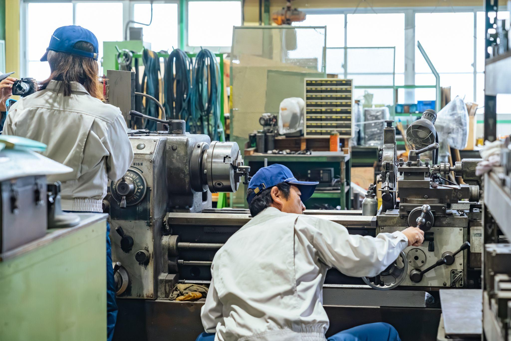
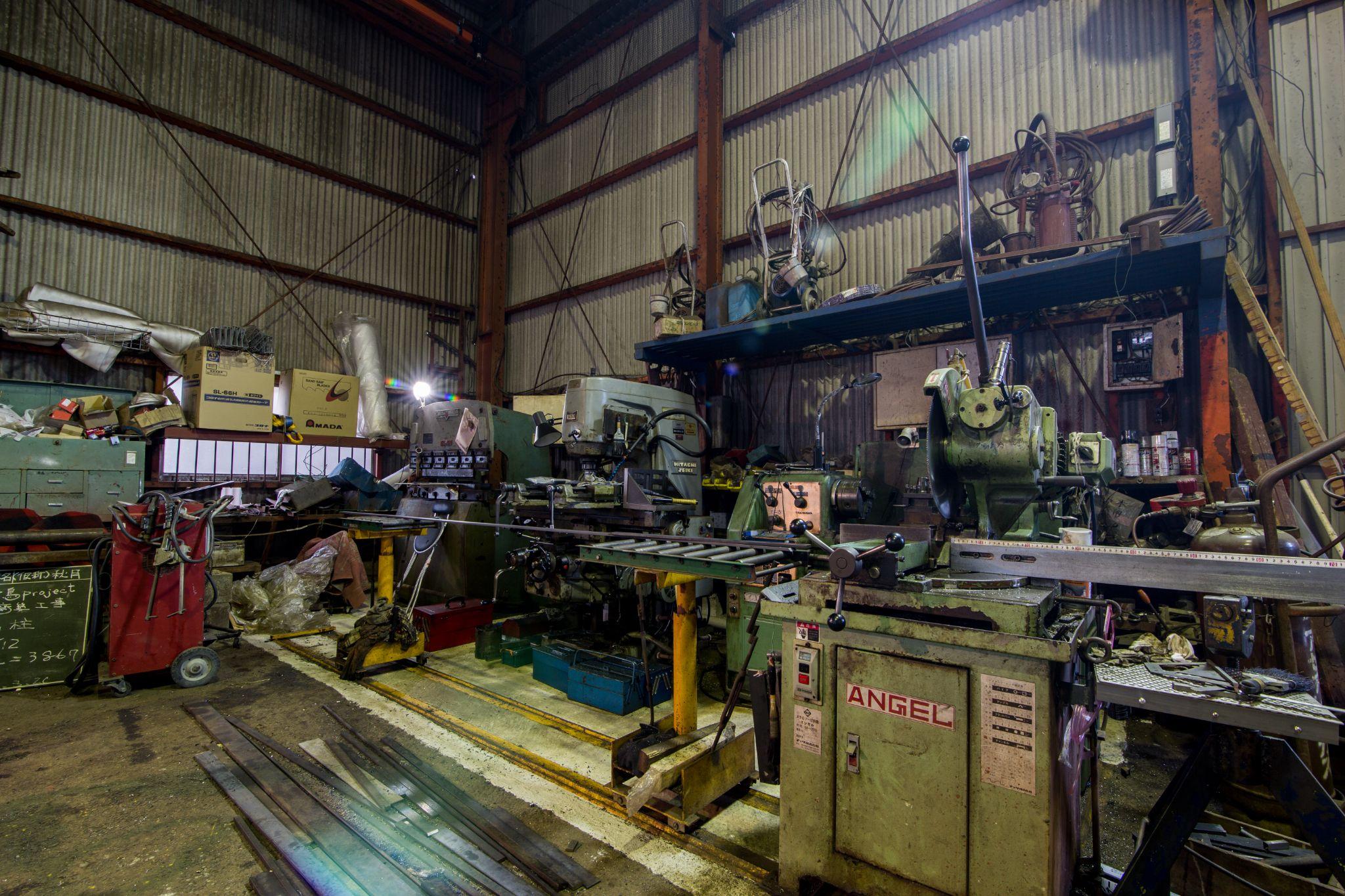
Click here ›Real-World Countermeasures for Workpiece Handling on the Shop Floor
On machining floors, products made from a wide range of materials—iron, stainless steel, aluminum, copper, brass, and more—are processed daily to meet customer requirements.
Based on actual complaints and rework cases, we introduce below examples of countermeasures adopted to avoid scratching workpiece surfaces.
How We Eliminated “Imprint Marks” Caused by Vise Jaws
When clamping workpieces made of resin or aluminum in a vise, “round imprint marks” may appear on the surface even if the vise is not tightened excessively.
These are imprint marks caused by the bolt holes (counterbored holes) used to secure the vise jaws, and they tend to occur when a leveling block is placed under the workpiece so the workpiece sits higher than the jaw height.

As shown above, the leveling block raises the workpiece, concentrating pressure on the counterbored holes of the bolts that secure the vise jaw, which creates round imprint marks.
This occurs especially often with materials such as aluminum, and for appearance-critical products it may be treated as a defect.
If the imprinted surface later becomes a datum surface, the deformation caused by the counterbore imprint may prevent achieving the required machining accuracy.
As a countermeasure, this issue was resolved by inserting a leveling block of the same height as the jaw between the jaw and the workpiece.
It is advisable to prepare this block separately from the blocks typically used for raising workpieces.
Keeping Clamping Pressure Consistent During Machining Center Operations
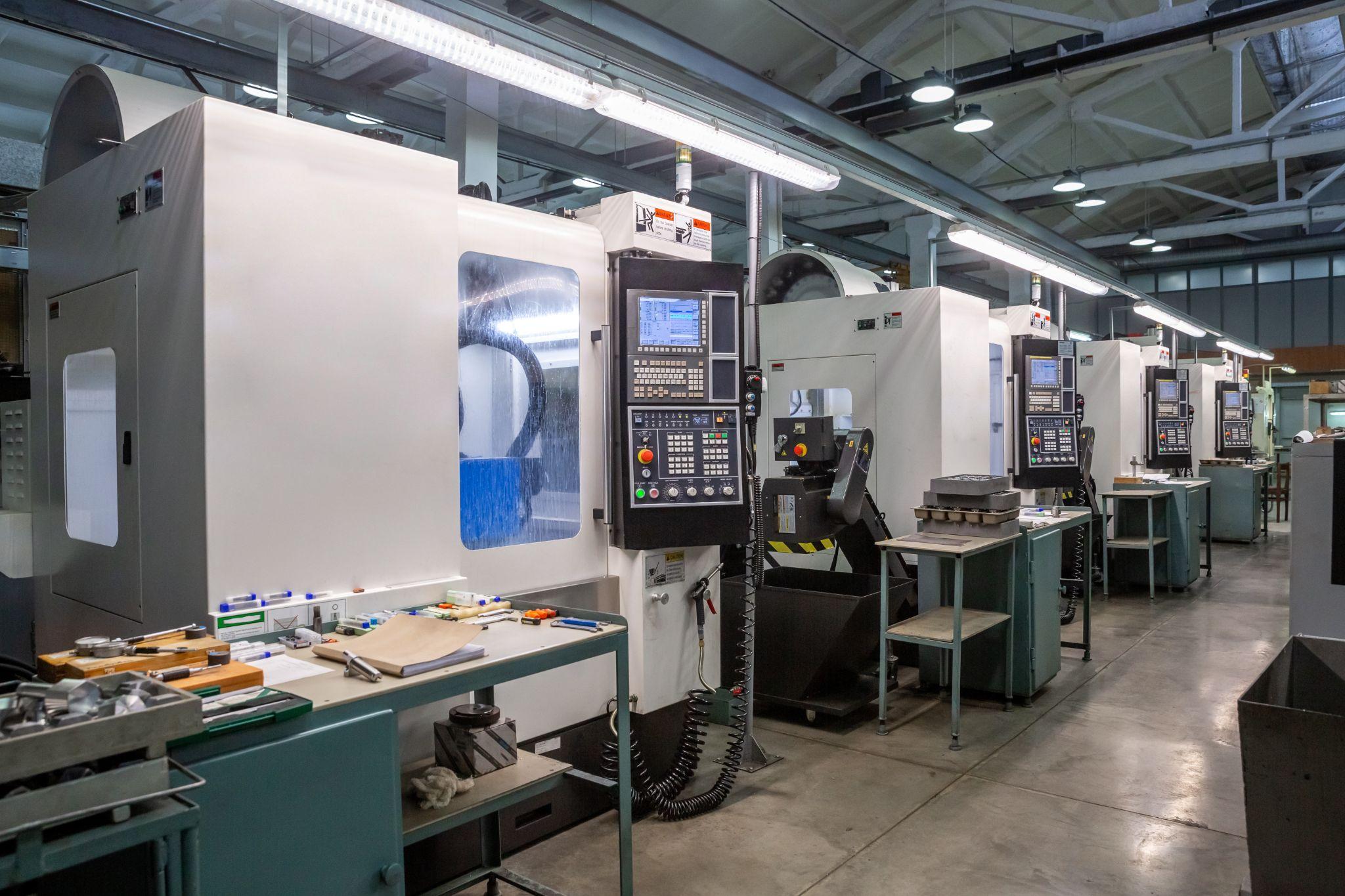
Machining center operations are often the final process step and require consistent, stable repeatability of dimensional accuracy.
For this reason, it is important to keep clamping pressure consistent during loading and unloading. However, less experienced operators often over-tighten the vise out of fear of ejection or detachment-related defects.
As a result, the pressure from the movable jaw altered the datum, causing frequent issues such as failing to meet tolerances from the workpiece end face or inconsistent dimensions.
Although the cause of unstable dimensions was understood, it could not be fully prevented due to differences in skill level and psychological factors. By adopting a hydraulic vise that maintains constant clamping pressure, the pressure no longer varied by operator, and dimensional stability and repeatability improved.
By using a hydraulic vise and defining in advance “clamping pressure up to this hydraulic scale mark,” a constant clamping force can be maintained, minimizing operator-to-operator variation.
Operators also gain a concrete “reference” for how tightly to clamp during loading/unloading, which supports more stable work psychologically as well. Hydraulic vises are more expensive than general-purpose vises, but they enable stable machining accuracy that is less dependent on operator skill and mindset—so we recommend hydraulic vises for machining center operations.
What Are Metrol’s High-Precision Positioning Sensors?
A key factor that determines machining accuracy in machine tools and robots is accurate workpiece positioning.
Because even a few microns of error can lead to defects or rework, the performance of positioning sensors is an extremely important factor in production environments.
METROL’s high-precision sensors combine 0.5 µm-class repeatability with durability that remains stable even in harsh environments. When integrated into fixtures or machines, they enable high-precision, automated “positioning, tool measurement, and workpiece presence detection.” Here, we organize the main types and features of positioning sensors and explain key usage points for achieving both productivity and quality on the shop floor.
High-Precision Positioning Touch Switches
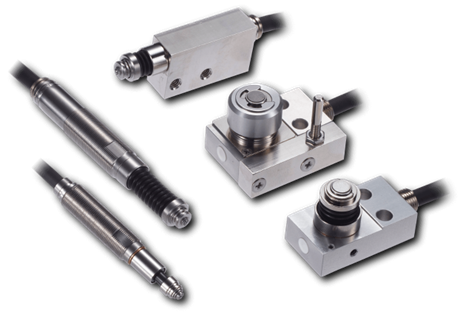
These are contact-type high-precision switches used for positioning and workpiece presence detection in machine tools, robots, and jigs. They achieve an extremely high repeatability of up to 0.5 µm and feature IP67-rated waterproof and dustproof protection, ensuring stable operation even in harsh environments. With more than 200 standard models available, they offer a wide range of variations, including designs for confined spaces, high-temperature environments, vacuum applications, and low contact force requirements.
Tool Setter (Tool Length Measurement Sensor)
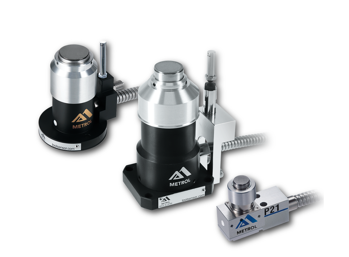
This is a contact-type sensor installed on CNC machine tools and industrial robots for tool length measurement, reference position setting, and tool breakage detection. By automatically measuring and compensating for tool length, wear, and thermal displacement inside the machine, it helps prevent machining defects and significantly reduces setup time. It is one of Metrol’s best-selling products, with a proven track record of more than 500,000 units shipped in 74 countries worldwide.
Touch Probe (On-Machine Measurement Probe)
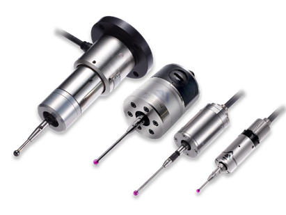
This is a contact-type probe for in-machine measurement, installed on machine tools and robots to automatically perform workpiece positioning (centering) before machining and dimensional measurement after machining. With a repeatability of 1 µm, it automates workpiece referencing and dimensional inspection, replacing skilled manual operations to reduce setup time and help prevent machining defects. Both wired and wireless models are available, meeting retrofit needs for 5-axis machining centers and robotic applications.
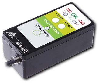
Air Gap Sensor (Pneumatic Sensor)
This is a non-contact sensor that uses air pressure to detect workpiece seating conditions with micron-level accuracy. It can detect gaps (“lift”) of less than 10 µm—previously difficult to measure—with a repeatability of ±0.5 µm, helping prevent machining defects and equipment downtime caused by insufficient contact between the workpiece and fixture. The sensor is used in applications such as semiconductor manufacturing processes, precision part clamping operations, and grinding wheel positioning on grinding machines, and it is a smart sensor that also supports the international standard IO-Link communication.