What Is Machine Setup in Machining? A Thorough Guide from the Basics to Proven Time-Saving Tips
Setup work performed before machining on a machine tool is a critical preparation step—covering tool and fixture preparation, machine parameter setup, and secure workpiece clamping. When done quickly and accurately, it improves safety and machining accuracy, leading directly to higher productivity and lower costs.
This article explains the basic flow of setup, key precautions, and practical points from real shop-floor experience.
Table of Contents
What Is Setup in Machining?
“Setup” refers to the preparation and adjustment work required before executing machining on a machine tool.
Specifically, it includes mounting the workpiece, adjusting machine settings, and preparing workholding devices and cutting tools—bringing the machine into the proper condition before machining begins.
The purpose of proper setup is to build a foundation for safe and accurate machining.
When the machine is correctly set up, subsequent machining processes run smoothly, improving productivity and quality.
In machining, setup time is a form of controllable downtime; reducing and optimizing it directly translates into cost reduction and higher productivity.
Typical Workflow of Setup Operations
Below is a concrete, practical explanation of common setup steps in machining. It can help improve repeatability and support standardization on the shop floor.
Step 1: Pre-check and Cleaning

Before operating the machine, remove chips and dirt, and check that lubrication oil and coolant levels are appropriate.
Remove residues from the previous job, check for abnormalities in each machine area, and if necessary, remove and put away tools used in the prior process.
This includes, for example, verifying remaining oil/coolant levels and checking for potential interference from workpieces or fixtures.
Confirm that no chips or tools from the previous process remain on the machine or table to establish a safe and accurate baseline for setup.
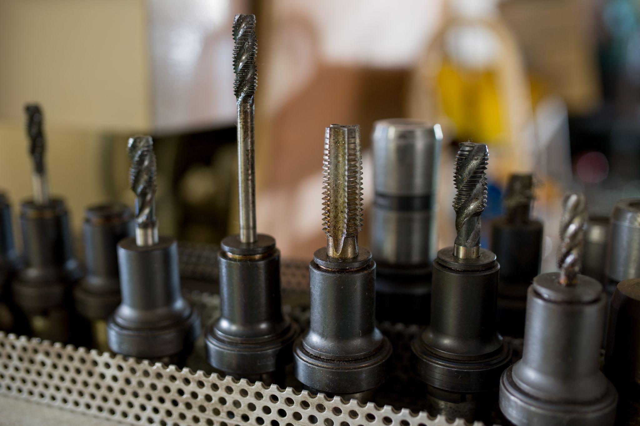
Step 2: Tool Preparation and Installation
Prepare the tools required for the next operation and install them on the machine.
Retrieve the required tools from the tool storage area and inspect them for wear or damage.
For NC machine tools, load the required tools into the magazine. If unnecessary tools from the previous job remain, remove them to secure empty slots.
It is also essential to confirm that tools are correctly mounted and properly tightened (with no looseness).
On CNC machines, setting and verifying tool length and diameter offset values are also performed at this stage.
Step 3: Fixture and Workpiece Mounting
Mount the material to be machined correctly on the machine tool.
On a milling machine, secure the material firmly to the table using a vise or clamps; on a lathe, grip it using a chuck or collet.
During mounting, it is important to align the workpiece orientation and position to match the drawing.
If clamping is insufficient, the workpiece may loosen or come off during machining, potentially damaging the machine or the part.
As needed, use locating fixtures, or on a lathe, provide additional support with the tailstock to ensure safe and stable mounting.
Step 4: Coordinate Alignment and Zero Setting
Set the reference position on the machine tool.
On CNC machines, you must set the origin (zero) to match the work coordinate system recognized by the program with the actual workpiece position.
Specifically, measure the workpiece reference surfaces using a touch sensor or edge finder, then set the work origin offsets in the X/Y/Z directions relative to the machine.
On a lathe as well, set tool offsets by aligning the tool tip to the workpiece end face and diameter.
Because coordinate setting directly affects machining accuracy, it must be done carefully.
In recent years, on-machine probing is also used to automatically measure and compensate workpiece position, helping reduce measurement errors from manual work.
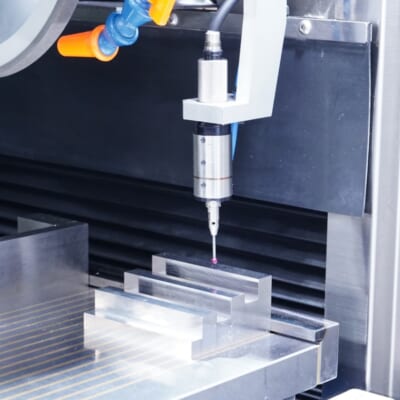
Automated workpiece centering and positioning
- Touch-probe -
a contact/touch sensor for on-machine measurement that improves the efficiency of setup work
Click here ›Step 5: Load and Verify the Program
For CNC machining, load the NC program (G-code) for machining into the machine.
Depending on the machine generation, methods vary—such as loading from a USB drive or transferring over a network.
In modern factories, machines may be connected via IoT networks, allowing programs to be downloaded directly from a central database.
After loading, confirm that the correct program version is selected and that the configured work coordinates and tool numbers are consistent.
In some cases, display and review the program before machining—especially checking the tool path for any hazardous motions.
Step 6: Trial Run / Dry Run
After setup, always perform a trial run.
On CNC machines, run the program line by line or perform an air-cut at a reduced feed rate to confirm tool motion and paths.
This step verifies whether the preset coordinates, offsets, and tool-change timing function correctly.
Some machines offer a “dry-run mode” that moves the tool without cutting, allowing you to check for collisions.
In some cases, operators also move the machine manually to check for interference.
During trial runs, the operator should monitor machine movement carefully and stay ready to stop immediately if any abnormal behavior occurs.
Step 7: First-Piece Inspection and Fine Adjustment
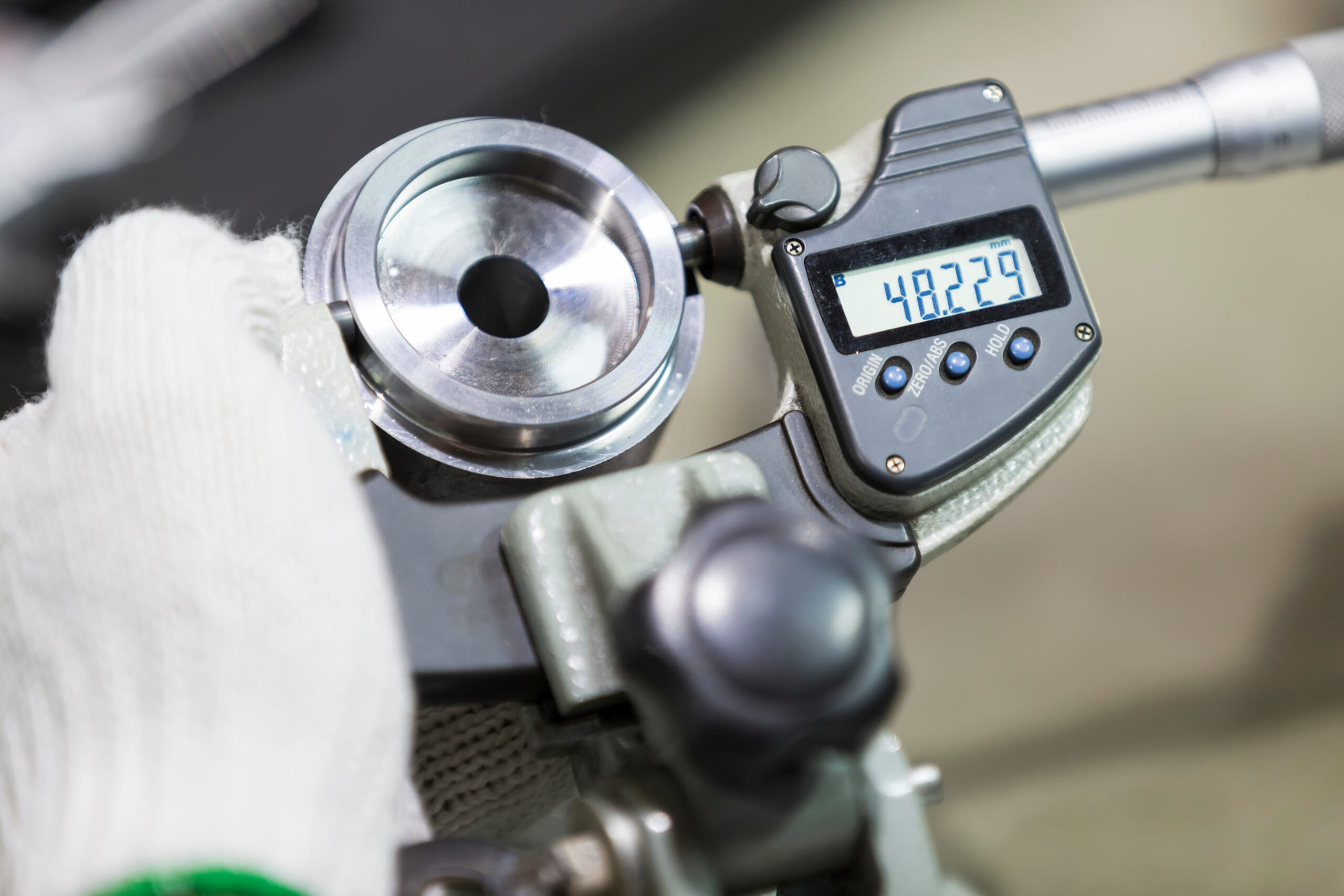
After the trial run or after machining the first part, inspect the result.
Using measuring instruments and inspection tools, measure critical dimensions and geometry to confirm they fall within the drawing tolerances.
If dimensions are out of spec, adjust tool offsets and/or revise the program.
This first-piece check verifies whether setup was performed correctly (e.g., no workpiece misalignment or tool-data errors).
If there are no issues, proceed to full-scale production. If problems are found, correct them at this stage to prevent mass defects.
That is the typical setup workflow. Setup is not just preparation—it is a critical process that determines machining quality and production efficiency.
Setup Methods and Precautions by Major Machine Tools: Differences Among Lathes, Milling Machines, and Machining Centers
Even though all of it is called “setup,” the specific work content and precautions differ depending on the type of machine tool.
Here, we explain the setup characteristics and key precautions for major machines: lathes, milling machines, and machining centers.
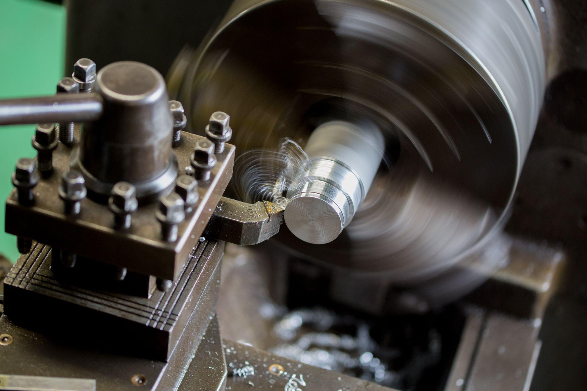
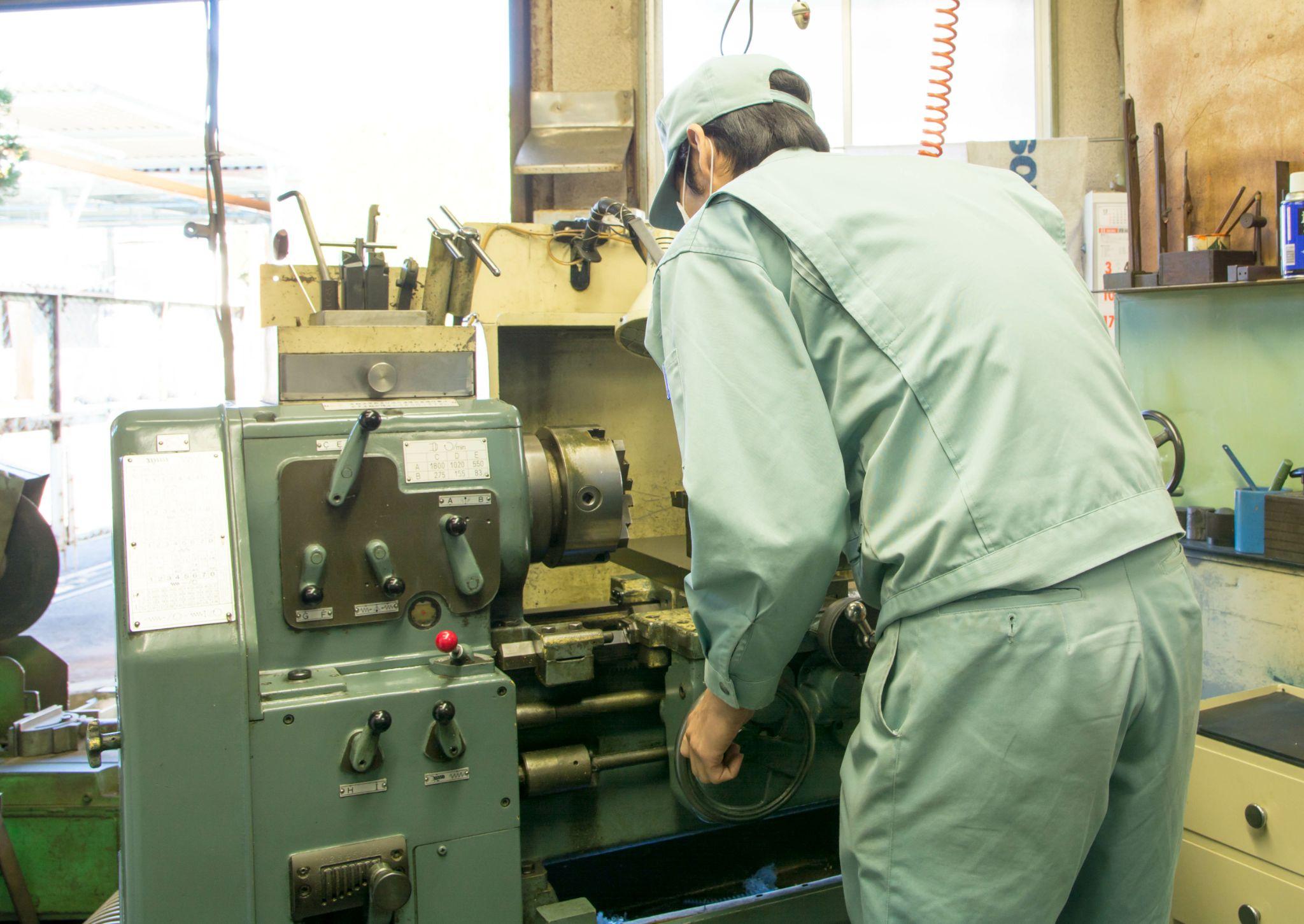
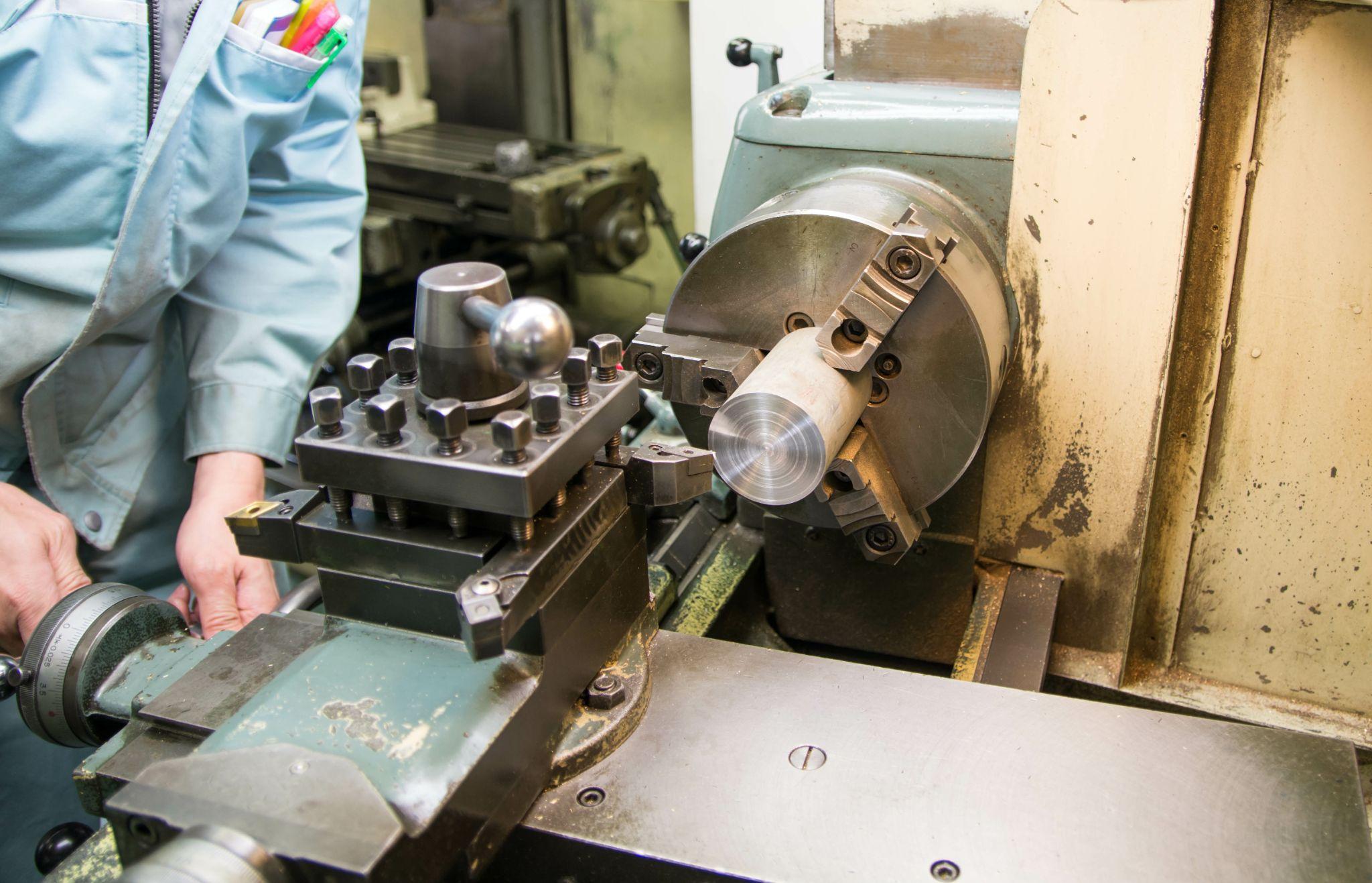
How to Set Up a Lathe: Characteristics and Key Precautions
Lathe setup refers to the series of preparation tasks required to securely clamp the rotating workpiece and correctly set tool positions and machining conditions.
Because safety is critical on a lathe, you must firmly master the basics—such as handling the chuck and tailstock and centering the tool tip properly.
This section explains lathe setup procedures and the key points you should watch for.
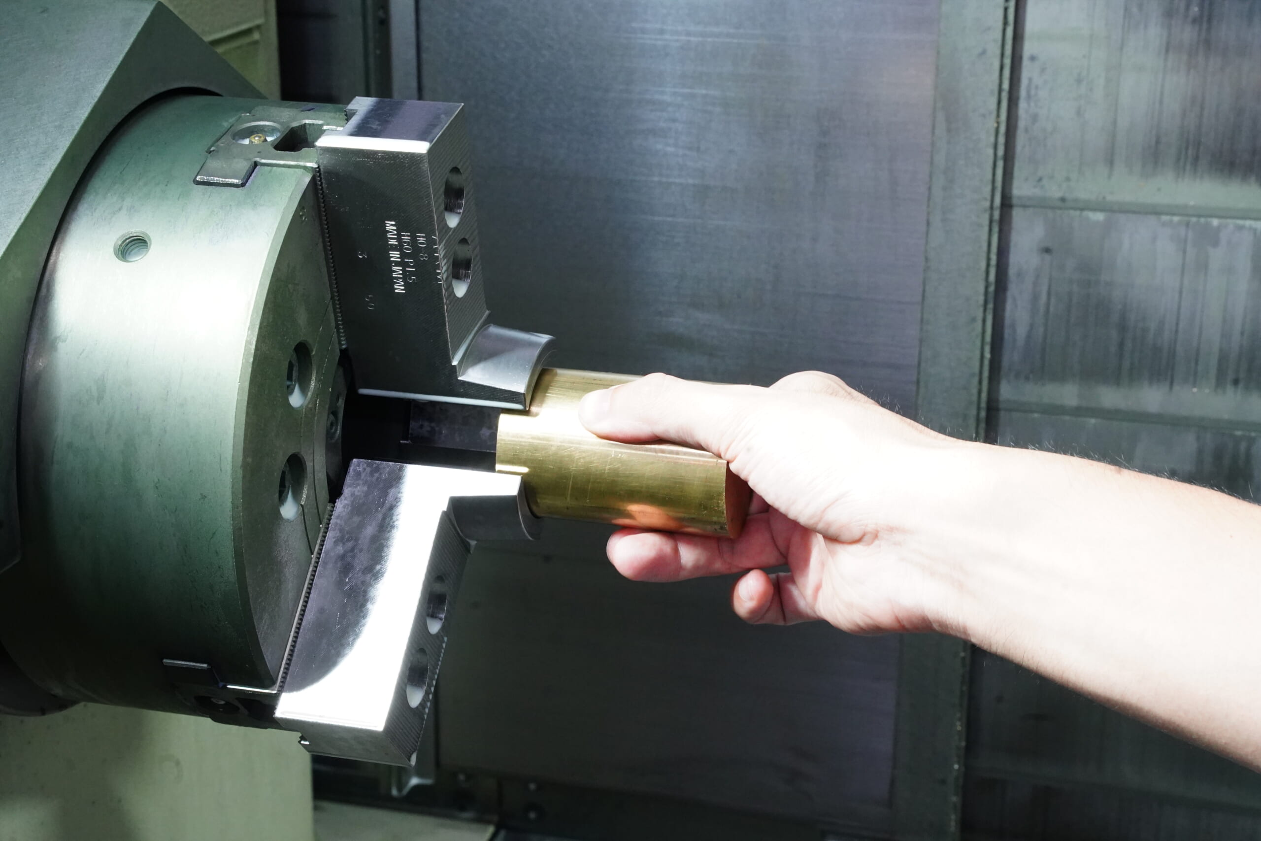
How to Clamp a Workpiece on a Lathe: Selecting the Chuck and Using the Tailstock
On a lathe, material (such as round bar stock) is gripped using a chuck or collet.
During setup, pay close attention to selecting and mounting chuck jaws, and clamp the workpiece securely.
Poor chuck maintenance or insufficient clamping can cause the workpiece to be thrown out during machining.
For safety, remove the chuck key immediately after use, and always confirm it has not been left in place before starting the machine.
When possible, use the tailstock to stabilize the workpiece.
For long or unstable workpieces, support them in a “between supports” configuration using both the chuck and tailstock to maximize stability and machining accuracy.
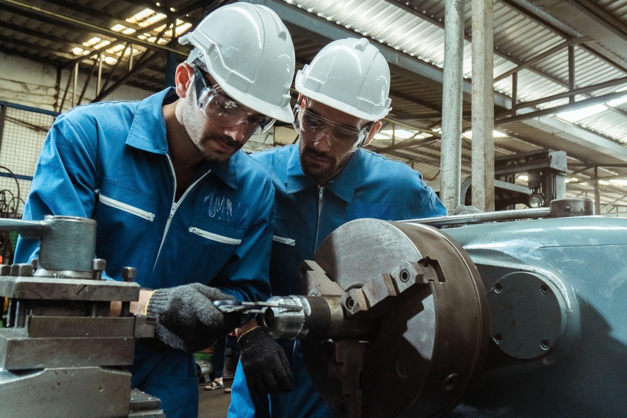
Why Safety Checks Matter in Lathe Work: Setup Rules to Prevent Accidents
A lathe is inherently hazardous because the workpiece rotates at high speed and the chuck and spindle are exposed—more so than machines protected by perimeter guards.
Therefore, operators must pay even more attention to clothing and behavior than with other machine tools.
During both setup and machining, tighten cuffs and tie back hair to prevent gloves, ties, loose sleeves, or hair from being caught.
Strictly follow basic rules: never touch chips by hand during machining, and do not bring your hands close for measurement or cleaning until the lathe has completely stopped.
In addition, always use safety devices such as chuck covers and splash guards when available.
Because lathes are especially prone to accidents caused by “familiarity” or “complacency,” it is essential to stay alert even during setup.
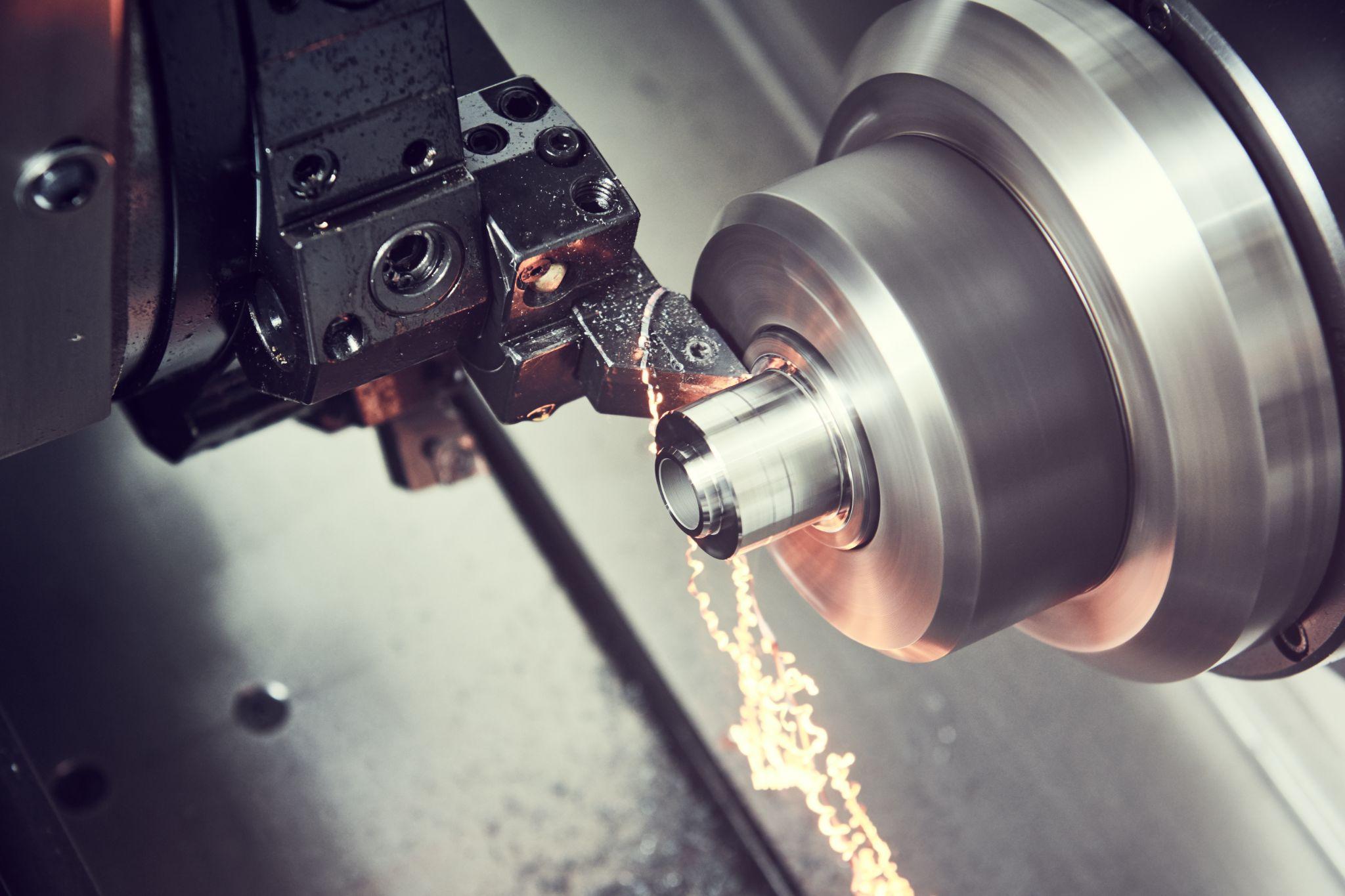
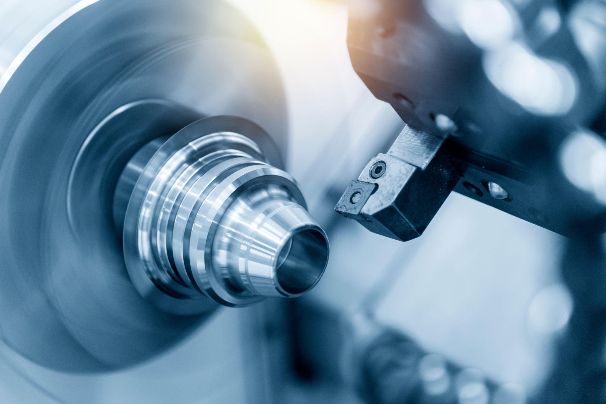
Originating the blade of CNC Lathe
- Tool Setter -
performs wear, chipping, and thermal displacement compensation, contributing to maintaining the constant machining precision of the machine tool
Click here ›How to Set Up a Milling Machine: Procedure and Important Points
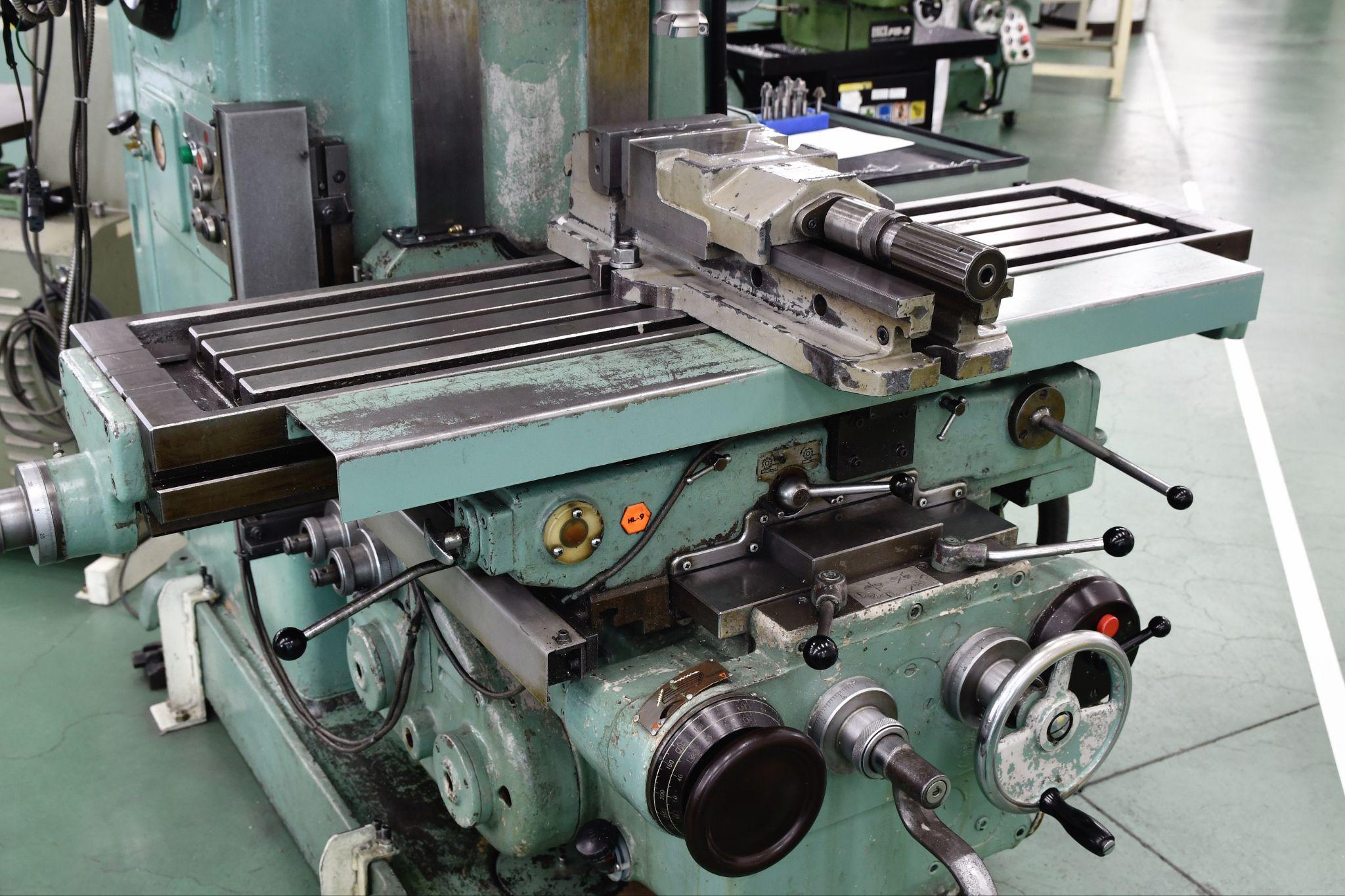
Milling machine setup involves accurately clamping the workpiece to the table and establishing its position and reference points to prepare for cutting.
There are many key elements that form the foundation of accurate machining—especially proper vise use and reference measurement with an edge finder.
This section explains milling machine setup procedures and the points you should pay attention to.
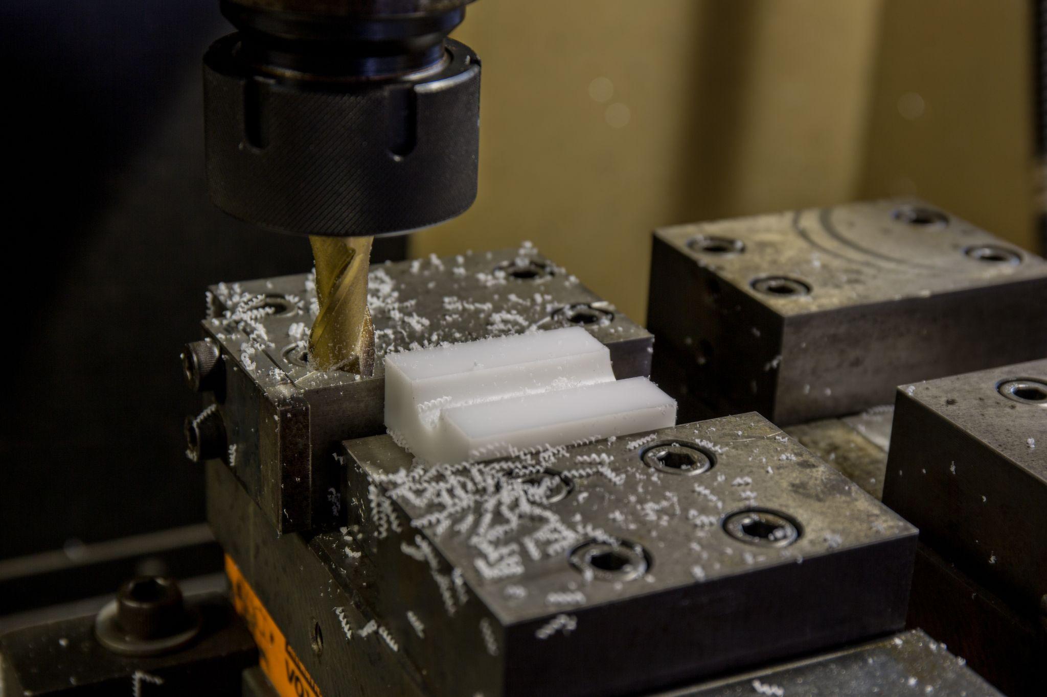
Workholding on a Milling Machine: How to Use a Vise and Clamps
On a milling machine, the workpiece is clamped onto a flat table.
Typically, you either use a vise or clamp directly to the T-slots with bolts and clamps.
First, confirm that the workpiece and fixture are seated with good parallelism and flatness on the table.
When clamping in a vise, lightly tap the material with a hammer to seat it and ensure full contact.
Confirm that clamps and bolts are tightened with no looseness, will not come off during cutting, and are positioned so they do not obstruct the tool path.
After setup, manually rotating the spindle or end mill to check clearance against fixtures and bolts on the table is also an effective safety measure to prevent accidents.
Key Points for Zero Setting and Reference Alignment in Milling
On a milling machine, you must establish the workpiece reference position and parallelism.
For example, when clamping a rectangular block in a vise, measure a side face with a dial indicator or edge finder and adjust to ensure it is mounted parallel to the vise.
As needed, use setup blocks or parallels so the machined surface is set parallel.
To define the work origin for each XYZ axis, pick up the X/Y zero positions (end faces) using an edge finder, and for Z, lightly touch the tool to the workpiece or stop with a paper-thickness gap to establish the Z zero height.
Accurate reference setting is the basis of setup, and its precision directly determines machining accuracy.
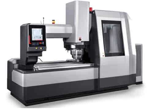
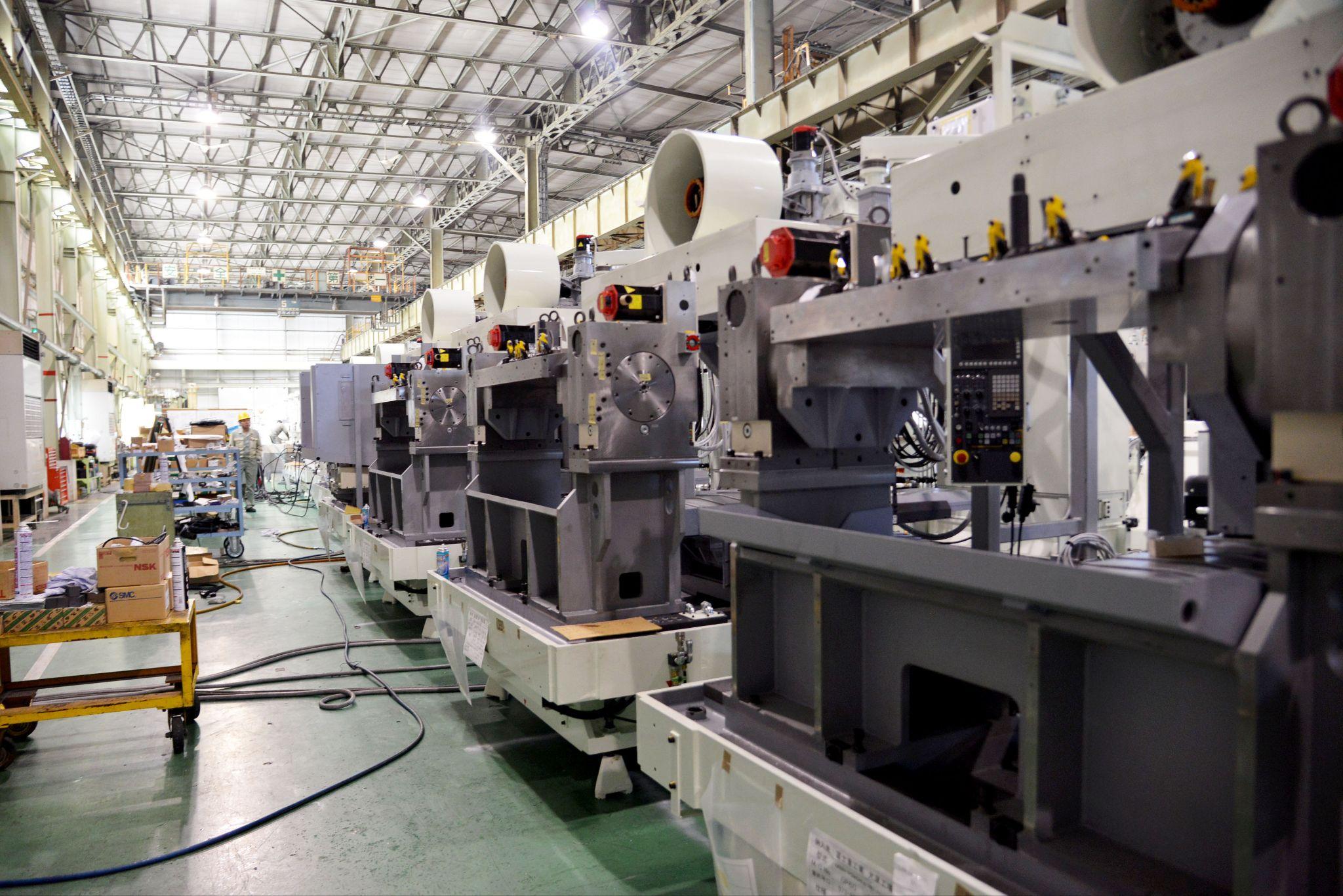
How to Set Up a Machining Center: Procedure and Important Points
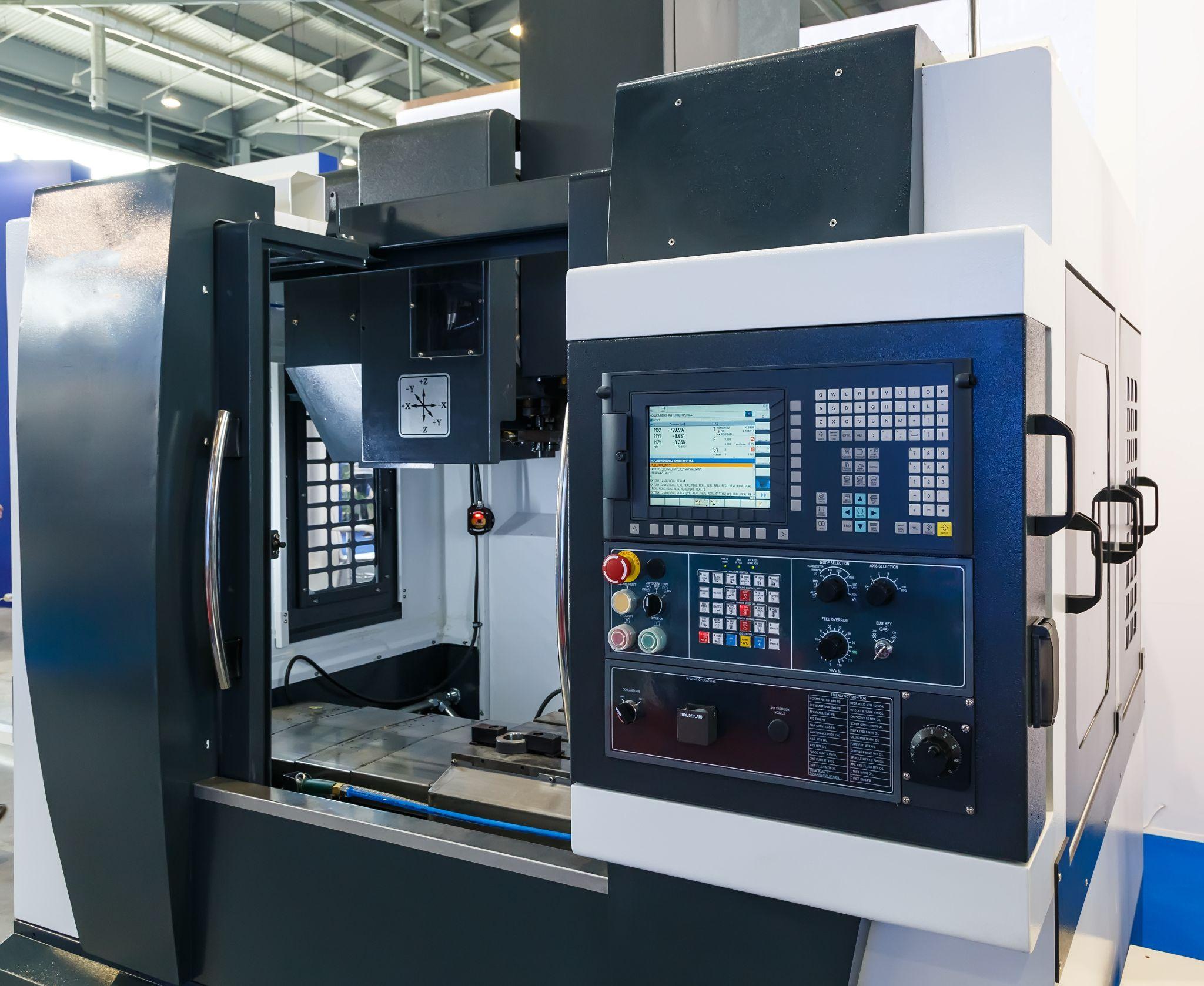
Machining center setup is an advanced preparation task: installing many tools in the magazine and ensuring complete consistency among the machining program, tool settings, and workpiece position.
The more automated the equipment, the more pre-checks and offset management determine machining quality and safety.
This section explains how to set up a machining center.
Streamlining Procedures Using Automatic Tool Change on a Machining Center
A machining center is an NC machine tool equipped with automatic tool change, enabling continuous machining with many tools.
During setup, load all tools required by the machining program into the magazine and set them in the correct tool numbers and order.
When there are many tools, it helps to organize them on a dedicated cart while referencing a setup sheet, and to measure/register lengths in advance using a tool presetter for smoother setup.
On machines with limited magazine capacity, you must unload tools from the previous job to create space—so the setup plan should include tool swap procedures.
Checking Consistency Between the NC Program and Tool Settings: Setup Verification Points
Machining centers are highly automated, which makes consistency between the NC program and the actual machine settings especially important.
During setup, verify there are no discrepancies between tool/offset numbers called in the program and the tools actually installed and their registered measurement values.
For example, if Tool #5 is physically a drill but the program assumes Tool #5 is an end mill, that mismatch can cause a serious collision.
Therefore, after setup, always perform an “air-run simulation,” or at minimum read the program header and cross-check the tool list and offset table.
Many CNC controllers include a “graphic simulation” feature that traces the tool path on-screen so you can check the machined shape and potential interference—use it whenever possible.
Automates originating of cutting tools
- Tool Setter -
Tool length and chips is monitored to prevent machining defects due to wear and thermal displacement
Click here ›What Is SMED? Implementation Steps and How to Reduce Setup Time
SMED (Single-Minute Exchange of Dies) is a systematic approach—well known through the Toyota Production System—aimed at dramatically reducing changeover (setup) time in manufacturing equipment.
The core idea of SMED is to identify every element involved in setup and classify tasks into internal setup (must be done while the machine is stopped) and external setup (can be done in parallel while the machine is running).
It shifts as much work as possible to external setup, then simplifies and parallelizes the remaining internal tasks to minimize downtime for changeover.
Reducing setup time is a key theme for improving productivity.
This section explains SMED implementation steps and practical methods for reducing setup time.
Five Steps to Implement SMED and Practical Tips
Step 1: Understand the Current Setup Process
Observe every task included in the current setup and measure the time required. Identify where waste exists. Visualizing procedures through video recording can also be effective.
Step 2: Separate Internal and External Setup
Classify the identified tasks into internal and external setup. Tasks feasible during operation are external setup; tasks requiring machine stoppage are internal setup.
Step 3: Convert Internal Setup into External Setup
Look for internal tasks that can be converted to external through ingenuity. For example, introducing setup fixtures to simplify positioning can allow tasks previously done during downtime to be performed outside the machine.
Step 4: Simplify and Standardize Work
For tasks that remain internal, devise ways to reduce time—review whether steps can be eliminated and create simple, highly repeatable procedures. Standardize setup procedures and convert them into checklists to enable quick, accurate execution.
Step 5: Continuous Improvement and Training
SMED is not a one-time effort—continuous improvement is essential. Practice on the shop floor, gather feedback, and look for further opportunities to eliminate waste. Training and education of employees are also indispensable.
Useful Tools and Practical Ideas to Reduce Setup Time
What Is a Tool Presetter for Converting Tool Setup to External Setup?
Using a tool presetter that allows tool length and diameter offsets to be measured and registered in advance enables tool setup to be completed outside the machine—significantly reducing tool-setting time during setup.
If tool length compensation is completed offline and setup only requires “mounting the tool on the machine,” preparation can proceed without stopping the machine.
A tool presetter enables off-machine tool setup, and it also helps detect tool wear in advance and reduce human error.
Improve Setup Efficiency with One-Touch Change Fixtures and Tools
Another effective approach is to introduce setup-specific mechanisms into the equipment itself.
For example, using zero-point clamps or quick-change chucks that attach/detach with a single action can drastically reduce time spent on bolting work during fixture changes.
For tooling as well, quick-change tooling systems can reduce setup effort.
In short, reducing setup time requires both “methodology (SMED principles)” and “concrete actions (tools/equipment adoption and workflow improvements).”
Setup Time-Reduction Tips from Shop-Floor Experience
The best and easiest ways to reduce setup time vary depending on each shop’s equipment and environment.
Here are a few examples.
Reduce Setup Time Using Locating Pins
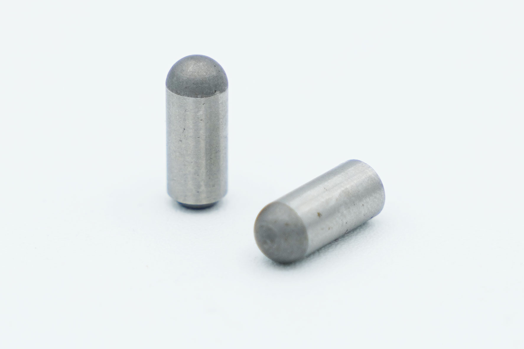
Using locating pins when mounting fixtures can reduce the time required to measure the origin during setup.
If locating-pin holes are machined into the machine table in advance, you can set the fixture against the pins and machine from the same origin every time.
If fixtures to be mounted on the machine are designed and built to match pre-machined locating-pin holes, similar setup can be achieved even when machining on another machine.
This is especially effective when machining complex castings, where “measuring the machining origin” and “tramming/aligning parallelism” take time—use locating-pin-based setup to achieve major time reductions.
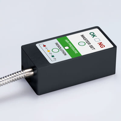
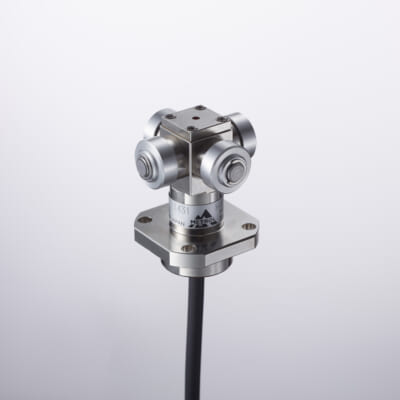
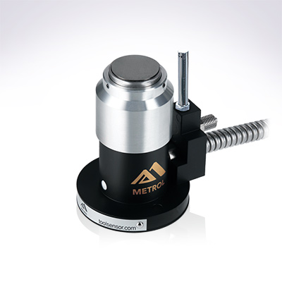
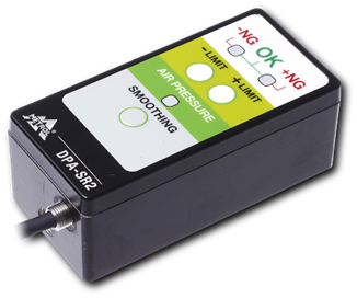
High-precision seating confirmation of workpiece and jig
- Air Gap Sensor -
you can check not only "presence/absence" but also "adhesion (gap)" at the same time with a repeatability of ±0.5μm.
Click here ›Shorten Setup Time by Using Common Dedicated Tools
If your machines have common dedicated tools that can be shared in their magazines, leveraging those tools is an effective way to reduce setup time.
Especially for horizontal machining centers or simultaneous 5-axis machines, it is not uncommon to have large equipment with magazine capacities exceeding 100 tools.
If dedicated tools used for mass-production line machining can also be used for new or single-piece setups, use them to reduce the effort required for external setup.
Preparing new tools increases effort and time—such as pre-use regrinding and verifying correct tool placement.
Therefore, for machines with many magazine slots, simply creating a “tool list” for each machine and keeping it near the control panel can reduce setup time.
Because dedicated tool configurations and tool management numbers vary by the products machined on each machine, store machining program data used with dedicated-tool-based setup as machine-specific data.
How to Manage Tool Lengths for More Efficient Setup
Simply storing tool lengths can help reduce setup time.
Without tool length management, you must re-enter tool lengths at every changeover—costing more time and effort as the number of tools increases.
It is recommended to include comments/notes about tool length offset numbers in work instructions and machining programs to make setup handovers smoother.
What Is a Pallet Change System? How It Reduces Setup Time
A pallet change system is a device that unloads a pallet carrying a completed workpiece and automatically loads the next pallet into the machine.
If you unload another pallet outside the machine while it is running and mount fixtures or swap to the next part in a separate work area, you can change over without stopping the operating machine—even if the changeover itself takes time—eliminating time loss.
As a precaution, when reloading an external pallet into the machine, do not mistake the pallet orientation, and be sure to remove any tools or foreign objects left from external work.
What Are Metrol’s High-Precision Positioning Sensors?
In machining, improving production efficiency by streamlining setup operations is a critical challenge.
Sensors play an essential role in detecting distance to a target and positioning workpieces efficiently.
Whether you can align the tool tip and workpiece exactly as intended—down to the micron level—significantly affects quality, yield, and production efficiency.
Here, we introduce Metrol’s sensor products, from a specialist manufacturer supporting high-precision positioning.
High-Precision Positioning Touch Switches
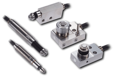
These are contact-type high-precision switches used for positioning and workpiece presence detection in machine tools, robots, and jigs. They achieve an extremely high repeatability of up to 0.5 µm and feature IP67-rated waterproof and dustproof protection, ensuring stable operation even in harsh environments. With more than 200 standard models available, they offer a wide range of variations, including designs for confined spaces, high-temperature environments, vacuum applications, and low contact force requirements.
Tool Setter (Tool Length Measurement Sensor)
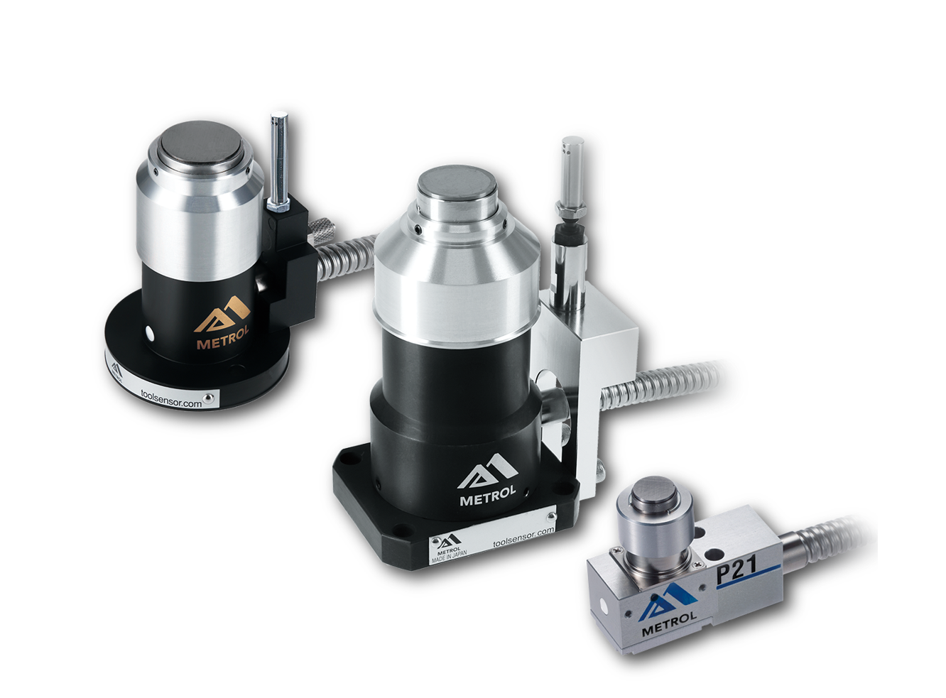
This is a contact-type sensor installed on CNC machine tools and industrial robots for tool length measurement, reference position setting, and tool breakage detection. By automatically measuring and compensating for tool length, wear, and thermal displacement inside the machine, it helps prevent machining defects and significantly reduces setup time. It is one of Metrol’s best-selling products, with a proven track record of more than 500,000 units shipped in 74 countries worldwide.
Touch Probe (On-Machine Measurement Probe)
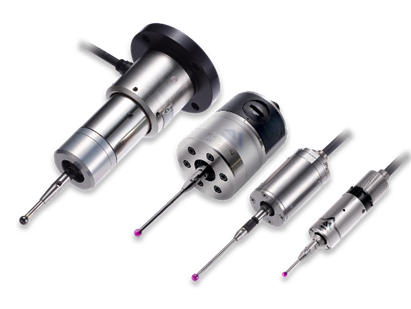
This is a contact-type probe for in-machine measurement, installed on machine tools and robots to automatically perform workpiece positioning (centering) before machining and dimensional measurement after machining. With a repeatability of 1 µm, it automates workpiece referencing and dimensional inspection, replacing skilled manual operations to reduce setup time and help prevent machining defects. Both wired and wireless models are available, meeting retrofit needs for 5-axis machining centers and robotic applications.
Air Gap Sensor (Pneumatic Sensor)
This is a non-contact sensor that uses air pressure to detect workpiece seating conditions with micron-level accuracy. It can detect gaps (“lift”) of less than 10 µm—previously difficult to measure—with a repeatability of ±0.5 µm, helping prevent machining defects and equipment downtime caused by insufficient contact between the workpiece and fixture. The sensor is used in applications such as semiconductor manufacturing processes, precision part clamping operations, and grinding wheel positioning on grinding machines, and it is a smart sensor that also supports the international standard IO-Link communication.