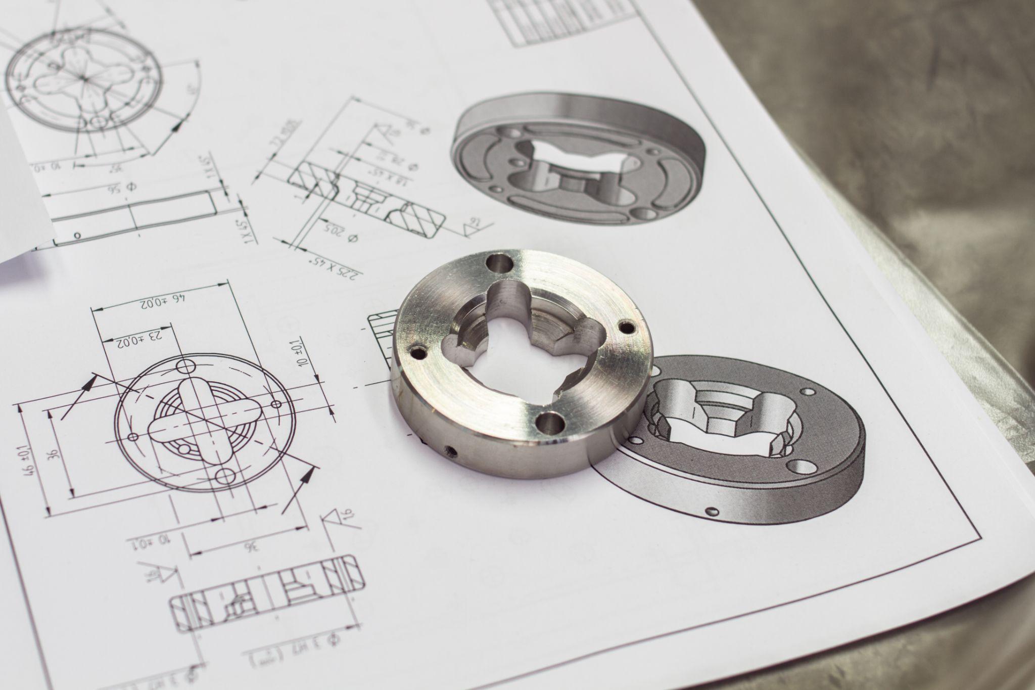
What Is Machining? A Clear Guide to Methods, Automation, and Design Improvements
Machining is a manufacturing method that achieves the shapes and dimensions required for a product by removing material through processes such as cutting and slicing.
On manufacturing floors, a wide range of machining methods are used with equipment such as lathes and milling machines, and there is constant demand for higher accuracy and productivity.
This article explains, in an easy-to-follow way, how major machining methods work, the benefits of growing automation in recent years, and practical design considerations that improve manufacturability.
It’s useful not only for those involved in machining operations and design, but also for beginners.
Table of Contents
What Is Machining? A Simple Explanation of the Basics and Key Methods
Machining is a manufacturing process that removes unnecessary material from a workpiece to obtain the intended shape and dimensions.
Although it was developed primarily for metalworking, it can also be applied to a wide range of materials such as wood, plastics, ceramics, and composites.
Typical machining methods include turning and milling with cutting tools, drilling to create holes, and grinding using abrasive wheels—each of which removes material with machine tools and cutting edges.
Machining is a core process in metal product manufacturing and is essential for producing parts that require high dimensional accuracy and surface finish—from automotive engine components to precision aircraft parts.
There are many types of machining depending on the purpose and tooling. Below are major methods and their characteristics.
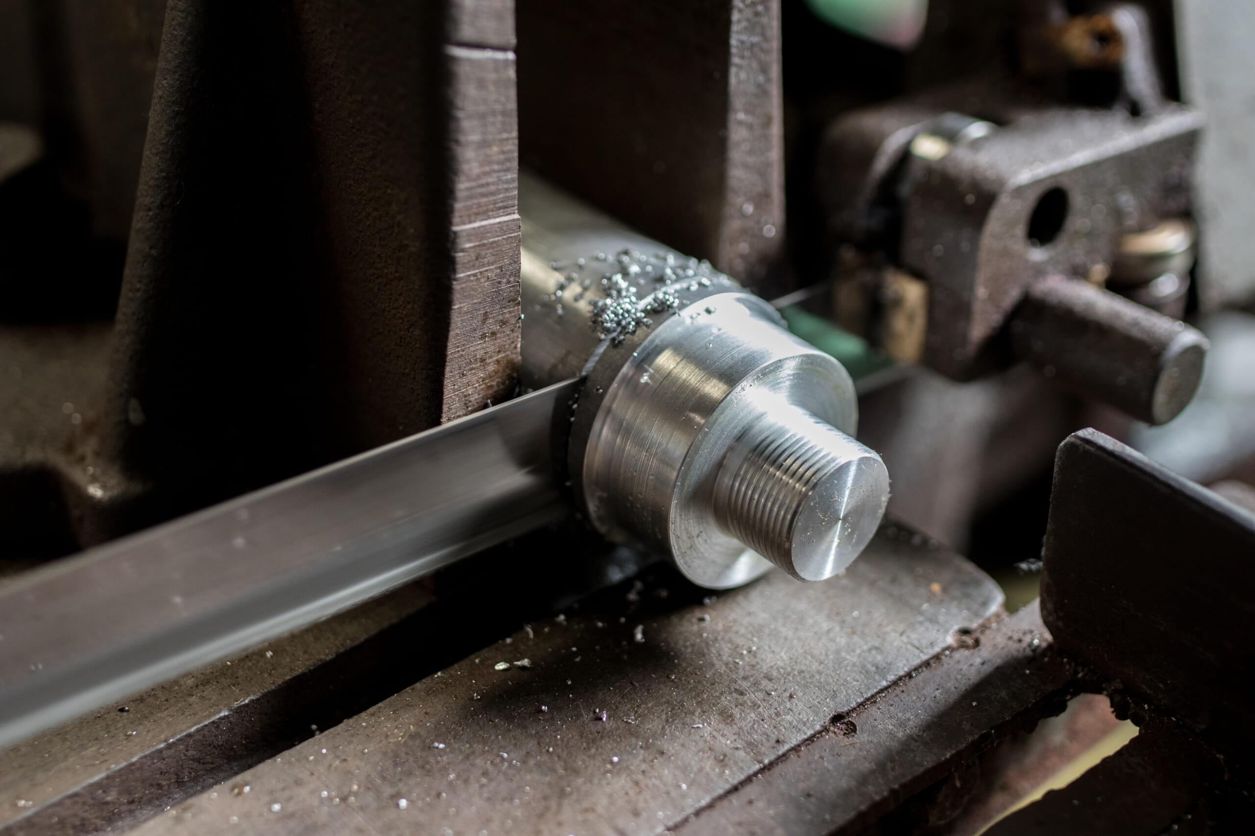
What Is Turning? How It Works and Key Characteristics
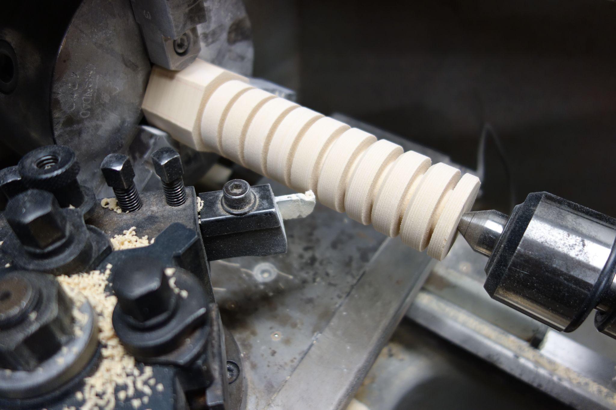
Turning is a process in which a cylindrical workpiece is rotated at high speed while a single-point tool called a turning tool (bit) is applied to remove material.
This allows you to machine shafts or disks from bar stock, and to cut threads or grooves on the product surface.
Because the workpiece rotates, turning is well suited to precision “rotationally symmetric” parts and can achieve excellent cylindricity and straightness.
Common examples include automotive shafts, bearing races, and fasteners such as screws and bolts, which are often finished to high accuracy through turning.
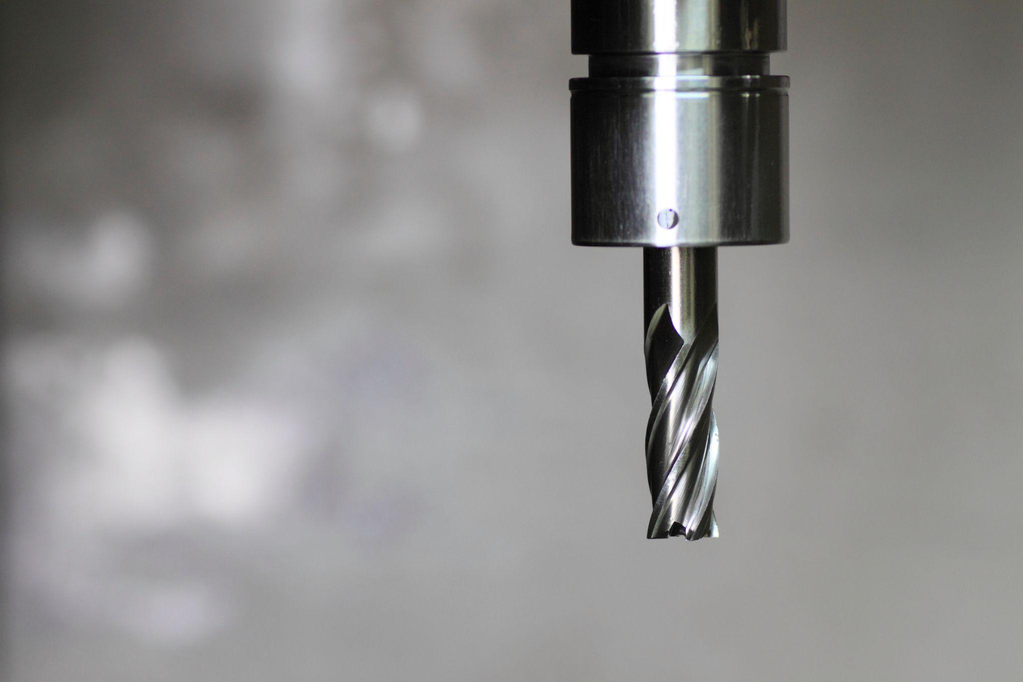
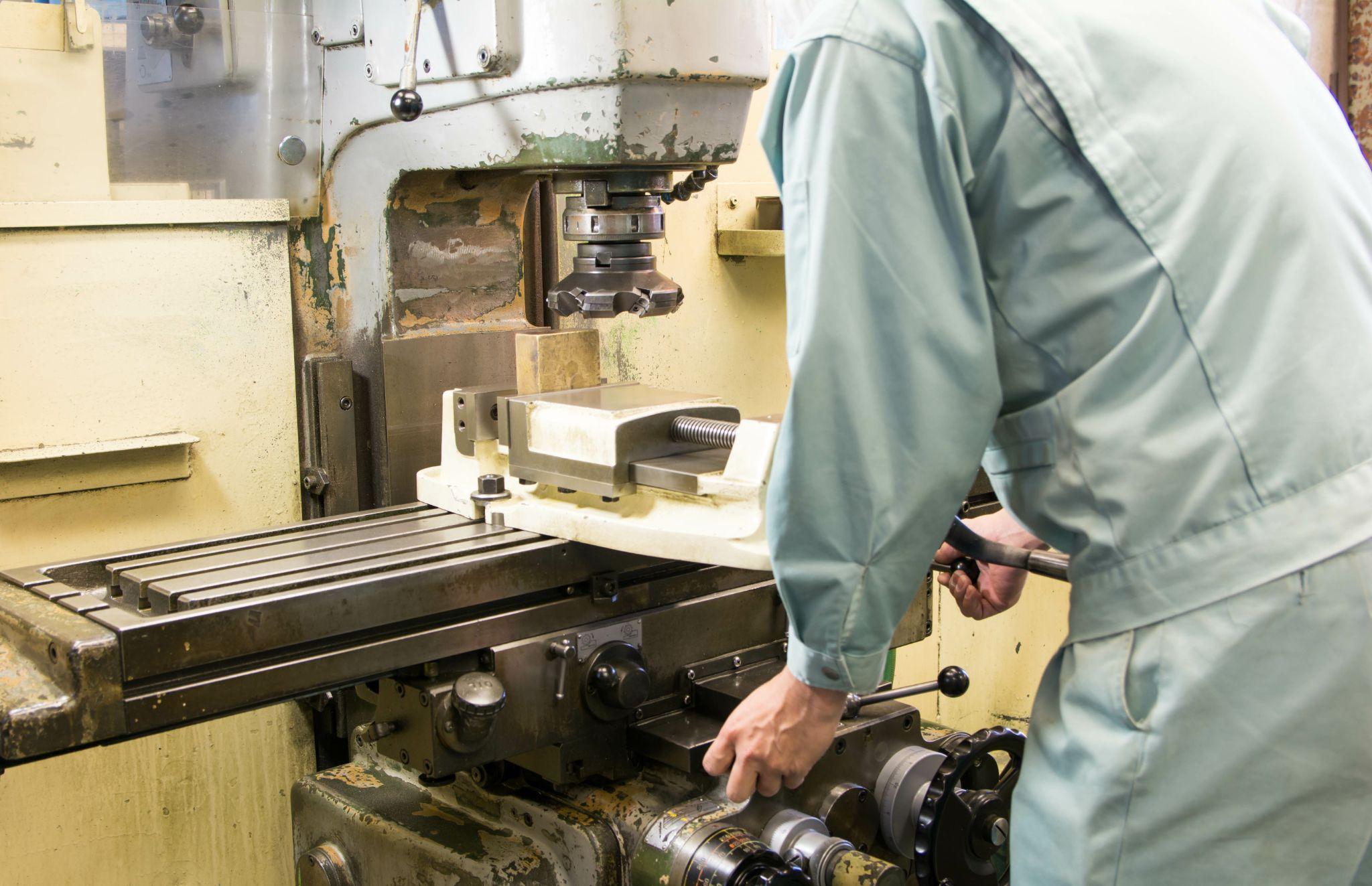
What Is Milling? A Machining Method Using Rotary Cutting Tools
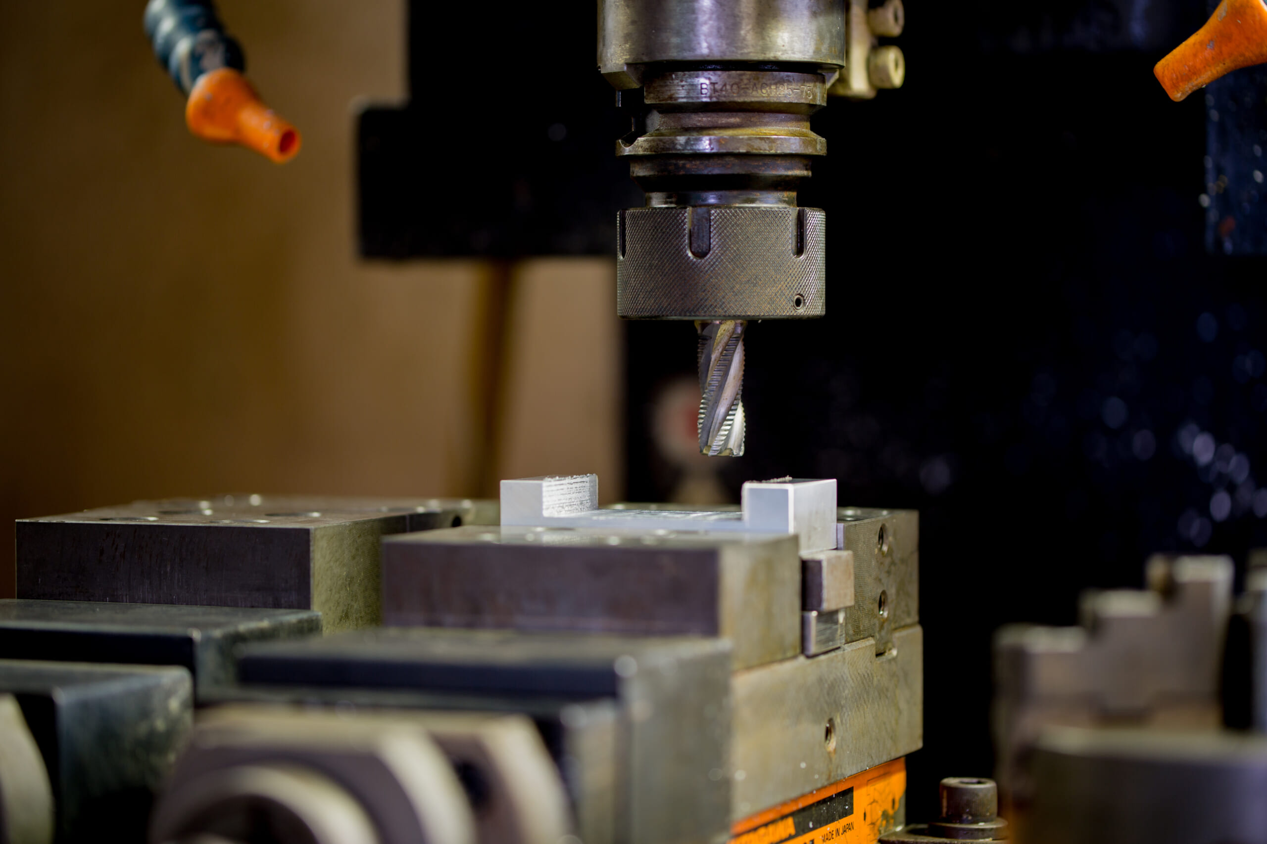
Milling is a machining method that uses a milling machine (machining center) to cut a workpiece by moving a multi-edge rotary tool along various axes.
Milling cutters have multiple cutting edges on the tip and/or sides and remove material while rotating at high speed.
It is highly versatile, covering face milling (planar surfaces), slots and steps, gear cutting, and contour machining of complex curved surfaces.
Vertical and horizontal milling machines, as well as 3- to 5-axis machining centers, are used across a wide range of applications—from 3D surface machining of aircraft parts to mold and die manufacturing.
Automates originating of cutting tools
- Tool Setter -
Tool length and chips is monitored to prevent machining defects due to wear and thermal displacement
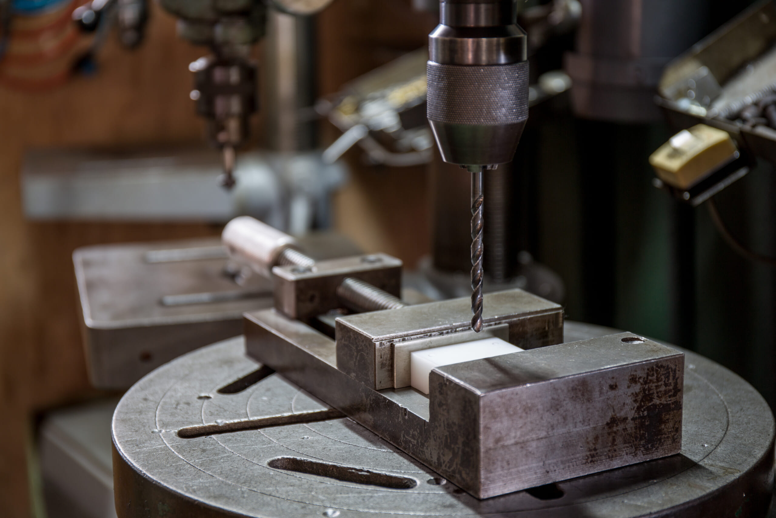
Click here ›What Is Drilling? Making Holes in a Workpiece with a Drill
Drilling is a process that creates holes by rotating a spiral tool called a drill at high speed and feeding it into the workpiece.
It may include steps such as pilot drilling, boring, and reaming (final sizing/finishing), enabling cylindrical holes—such as bolt holes and bearing bores—to be produced with high roundness.
Drilling is performed on dedicated drill presses or machining centers, using drill bits of different diameters as needed to achieve the target hole size and depth.
For deep holes, specialized tools such as gun drills and “oil-hole drills” (which can supply cutting fluid at high pressure through the tool) are used, and tool geometry and cutting conditions are optimized to match the material and purpose.
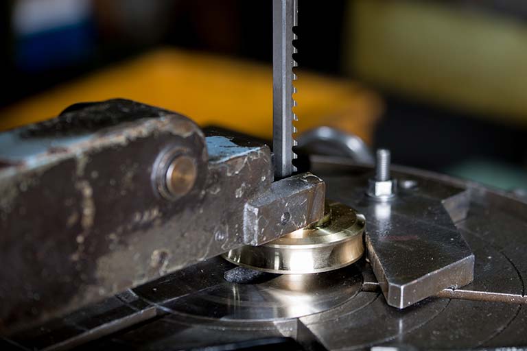
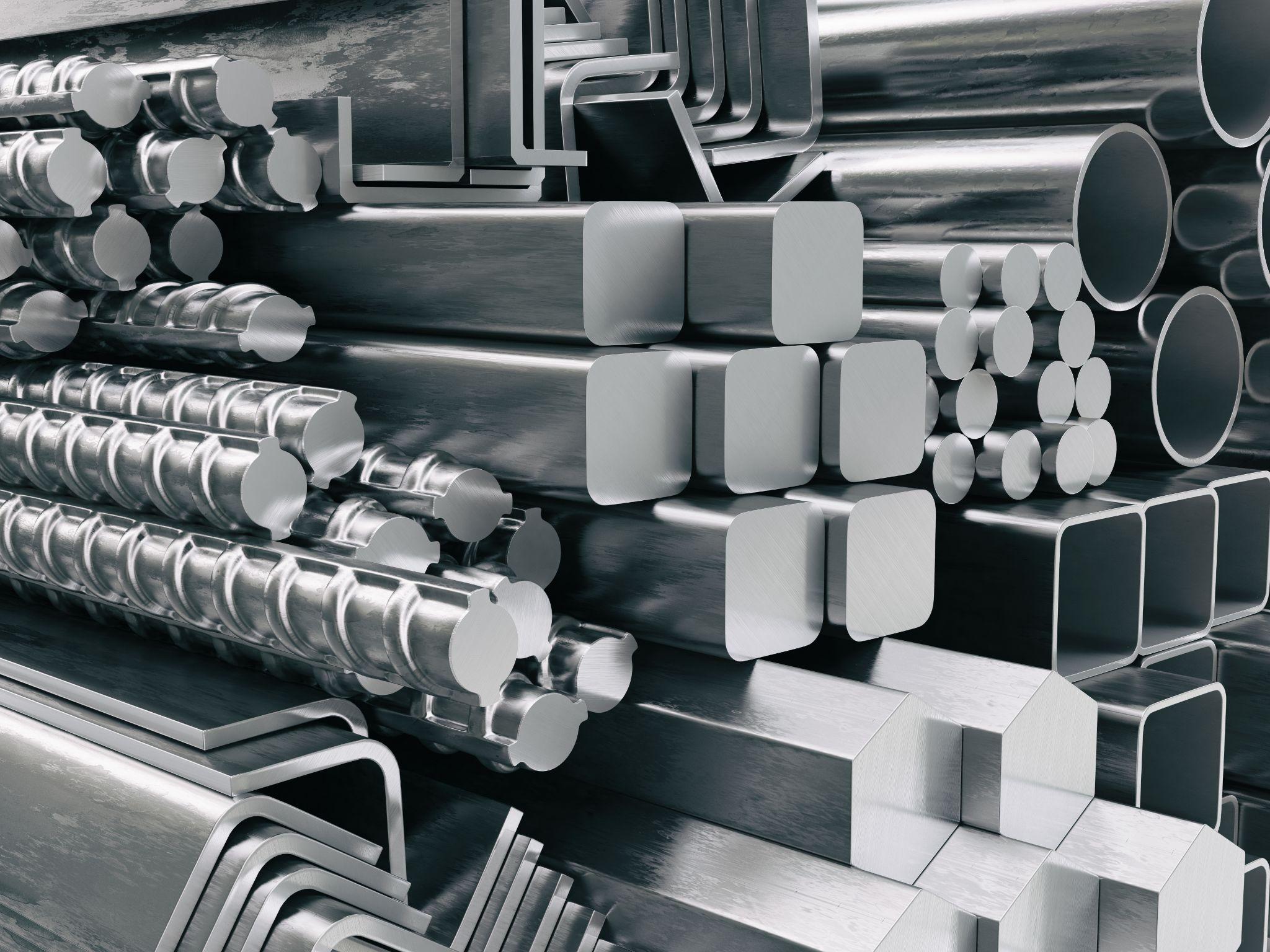
What Is Saw Cutting? Cutting Processes Using a Blade
Saw cutting is a process that cuts material to size using toothed blades such as band saws or circular saws.
It is widely used as a roughing/preparation step, such as cutting bars to length or splitting plate stock into specified dimensions.
While the cut surface accuracy and roughness are not as high as other machining processes, it can cut large cross-section materials quickly, making it effective for pre-processing and stock preparation.
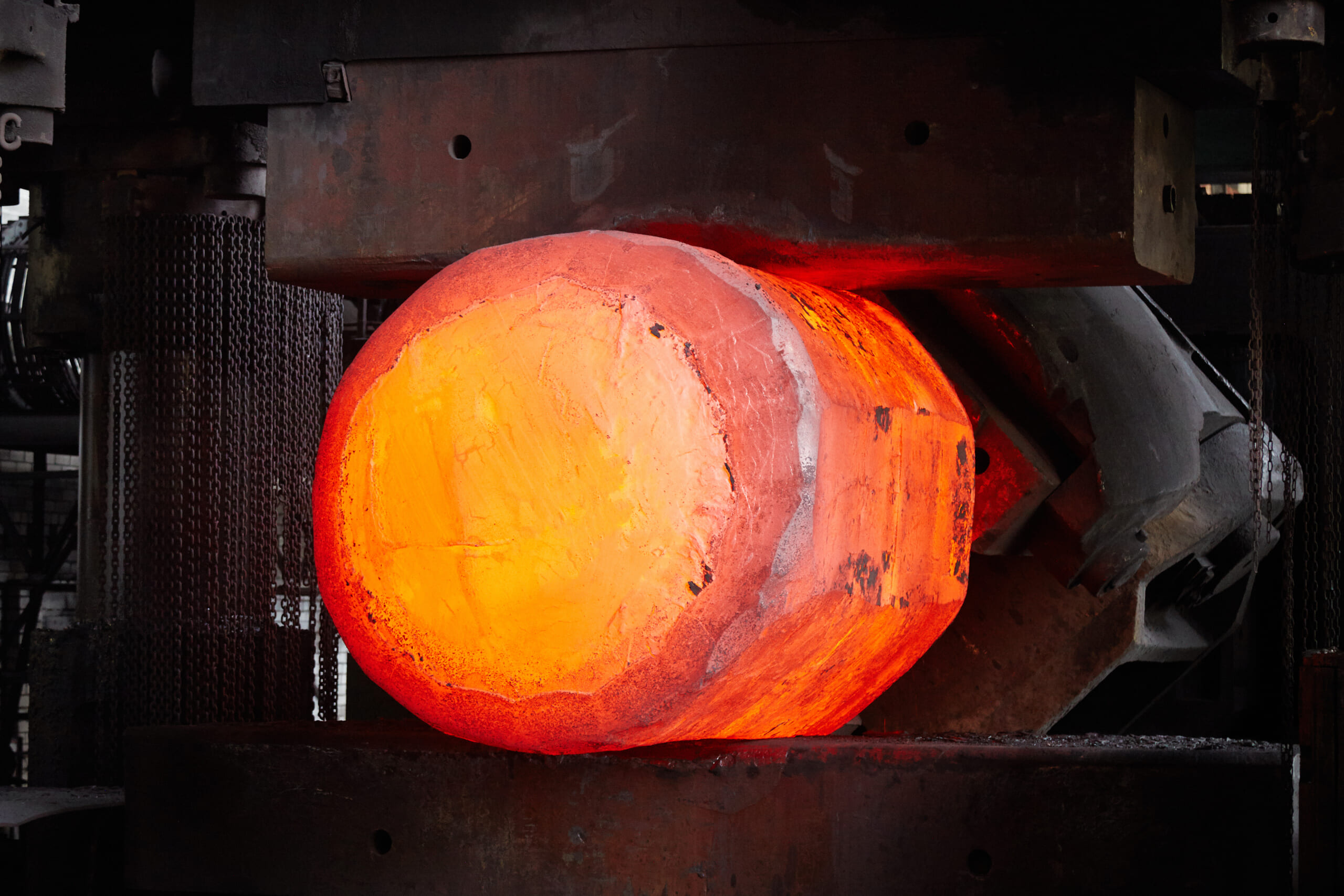
Machines such as band saws and pipe cutting machines are used, and the method is also employed when steel manufacturers cut materials to standard lengths for shipment.
What Is Grinding? Finely Removing Surface Material at High Speed
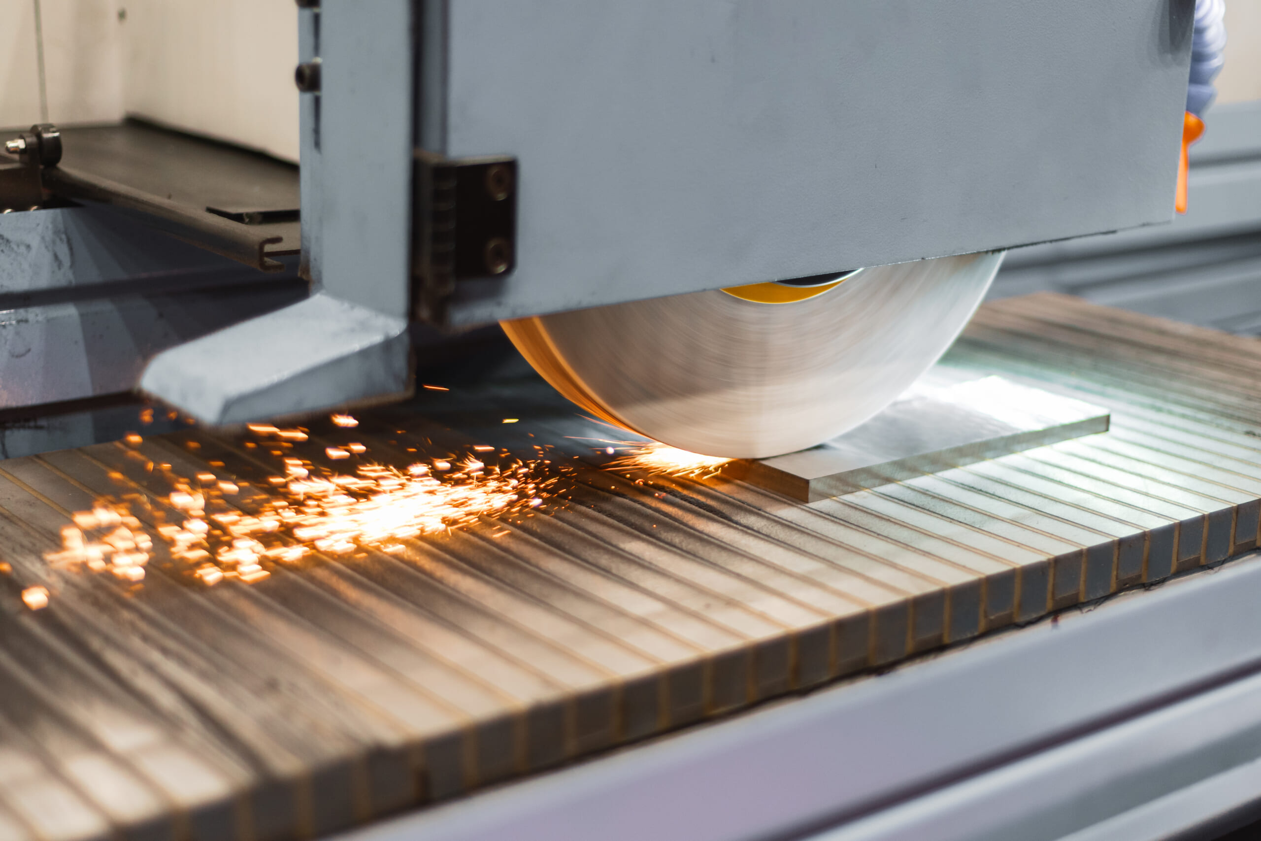
Grinding is a process that removes a very small amount of material from the workpiece surface by rotating a wheel made of fine abrasive grains (a grinding wheel) at high speed.
Performed on grinding machines, it is often used as a finishing step after cutting and can achieve very smooth surfaces (surface roughness Ra ≤ 1 μm) and high dimensional accuracy.
Examples include finishing shafts on cylindrical grinders and mirror-like finishing of mold surfaces on surface grinders. Grinding is indispensable for achieving tight dimensional tolerances and glossy finishes that are difficult to obtain by cutting alone.
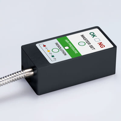
High-precision seating confirmation of workpiece and jig
- Air Gap Sensor -
you can check not only "presence/absence" but also "adhesion (gap)" at the same time with a repeatability of ±0.5μm.
Click here ›What Is Broaching? A Method for Machining Internal Features and Surfaces
Broaching is a process that uses a long, stepped cutting tool called a broach to cut features such as grooves, keyways, and polygonal holes on internal surfaces or external faces.
A broach is a saw-like tool whose cutting edges increase step by step. By pulling or pushing it through in a single pass using a press or similar machine, you can form the desired shape. It is used, for example, for internal splines in gears or machining the hex socket in socket-head bolts, and it offers high repeatability for complex cross-sectional profiles.
It is performed on dedicated pull-type or push-type broaching machines. Although initial tool fabrication costs can be high, broaching is highly productive for repeat parts.
What Is EDM? A Guide to Localized Metal Melting and Removal
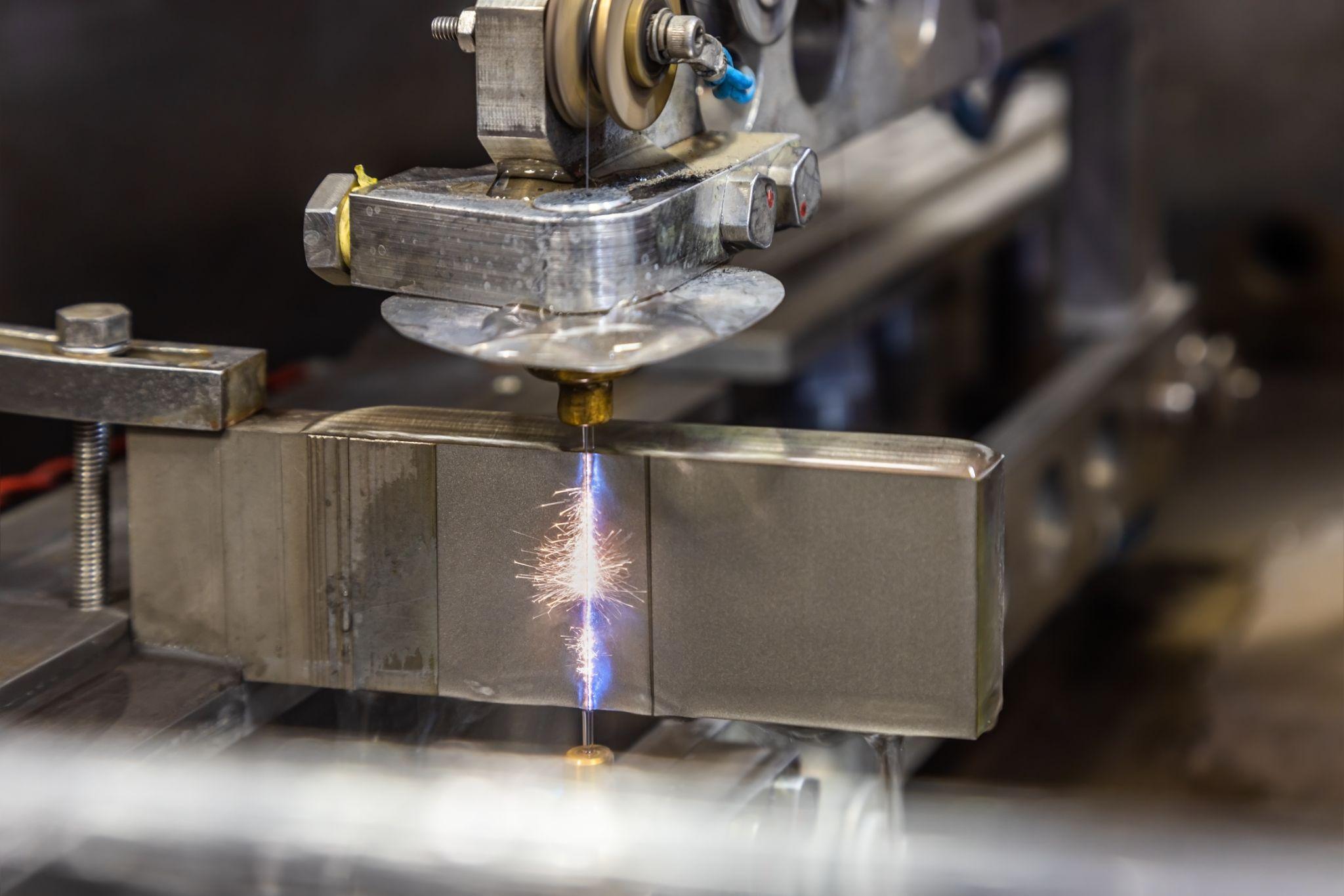
EDM is a non-traditional machining method that locally melts and removes metal using the energy of electrical spark discharges. A discharge occurs between an electrode and the workpiece, and the workpiece is removed through the accumulation of microscopic discharge craters.
It can machine very hard metals and complex geometries, and is well suited for creating sharp internal corners and fine grooves.
Approaches include sinker EDM, where the tool electrode is shaped as a negative (inverse) of the target geometry to reproduce that shape on the workpiece, and wire EDM, which uses a wire electrode to cut out contours.
However, the workpiece must be electrically conductive. Also, because dielectric fluid is circulated through the discharge gap, the machining speed is generally slower than cutting.
What Is ECM? Shaping Metal Using Electrochemical Dissolution
ECM is a machining method that removes metal by electrochemical dissolution rather than electrical discharge.
An electrolyte is flowed between the workpiece and the electrode, and an applied potential dissolves the metal surface to form the desired shape. The tool electrode can be a simple geometry, and even complex shapes can be produced by “tracing” the electrode, making ECM suitable for smooth curved surfaces and fine-hole machining that can be difficult for other methods.
It is a cold process with no cutting force or heat-affected zone, and is used for difficult-to-machine materials such as nickel alloys and titanium alloys. Examples include micro-hole machining in jet engine components and mirror finishing of mold cavities.
However, ECM requires dedicated power and electrolyte systems, and environmental considerations such as post-process electrolyte treatment are also necessary.
Design Tips for Successful Machining: Materials, Geometry, Accuracy, and Heat Treatment
To consistently produce high-quality parts economically through machining, it is crucial to consider manufacturability from the design stage.
Here we explain key design points for machining, including material selection, geometry design, specifying accuracy and tolerances, and planning heat treatment.
How to Choose Materials That Machine Well and Stay Durable: Balancing Machinability and Strength
A part’s material must meet the required strength and durability, but it also needs consideration for machinability.
In general, higher-strength materials also have higher hardness and are more difficult to machine, which increases tool wear and breakage as well as the time required for machining.
Therefore, designers should avoid materials that are harder than necessary and select the best material condition that achieves the required strength after machining.
For example, when selecting a heat-treatable alloy steel, one approach is to procure it in an annealed (softened) condition for machining, and then heat-treat it at the end to reach the required hardness.
If a high-alloy steel is selected without annealing, machining becomes difficult and costs can rise significantly, so be sure to consider whether pre-treatment is needed when choosing materials.
Some aluminum alloys offer higher machinability than steel even with moderate strength, which can significantly reduce machining costs. Another option is free-machining steel (steel with additives such as sulfur or lead to improve machinability).
However, depending on the added elements, abnormal tool wear may occur, so selecting the optimal material requires considering both material properties and machinability.
Designing Machinable Geometry: Practical Ideas to Prevent Machining Issues
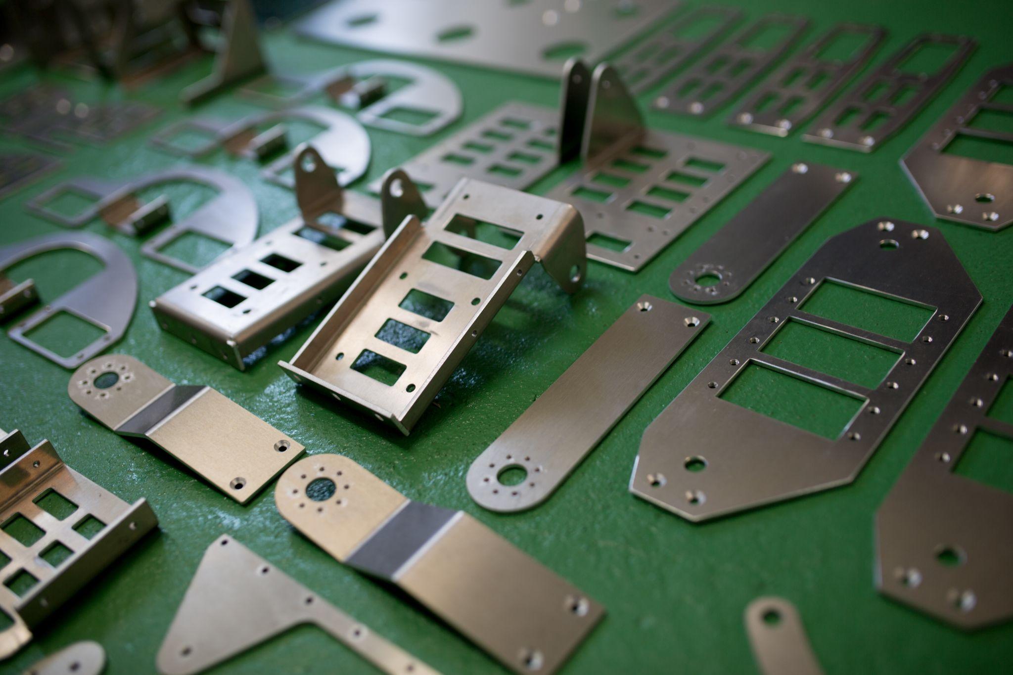
Designers are expected to understand which geometries are easy or difficult to realize with machining and reflect that knowledge in their designs.
For example, perfectly sharp internal corners cannot be machined with rotary tools, so a certain radius (fillet) will always remain.
Accordingly, pockets and slot corners should be designed with as large a corner radius as possible.
A larger corner radius allows the use of larger-diameter (more rigid) tools, enabling faster and more stable machining than cutting a small radius with a slender, long-reach tool.
For instance, if an R5 mm corner radius is acceptable, the pocket can be machined quickly with a 10 mm end mill. But specifying R1 mm may require repeated passes with a tool of 2 mm diameter or less, driving up machining time and cost. In this way, thoughtful geometry choices at the design stage can significantly reduce machining effort.
Also, make hole diameters and slot widths match standard tool sizes whenever possible. If they align with standard drill and end mill sizes, custom tools may be unnecessary, and both tolerance control and short lead-time production become easier.
Additionally, when a part can be split, consider designing it as multiple components rather than forcing a one-piece machining approach, then fastening or joining them after machining.
In particular, complex hollow geometries and undercuts are often difficult even with advanced fixturing and 5-axis machines. Splitting the design and then welding or bolting after machining can ultimately be more efficient and even improve accuracy.
Ideally, designers should adopt the shop-floor perspective and determine geometry in collaboration with manufacturing teams.
Tolerance Basics Every Designer Should Understand
Part drawings specify dimensional tolerances and geometric tolerances (GD&T), and it is important to indicate accuracy that is necessary and sufficient. In machining, when nothing is specifically called out, general tolerances such as ISO 2768 are often applied at a medium level (for example, around ±0.1 mm).
However, tighter tolerances increase machining effort and drive costs up sharply, so tolerance decisions require careful judgment.
For that reason, it is recommended to apply tolerance callouts only to critical features and allow general tolerances elsewhere. If strict tolerances are applied indiscriminately to every dimension, machining and inspection time and cost can become excessive, negatively affecting price competitiveness and lead time.
The basic principle of tolerance design is: “Specify required accuracy only where it affects function, and keep everything else looser.”
For example, assign appropriate tolerance grades to mating holes and shafts, threaded portions, and fits, while using looser tolerances or general tolerances for items such as frames and mounting holes.
In this way, designers balance performance and cost while ensuring the required quality level.
How to Incorporate Quenching and Tempering into Design
As mentioned in the materials section, heat treatments (such as quenching and tempering) that increase hardness and strength require careful planning in relation to machining.
In general, if heat treatment is applied after machining, hardening can cause distortion and dimensional changes, and even carefully finished dimensions may shift due to thermal deformation.
For parts requiring high precision, drawings may need to specify grinding or finish machining after quenching.
Another approach is to harden the material before machining (machining quenched-and-tempered steel or hardened steel directly). However, the material becomes hard and tough, making cutting difficult and requiring special tools and low cutting speeds. This can increase machining time and cause severe tool wear.
Given these trade-offs, designers should plan from the outset “when to apply heat treatment,” and “how far to achieve dimensions by machining versus switching to finishing processes such as grinding.”
For mold and die components, a common approach is to perform roughing through semi-finishing in a softer condition and then carry out finish grinding after quenching.
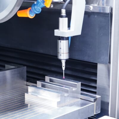
Automated workpiece centering and positioning
- Touch-probe -
a contact/touch sensor for on-machine measurement that improves the efficiency of setup work
Click here ›Improving Mechanical Design and Machining Efficiency Based on Shop-Floor Experience
As described above, machining operations, design, and assembly must work closely together to produce products that justify their costs.
Below are a few examples of efficiency improvements.
For Heavy Material Removal, Consider Using a Different Tool on Purpose
In pocket machining with an end mill, it is common to use an end mill whose radius matches the specified corner radius. The smaller the radius, the more tool paths are needed, and cutting speed cannot be increased easily.
As a result, machining takes longer and throughput per hour becomes limited.
What matters in pocket machining is producing a recess with the specified shape and size—there is no absolute requirement that it must be done using only an end mill.
Roughing a pocket can be dramatically sped up by using a flat-bottom indexable-insert drill. A drill can generate a large volume of chips in a relatively short time, making pocket roughing faster.
In addition, because chips evacuate more easily due to the tool characteristics, issues like “chip packing deep inside the pocket,” which can occur with end milling, are less likely—reducing the risk of tool breakage.
After that, you can finish by tracing the pocket with the end mill that matches the specified corner radius, and the machining is complete.
This is one example that shows how “breaking away from fixed assumptions” can be the first step toward improving machining efficiency.
Improve Productivity with Fixture Design That Matches the Operator’s Posture
Many fixtures used on the shop floor are designed with considerations such as minimizing wasted mounting positions, placing workpieces to avoid dead space, and maximizing the number of parts within the machine’s usable envelope.
However, efficiency cannot be improved if ease of loading and unloading is neglected. Awkward postures reduce concentration and can lead to unexpected mistakes.
In fact, the most common reason behind accidents caused by insufficient clamping or improper mounting was simply “a lack of concentration.”
Designing fixtures that enable stable, high-volume production of precise products is important, but fixture design that considers working posture is also a key factor in improving focus and productivity. When designing fixtures, visualize how the operator will actually work.
Also, if designers periodically join shop-floor work, they can observe realities that are hard to learn from discussions or documents, enabling more practical thinking and designs grounded in real operations.
Tool Manufacturer Information Can Also Lead to Better Efficiency
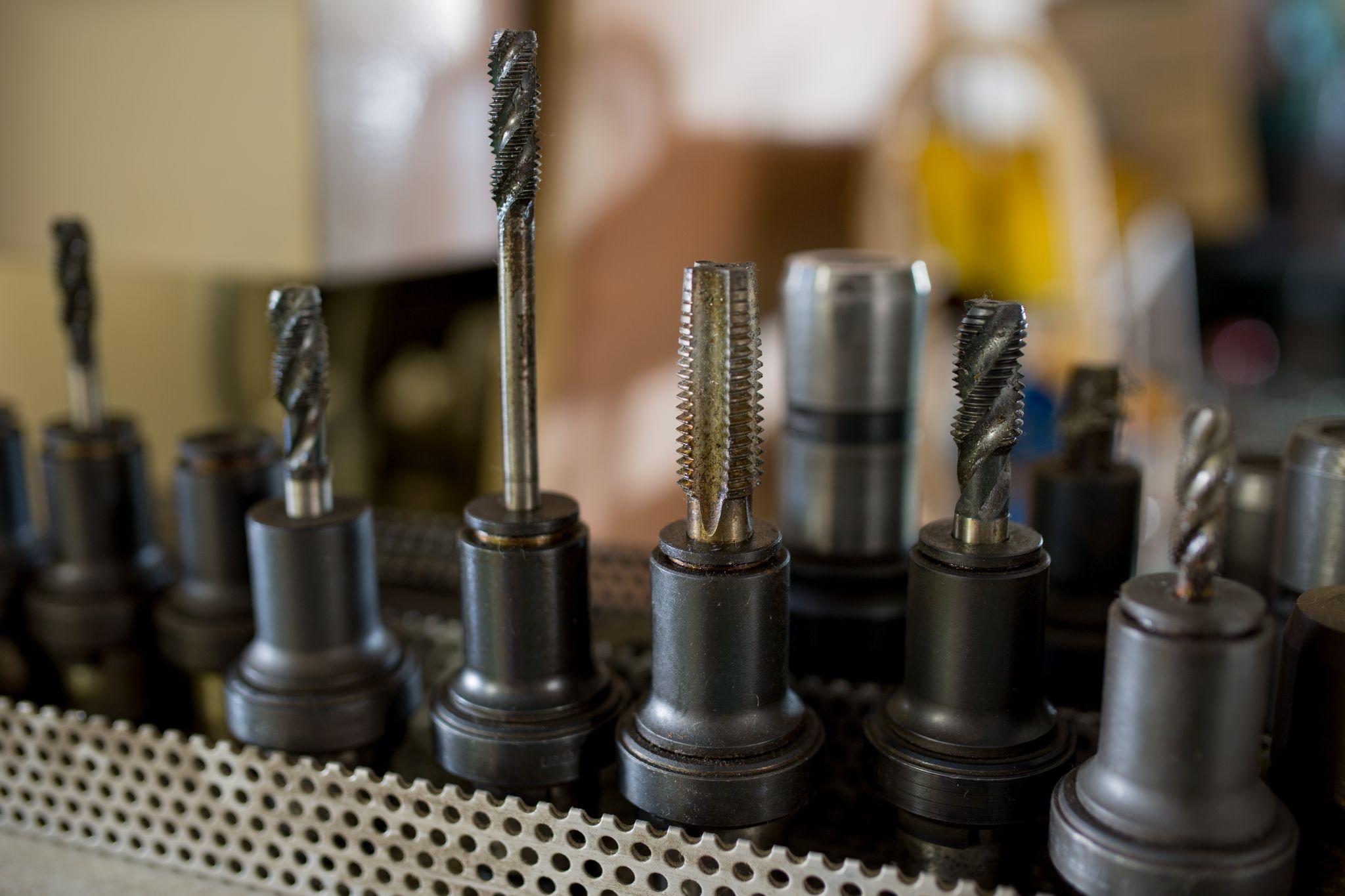
Today, tool manufacturers continually devise and develop tools with efficiency as a key concept, enabling productive machining with tools and methods that were previously hard to imagine.
For example, conventional reaming used to involve steps such as:
- Spotting with a center drill
- Drilling a pilot hole
- Chamfering the hole
- End milling
- Reaming
These were performed as a sequence of separate operations.
Now, “mill-reamers” that have end-cutting edges at the tip are available, making it possible to eliminate the end-milling step.
In addition, burnishing drills can produce holes comparable to reamed finishes using a single tool, completing high-precision hole machining while omitting spotting, pilot drilling, end milling, and reaming. Today, such tools are increasingly common.
However, even if these tools are widely available, not knowing about them makes them effectively “nonexistent,” and true efficiency improvements will be difficult to achieve.
To learn about the latest tools, information from tool manufacturers is essential—but the first step is to question current machining methods. Without asking any questions, you won’t even reach the starting line for improvement.
Not being satisfied with the status quo, raising questions, and proactively taking action are the first steps toward improving machining efficiency.
What Are Metrol’s High-Precision Positioning Sensors?
In machining, accurately positioning the workpiece is essential for improving machining accuracy.
Sensors play a critical role in detecting distance to targets and efficiently positioning workpieces. Whether you can align the tool tip and the workpiece exactly as intended—down to the micron level—has a major impact on quality, yield, and productivity.
Here, we introduce Metrol’s sensor products, offered by a specialist manufacturer that supports high-precision positioning.
High-Precision Positioning Touch Switches
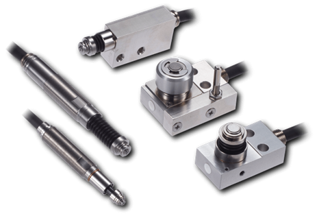
These are contact-type high-precision switches used for positioning and workpiece presence detection in machine tools, robots, and jigs. They achieve an extremely high repeatability of up to 0.5 µm and feature IP67-rated waterproof and dustproof protection, ensuring stable operation even in harsh environments. With more than 200 standard models available, they offer a wide range of variations, including designs for confined spaces, high-temperature environments, vacuum applications, and low contact force requirements.
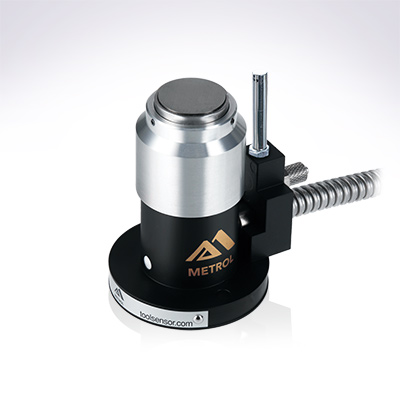
Tool Setter (Tool Length Measurement Sensor)
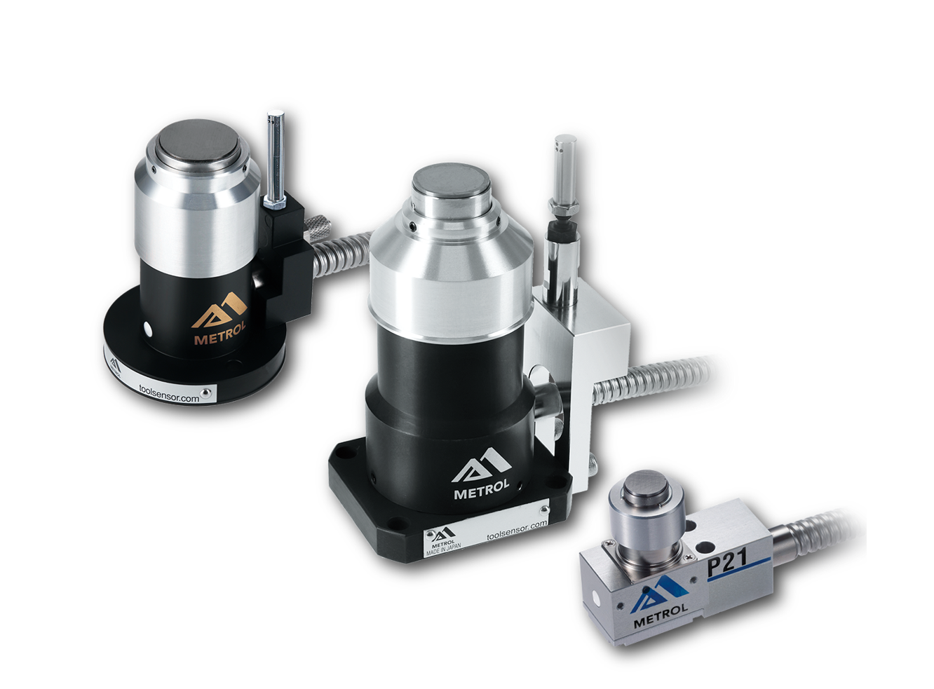
This is a contact-type sensor installed on CNC machine tools and industrial robots for tool length measurement, reference position setting, and tool breakage detection. By automatically measuring and compensating for tool length, wear, and thermal displacement inside the machine, it helps prevent machining defects and significantly reduces setup time. It is one of Metrol’s best-selling products, with a proven track record of more than 500,000 units shipped in 74 countries worldwide.
Touch Probe (On-Machine Measurement Probe)
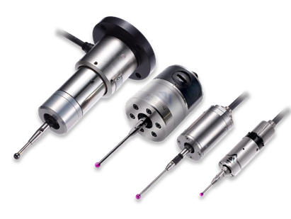
This is a contact-type probe for in-machine measurement, installed on machine tools and robots to automatically perform workpiece positioning (centering) before machining and dimensional measurement after machining. With a repeatability of 1 µm, it automates workpiece referencing and dimensional inspection, replacing skilled manual operations to reduce setup time and help prevent machining defects. Both wired and wireless models are available, meeting retrofit needs for 5-axis machining centers and robotic applications.
Air Gap Sensor (Pneumatic Sensor)
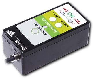
This is a non-contact sensor that uses air pressure to detect workpiece seating conditions with micron-level accuracy. It can detect gaps (“lift”) of less than 10 µm—previously difficult to measure—with a repeatability of ±0.5 µm, helping prevent machining defects and equipment downtime caused by insufficient contact between the workpiece and fixture. The sensor is used in applications such as semiconductor manufacturing processes, precision part clamping operations, and grinding wheel positioning on grinding machines, and it is a smart sensor that also supports the international standard IO-Link communication.