What Is Workpiece Locating? A Thorough Guide from Core Principles to Fixture Design Tips
In machining, accurate processing of a workpiece requires “locating”—holding the workpiece stably at the specified position.
This article explains the fundamentals of locating—such as constraining the six degrees of freedom and the 3-2-1 principle—in an easy-to-follow, diagram-oriented manner so you can hold a workpiece in the ideal orientation and position.
A correct understanding of locating is the foundation for ensuring dimensional accuracy and repeatability.
Table of Contents
Basic Principles of Locating in Machine Tools: A Simple Explanation of 6 DOF and the 3-2-1 Principle
To improve machining accuracy, it is essential to hold the workpiece repeatedly and stably in the correct position and orientation.
This “locating” is achieved by restricting the directions in which the workpiece can move freely—its degrees of freedom.
The starting point is the principle of “constraining the six degrees of freedom.” Any object in space has six DOF: three translations (forward/back, left/right, up/down) and three rotations (pitch, roll, yaw). By constraining them appropriately, you can stabilize the workpiece at the desired position.
Translating this concept into practical design yields the “3-2-1 principle,” a method that uses three types of contact points—on the supporting surface, side surface, and end surface—to locate efficiently and reliably.
In this section, we explain these basic theories and design concepts of locating using diagrams and concrete examples.
What Are the 6 Degrees of Freedom? A Clear Explanation of the Basics of Constraining Workpiece Motion
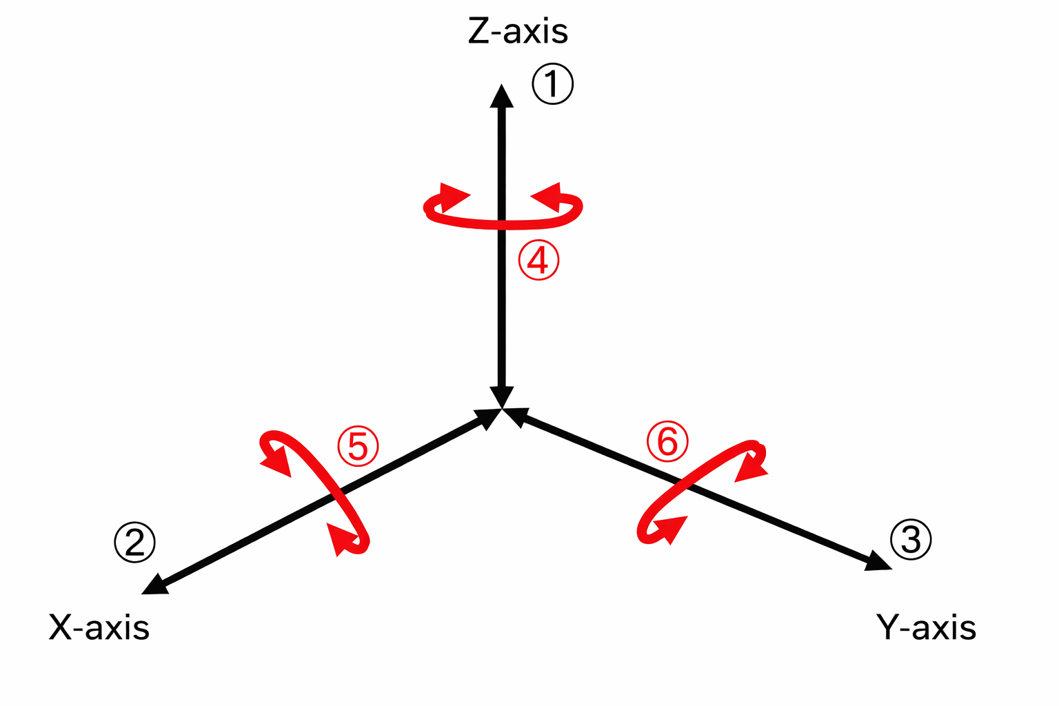
The six degrees of freedom (6 DOF) refer to the six directions in which an object can translate and rotate in space (three translations + three rotations). In locating, all of these must be properly constrained.
When setting a workpiece on a fixture, the goal is to locate it precisely at the specified coordinate position and, at the same time, constrain all degrees of freedom so it does not move from that position during machining.
In general, arranging six support points (locating elements) appropriately is considered sufficient to restrict the six DOF. This is called “six-point support” or the “six-point locating principle.”
Depending on how the six points are arranged, you can achieve either complete or incomplete constraint. If the necessary DOF are not constrained, accuracy cannot be guaranteed. Conversely, if multiple locating elements redundantly constrain the same DOF, unnecessary stress can develop in the workpiece or fixture, potentially causing accuracy loss or deformation.
For this reason, a design that constrains exactly the six DOF using six rigid support points is generally recommended.
What Is the 3-2-1 Principle? A Diagram-Based Explanation of This Fundamental Locating Method
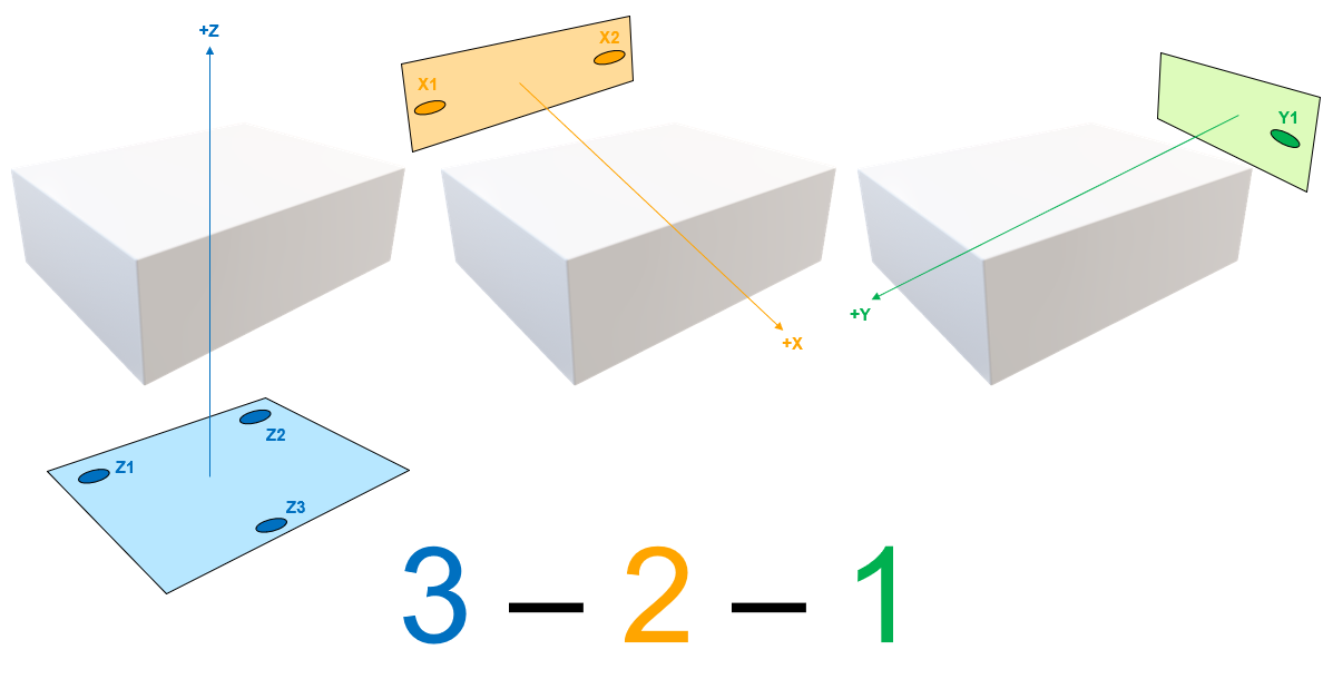
The 3-2-1 principle is a design method for efficiently constraining the six DOF. It achieves stable locating by supporting the workpiece with contact points arranged as 3 points, 2 points, and 1 point.
First, define the primary datum as the Z plane and support it with three points as widely spaced as possible (Z1, Z2, Z3 in the figure) to fix motion in the vertical direction (Z-axis).
Next, locate along the secondary datum on the side of the workpiece (the X plane in the figure) using two points (X1, X2).
Finally, apply one point (Y1) against the tertiary datum on the far side of the workpiece (the Y plane) to constrain the remaining motion.
This constrains all six DOF (three translations + three rotations), achieving locating in which the workpiece position in space is uniquely determined.
In the 3-2-1 principle, a small amount of clearance (an unconstrained DOF) may be intentionally left before clamping to make the workpiece easier to load and unload, improving setup efficiency.
Locating determines the workpiece’s target position, but to prevent shifts caused by vibration or cutting forces during machining, the workpiece must be firmly secured with clamps after locating.
Locating and clamping serve different purposes and functions. Only by designing and operating both appropriately can you achieve stable workholding suitable for precision machining.
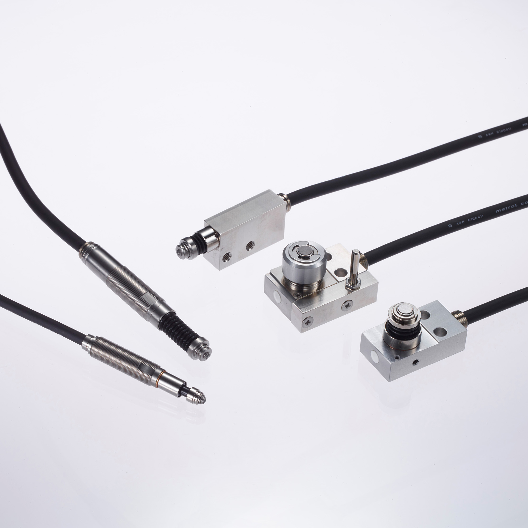
High Precision Positioning
- MT-Touch Switches -
0.5 μm repeatability without amplifier IP67, highly resistant to adverse environments
Click here ›What Are Locators Needed for Fixture Design? Types and Key Design Considerations
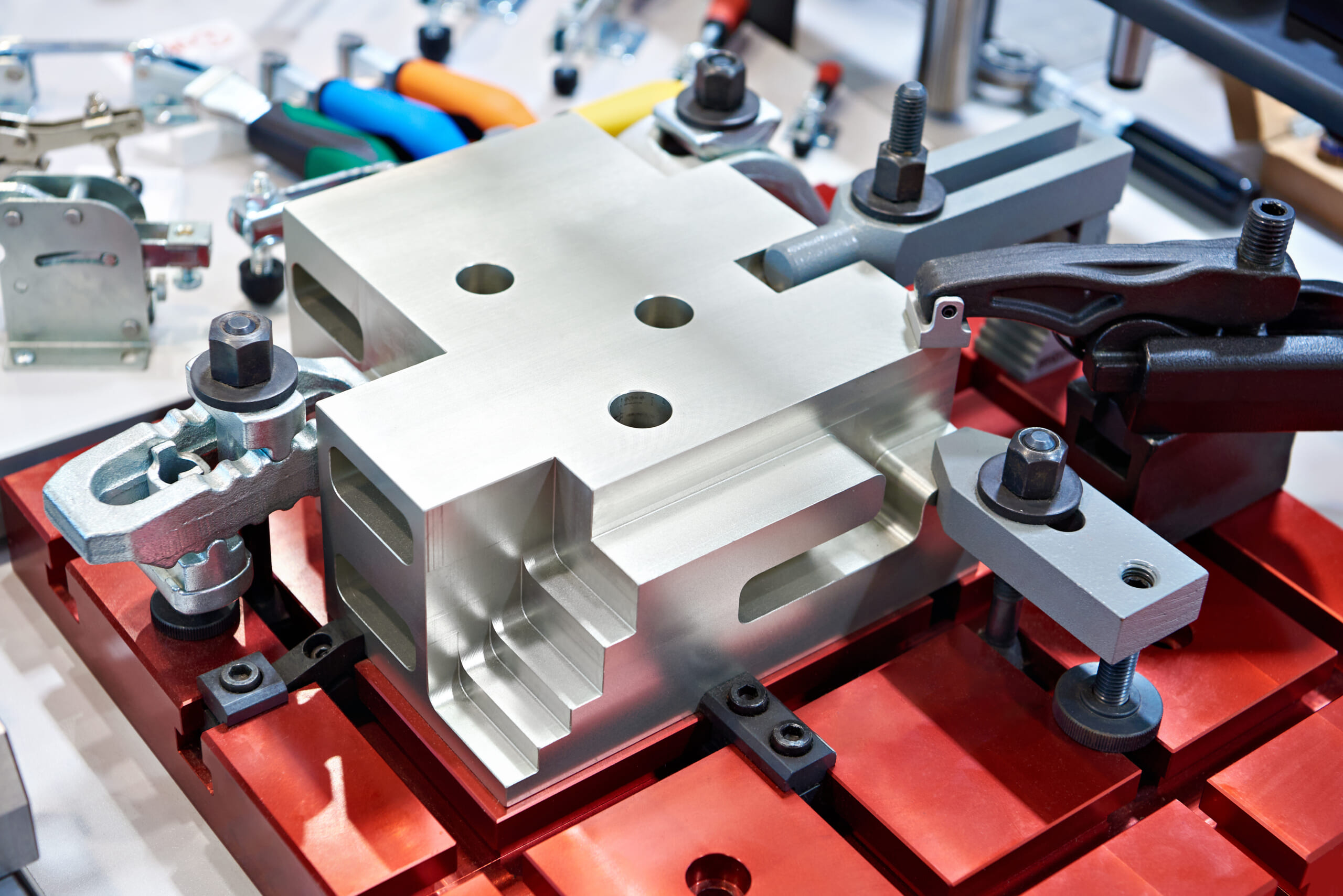
Locators (locating elements) are fulcrums or contact components used to repeatedly and accurately define a workpiece’s specified orientation and position.
Typical locators include support blocks and locating pins, each with variations and design considerations depending on the application.
What Is a Support Block? Roles and Design Tips for a Basic Locator That Stabilizes the Workpiece
A support block is a locator that supports the workpiece from below to locate it in the height direction. It is one of the key factors that influence workpiece stability and machining accuracy.
For a flat, plate-like workpiece, the basic approach is to support it from below with three support points.
These are planar locators that contact the underside as the primary datum surface, typically using rigid locating blocks or height-adjustable supports.
With three fixed supports, the workpiece is stabilized, downward movement is prevented, and the workpiece can be held level.
As a rule, support blocks should contact a “machined, flat surface” to ensure locating accuracy and high repeatability.
What Are Locating Pins? Types and Design Considerations
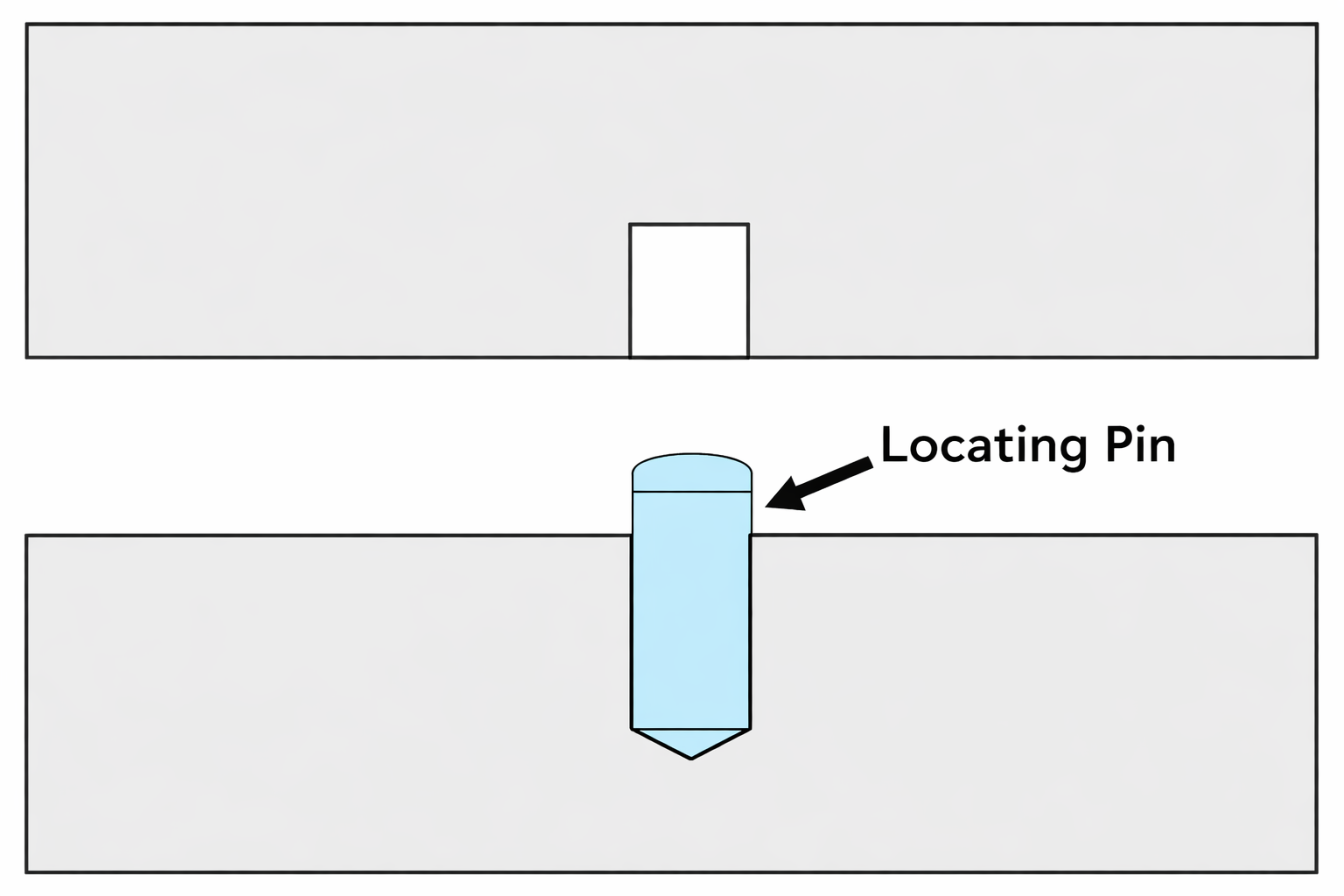
A locating pin is a locator that contacts a workpiece side surface or fits into a hole to constrain degrees of freedom in horizontal directions and rotation. It is a core element in fixture design.
If the workpiece has holes or bosses, locating pins are inserted to align the position.
Pin-type locators provide excellent repeatability, reproducing the same position with high accuracy, and are widely used in fixture-based machining and fixture design.
A common approach uses two pins: one round pin (fixed pin) and one diamond (rhombus) pin.
In this arrangement, the round pin becomes the reference that precisely defines the X and Y position relative to the hole. The diamond pin contacts in only one direction: it defines the position along the remaining axis while providing clearance in the other axis.
This allows smooth insertion even when there are small errors in hole pitch on the workpiece or fixture, while avoiding over-constraint and enabling appropriate, high-precision locating overall.
Other Locator Types and Features: Spring Pins, V-Blocks, and More
Depending on the workpiece geometry, methods other than pins are also used. For example, placing a cylindrical workpiece on a V-block can precisely define its center.
Even for prismatic workpieces, locating may be done by fitting the outer profile into a pocket shape.
With locating based on contact geometry, it is important to consider not only machining accuracy but also part-to-part variation and the influence of burrs; backlash take-up screws or spring pins may be used to accommodate these factors.
In all cases, it is important that locators are made of hard, wear-resistant materials, are replaceable when needed, and incorporate measures to prevent improper contact due to chips or contamination (such as air-blow holes or relief features).
In addition, locating elements must be placed where they can resist the direction of the primary cutting force during machining.
Properly placed locators act as stoppers that receive machining forces and support the workpiece so it does not shift.
What Is Clamping to Secure a Workpiece? A Thorough Guide to Types and Design Tips
Once the workpiece is set at the specified position, it is firmly secured with clamps (clamping devices) so it does not move during machining.
The main purpose of clamping is to keep the workpiece pressed against the previously defined locators, preventing minute shifts or lifting caused by cutting or vibration.
The large cutting forces during machining should, in principle, be handled by supports. Clamps should be designed to (1) keep the workpiece from moving from its located position and (2) suppress lift or kick-up that can occur in the final stage of machining.
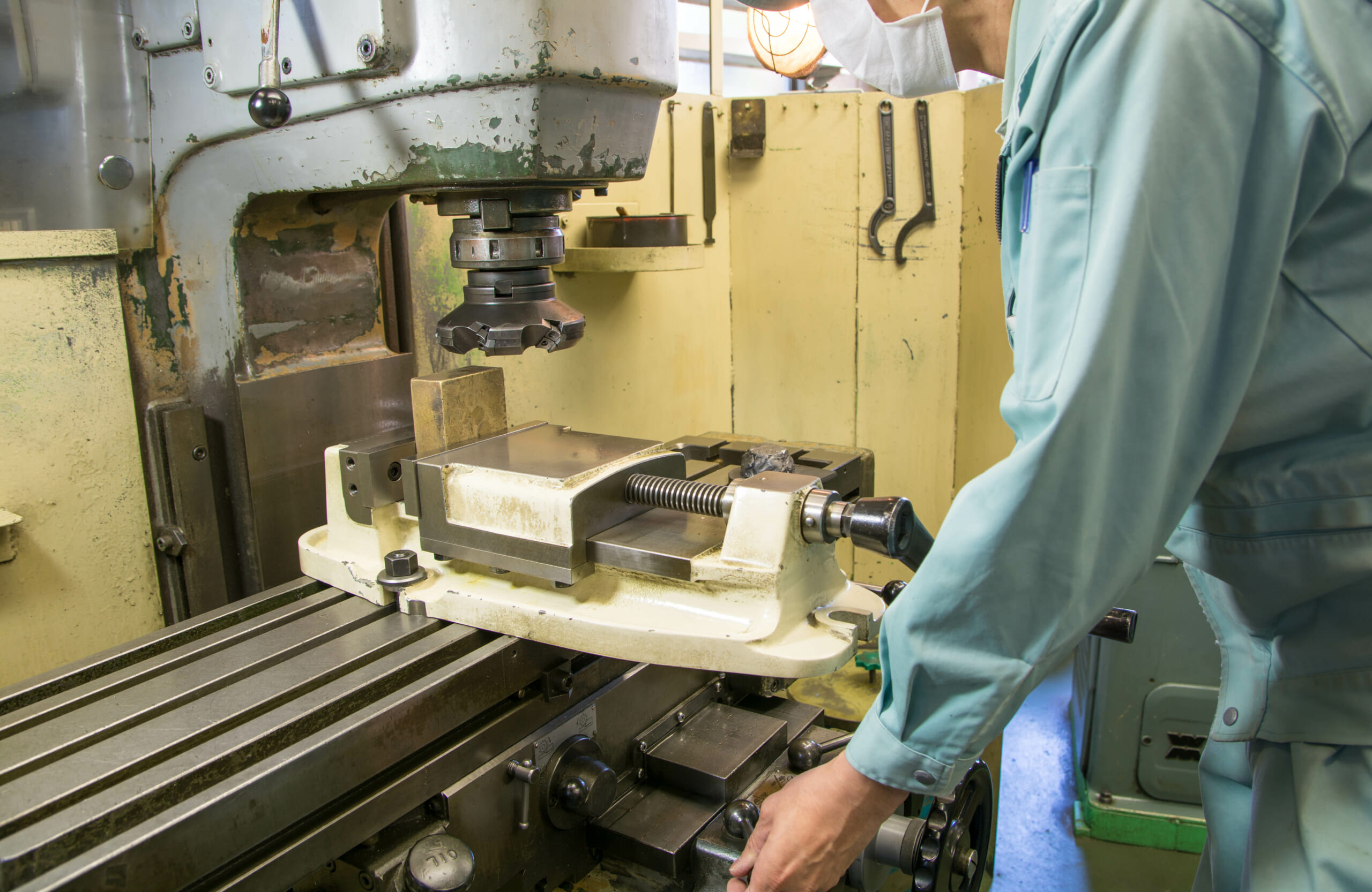
For example, in a milling vise, the fixed jaw side receives cutting forces as a support, while the movable jaw functions as the clamp that presses the workpiece.
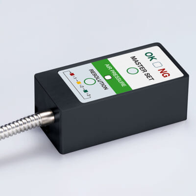
High-precision seating confirmation of workpiece and jig
- Air Gap Sensor -
You can check not only "presence/absence" but also "adhesion (gap)" at the same time with a repeatability of ±0.5 μm.
Click here ›Clamp Types at a Glance: Manual, Hydraulic, Pneumatic, Vacuum, and How to Choose
There are many types of clamps, which can broadly be classified into manual types and powered types.
Manual clamps include screw clamps tightened by a screw, toggle clamps actuated by a lever, strap clamps tightened with bands or bolts, and wedge mechanisms used in vises or dedicated fixtures.
Powered clamps commonly include power clamps driven by hydraulics or pneumatics (hydraulic clamps and air clamps). For special applications, there are also vacuum suction clamps and magnetic clamps using electromagnets.
In automated lines, hydraulic and pneumatic clamps are commonly used and can be operated unattended through machine program control.
Hydraulic clamps provide high gripping force and versatile capability for heavy cutting, but they require higher equipment cost for pumps, piping, and related components.
Pneumatic clamps have lower output than hydraulics but are simpler in structure and are suitable for holding small parts or delicate workpieces (thin plates or soft materials) without damage.
Vacuum clamping is less common in general machining but is effective for holding thin plates by widely suctioning one surface.
For example, for large plates that are hard to clamp around the perimeter, or for workpieces for micro-machining, optimizing the layout of suction ports on a vacuum table can allow multiple shapes to be held without changing fixtures, reducing setup change time.
In many machining shops, it is not uncommon to manufacture in-house fixtures or locating components that are difficult to source as off-the-shelf products.
Below, we explain key points for producing high-accuracy locating fixtures, using an example.
For Cylindrical Work, Machine V-Blocks by Stacking Them Together
As an example, we will explain how to make a “V-block” used in-house to machine cylindrical workpieces.
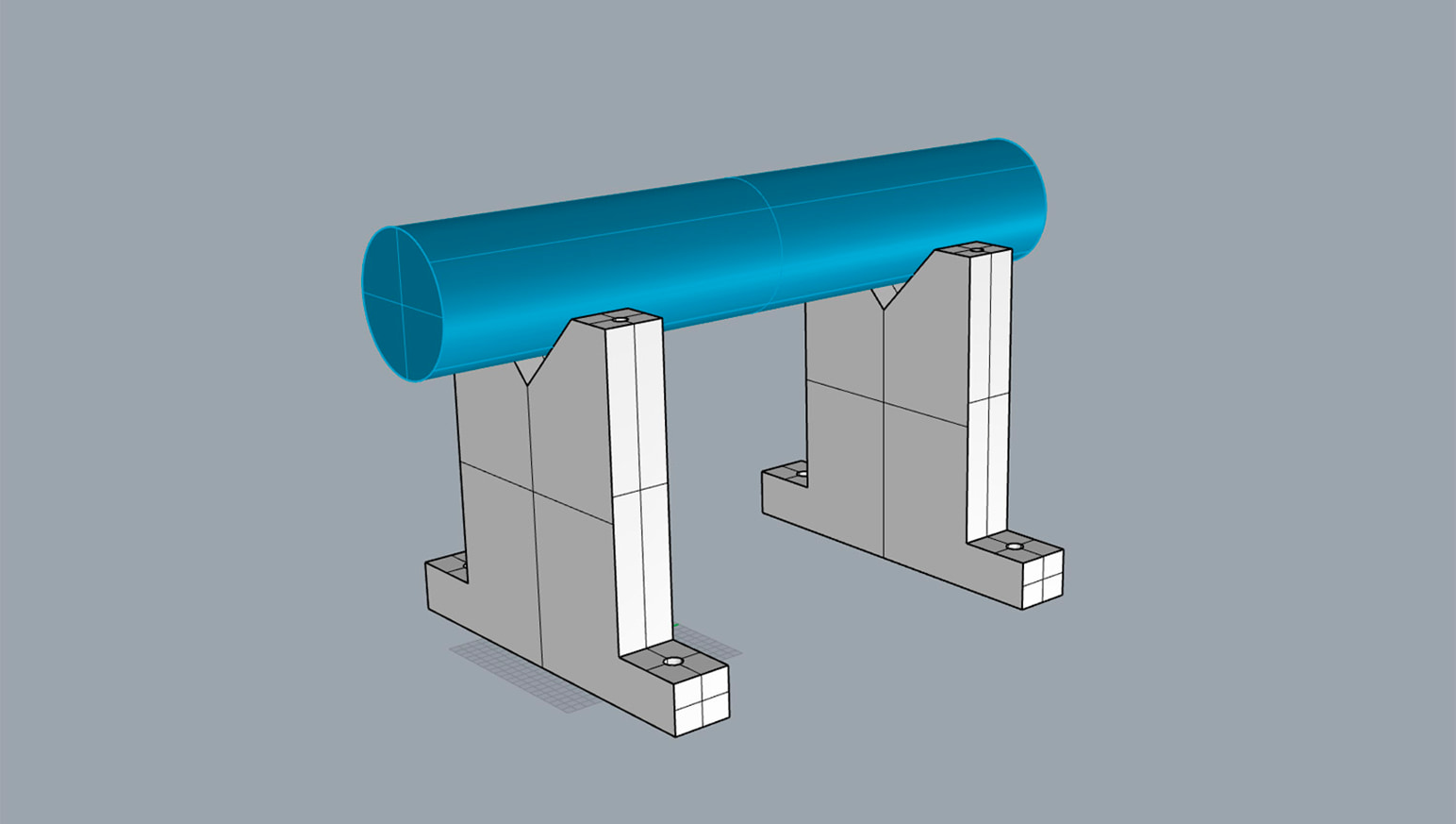
A V-block is a fixture used when performing secondary machining on a horizontal machining center after turning. The workpiece is placed in the upper V-groove to locate it.
Using a V-block keeps the X- and Y-axis coordinates (the workpiece center) constant, making it suitable not only for one-off machining but also for mass production.
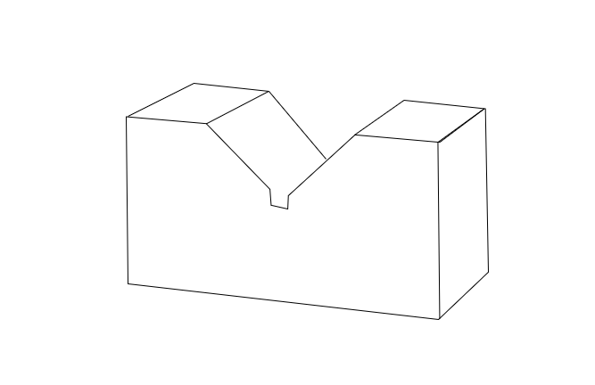
When making V-blocks, stacking two fixtures and machining them together allows you to finish them to the same geometry and accuracy.
Stack the workpieces by welding or bolting them together, then machine and finish the bottom surface and the V-groove in one operation. If you additionally machine a keyway on the bottom surface, you can set the workpiece straight as shown in the figure above.
Also, because the end faces of the V-groove gradually deform (dent) due to clamping and similar actions, allowing a replaceable “hardened and ground plate” to be bolted on helps maintain stable accuracy over the long term.
A Larger V-Groove Angle Allows You to Set Larger-Diameter Cylindrical Work
Most V-grooves on V-block locating fixtures are machined to a 90-degree angle because it is easy to manufacture.
As a result, the workpiece size that can be mounted on the V-block is limited to an outer diameter that fits up to the “boundary between the V-groove and the top surface of the fixture.”
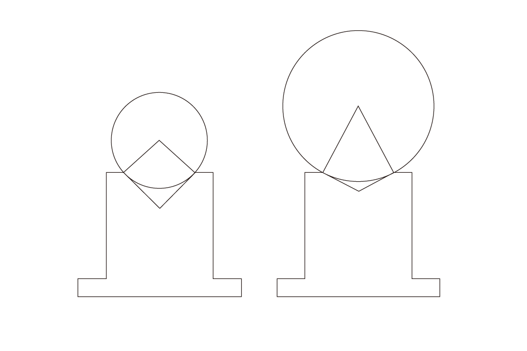
As shown above, the larger (more obtuse) the V-groove angle is, the larger the workpiece you can mount, enabling machining of large-diameter workpieces.
Although you can machine a workpiece larger than the V-block body, depending on the workpiece geometry, it may deform due to the clamping method or clamping force.
In particular, when mounting a thin-walled cylindrical workpiece using the V-block on the right in the figure, the clamping force is distributed along the V-groove faces, making it likely to generate “radial” forces that crush the workpiece from the side toward the center.
An obtuse-angle V-block offers high stability and a wide groove opening, which can make it easier to approach cutting from the longitudinal direction. However, pay attention to risks such as deformation, lower repeatability in centering, and weaker holding due to force “escaping” in the contact geometry.
To determine the mountable size, if the V-groove is a right angle (90 degrees), then “workpiece radius = length of the V-groove slope.”
As in the left figure above, it is easier to understand by considering a square that passes through the V-groove endpoint and the center of the circle.
Precautions When Using Hydraulic and Pneumatic Clamps
The hydraulic and pneumatic clamps described above can improve productivity in automated lines and eliminate human errors such as forgetting to clamp, as long as the machining program includes clamp/unclamp commands (e.g., M-codes).
Hydraulic clamps can deliver large gripping force, but if piping is damaged by chips or a dropped workpiece, circulating oil may contaminate the machine interior and the workpiece.
For products that require “dry machining,” such as plastics, contamination due to “oil leakage from piping” can become a serious problem on the machining line.
Therefore, if possible, it is recommended to route piping away from the workpiece loading/unloading area. With pneumatic clamps as well, take care not to place cylinders and piping used to apply pressure near the loading/unloading space.
What Are Metrol’s High-Precision Positioning Sensors?
In precision machining, even slight positional deviations can significantly affect quality and productivity.
Metrol’s sensors enable stable, high-precision locating in such environments.
With a wide lineup—touch switches, tool setters, probes, and more—matched to different applications, they significantly improve reliability and efficiency in machine tools and automated lines.
Below, we explain the features of Metrol’s representative locating sensors.
High-Precision Positioning Touch Switches
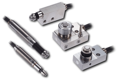
These are contact-type high-precision switches used for positioning and workpiece presence detection in machine tools, robots, and jigs. They achieve an extremely high repeatability of up to 0.5 µm and feature IP67-rated waterproof and dustproof protection, ensuring stable operation even in harsh environments. With more than 200 standard models available, they offer a wide range of variations, including designs for confined spaces, high-temperature environments, vacuum applications, and low contact force requirements.
Tool Setter (Tool Length Measurement Sensor)
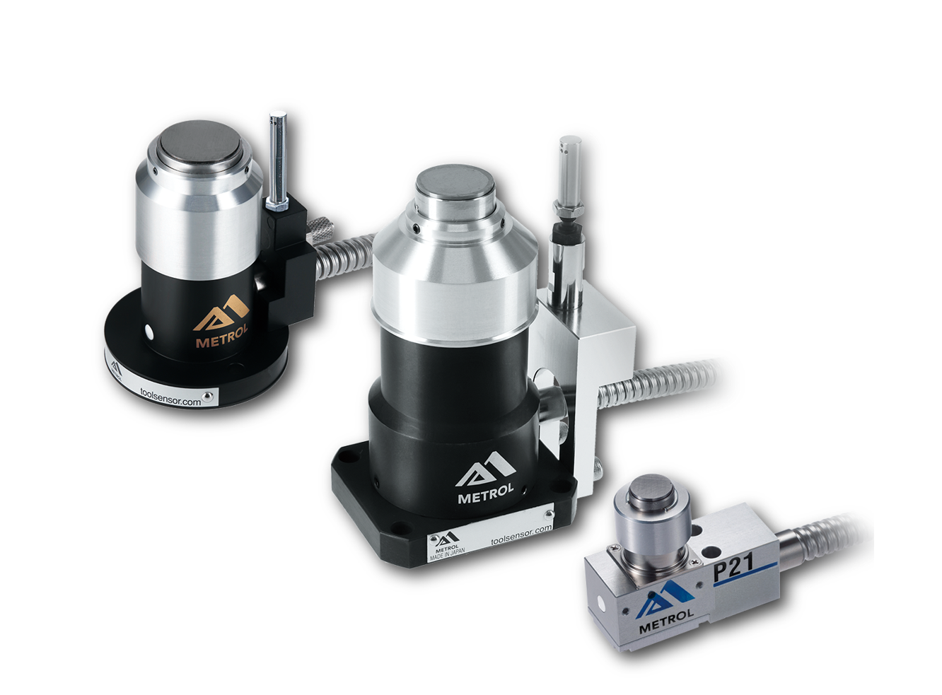
This is a contact-type sensor installed on CNC machine tools and industrial robots for tool length measurement, reference position setting, and tool breakage detection. By automatically measuring and compensating for tool length, wear, and thermal displacement inside the machine, it helps prevent machining defects and significantly reduces setup time. It is one of Metrol’s best-selling products, with a proven track record of more than 500,000 units shipped in 74 countries worldwide.
Touch Probe (On-Machine Measurement Probe)
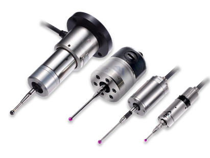
This is a contact-type probe for in-machine measurement, installed on machine tools and robots to automatically perform workpiece positioning (centering) before machining and dimensional measurement after machining. With a repeatability of 1 µm, it automates workpiece referencing and dimensional inspection, replacing skilled manual operations to reduce setup time and help prevent machining defects. Both wired and wireless models are available, meeting retrofit needs for 5-axis machining centers and robotic applications.
Air Gap Sensor (Pneumatic Sensor)
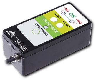
This is a non-contact sensor that uses air pressure to detect workpiece seating conditions with micron-level accuracy. It can detect gaps (“lift”) of less than 10 µm—previously difficult to measure—with a repeatability of ±0.5 µm, helping prevent machining defects and equipment downtime caused by insufficient contact between the workpiece and fixture. The sensor is used in applications such as semiconductor manufacturing processes, precision part clamping operations, and grinding wheel positioning on grinding machines, and it is a smart sensor that also supports the international standard IO-Link communication.