What Is Tool Length Compensation? A Thorough Guide to G-Code Usage, Setup Procedures, and Troubleshooting

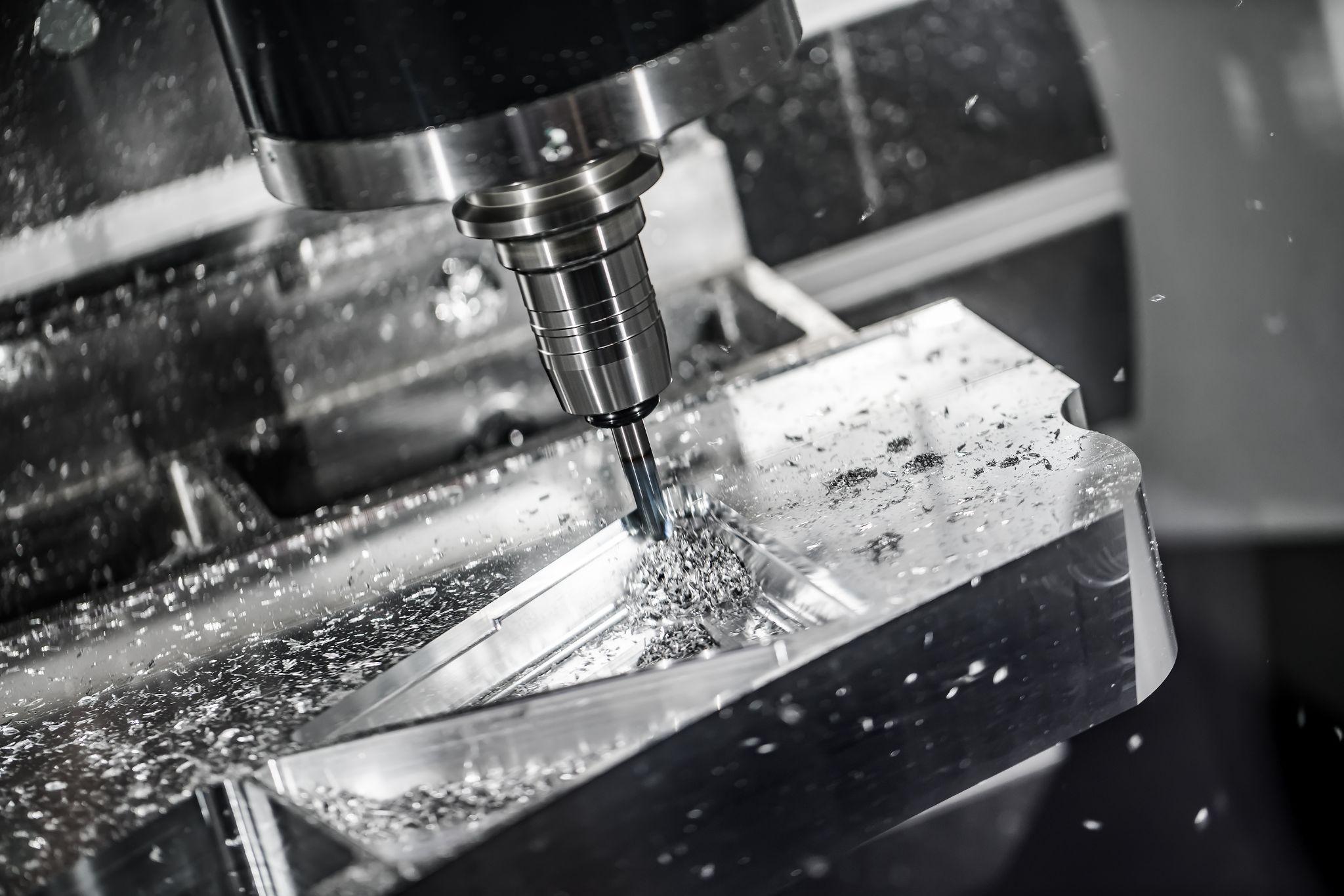
In CNC machining, “tool length compensation” is a critical function that directly affects machining accuracy and work efficiency.
Because tool length varies by tool type and with each tool change, you must accurately compensate Z-axis positioning; otherwise, you risk dimensional defects and workpiece damage.
This article clearly explains everything from the fundamentals of tool length compensation to G-code control (G43, G44, G49), practical setup methods, and common shop-floor issues with proven countermeasures.
From beginners to experienced operators, this guide covers the essential knowledge needed to stabilize day-to-day machining quality.
Table of Contents
What Is Tool Length Compensation? Core Concepts and Definitions for CNC Machining
Tool length compensation is a function that automatically adjusts machine coordinates to account for multiple tools with different lengths.
By compensating machining coordinates based on each tool’s tip position, this function eliminates the need to reset the Z-axis reference point (work origin) in the program every time you change tools.
When tool length compensation is enabled, the CNC machine corrects the Z-axis position so that the “tool tip” becomes the reference.
When compensation is disabled, the machine’s position data is referenced to the spindle nose, which creates a tool-tip position error equal to the tool length. Tool length compensation removes this discrepancy, enabling accurate depth and positioning even when using tools of various lengths.
Why Tool Length Compensation Is Necessary: Objectives and Benefits in CNC
Tool length compensation is indispensable on CNC machine tools equipped with automatic tool changing.
On machining centers, many tools are loaded into a magazine and automatically exchanged via programmed commands; tool length compensation automatically corrects differences in each tool’s effective cutting tip length.
As a result, operators no longer need to re-establish the Z-axis reference point on the workpiece for each tool, enabling continuous multi-tool machining exactly as programmed.
Without tool length compensation, you must reset the Z-axis reference point at every tool change or manually reflect tool length differences in the program—an inefficient approach that also increases the likelihood of accidents.
In other words, the purpose of tool length compensation is to improve machining accuracy and productivity by having the machine manage and correct each tool’s length.
Tool length compensation directly ensures accuracy in the depth direction, preventing depth errors and machining mistakes caused by tool length variation.
It is also a foundational technology for program-based automation of machining sequences that involve tool changes; advanced automated machining (including ATC) is not feasible without tool length compensation.
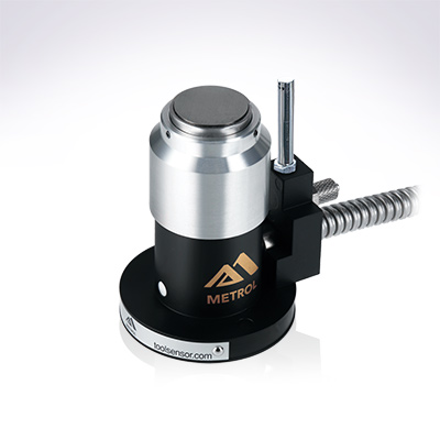
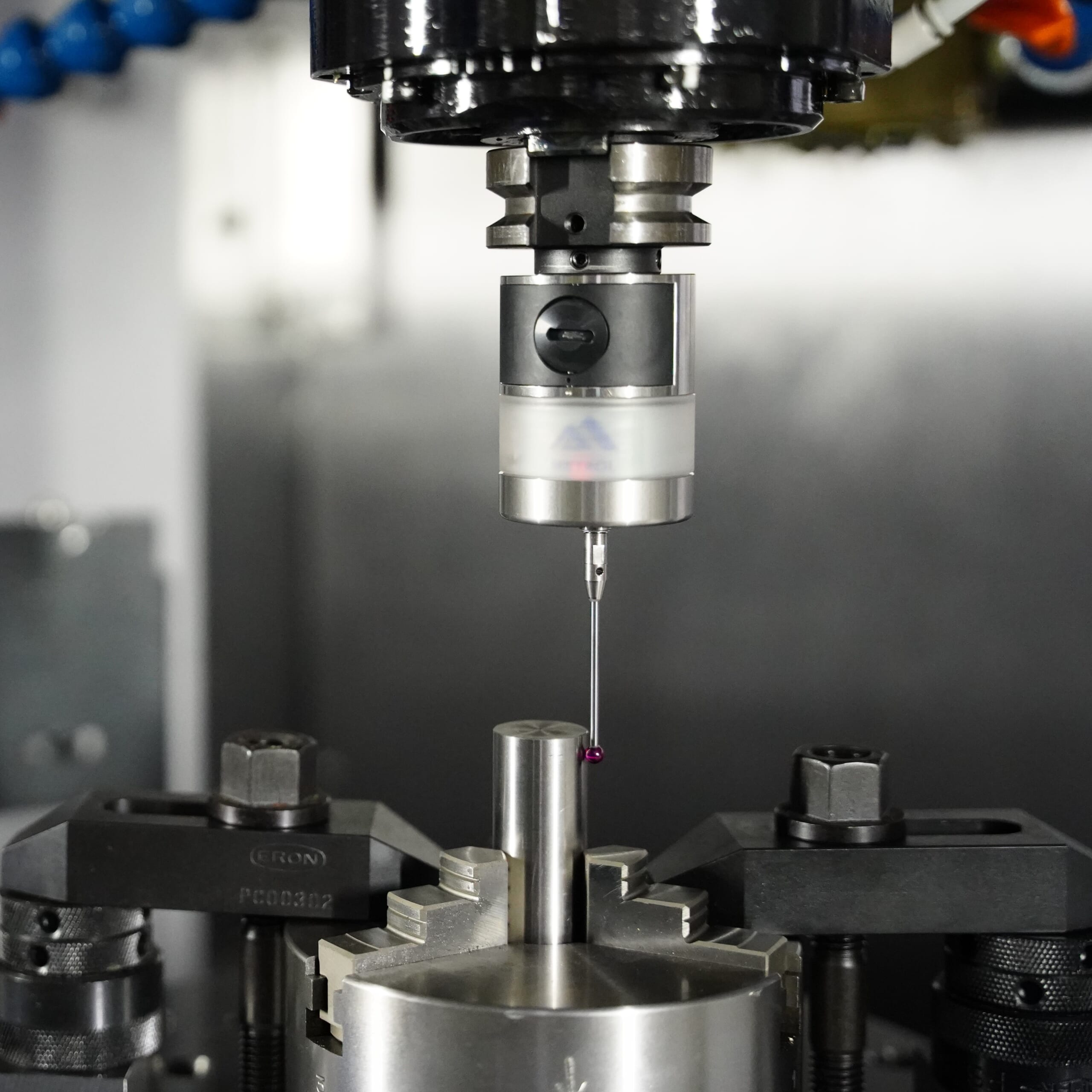
Automates originating of cutting tools
- Tool Setter -
Tool length and chips is monitored to prevent machining defects due to wear and thermal displacement
Click here ›G-Codes Used in CNC: What’s the Difference Between G43, G44, and G49?
| Code | Function | Description |
|---|---|---|
| G43 | Tool length compensation (+) | Compensates in the Z-plus direction by the specified value |
| G44 | Tool length compensation (−) | Compensates in the Z-minus direction by the specified value |
| G49 | Tool length compensation cancel | Cancels the specified tool length compensation |
Tool length compensation is primarily commanded using G-codes.
In milling operations, the primary G-codes are G43, G44, and G49.
You also use the “H address” to specify the tool length offset in the offset table.
Below is an overview of each code’s role.
What Is G43? Meaning and Usage of the Most Common Tool Length Compensation Command
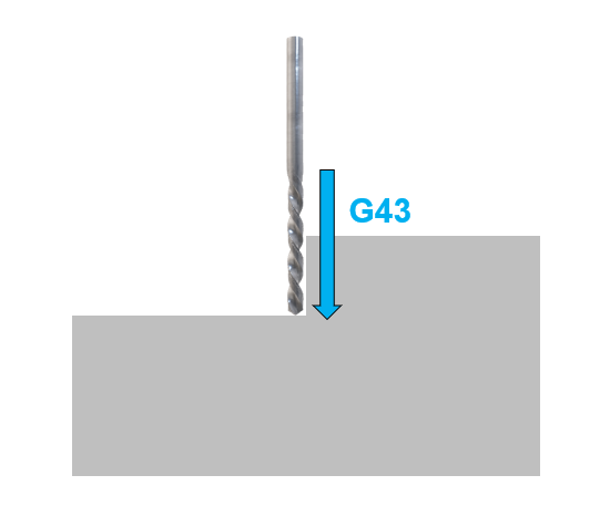
G43 is the most commonly used command for turning tool length compensation on.
The format is “G43 H Z,” which calls the tool length offset for the specified H number and moves while compensating the Z-axis position.
Typically, the H number matches the tool number (e.g., H2 for Tool 2), and the machine reads and applies the tool length that the operator has pre-registered on the tool offset page.
With G43, the compensation value (tool length) is added in the Z-plus direction.
In practical terms, if the tool is longer than expected, the machine offsets coordinates upward so the cutting edge is raised and does not overcut into the workpiece.
In common practice, when the workpiece top surface is set as Z=0, each tool length is registered as a positive value representing the distance from the spindle reference position (gauge line) to the tool tip, and G43 applies that positive tool length offset to the Z axis.
What Is G44? Role and Precautions for the “Minus” Tool Length Compensation G-Code
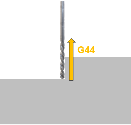
G44 is the opposite of G43: it applies the tool length compensation value in the Z-minus direction.
In other words, it “subtracts” the compensation value, but in real-world machining, G44 is not commonly used.
Most operators use the standard G43 (positive direction).
G44 is mainly used in special cases or on certain older control schemes, and in typical operations you usually don’t need to worry about it.
What Is G49? How to Cancel Tool Length Compensation and Key Precautions
This command cancels (turns off) the currently active tool length compensation.
It is used when you want to cancel tool length compensation in a program, but it is not mandatory in most CNC programs.
On modern CNC machines, executing G43 H for a new tool automatically switches from the previous compensation number.
The compensation state is also typically reset at program end (when M30 is executed).
Even so, as a safety measure, some programs include G49 in the initial (safety) line to ensure compensation is turned off.
Some controllers may have vendor-specific options or derived codes, but the core concept can be understood using G43/G44/G49 and the H number.
Example of Code Usage
Typically, immediately after a tool change (M6), you move the spindle to a safe clearance position above the workpiece and then enable tool length compensation as shown below.
T2 M6 (Change to Tool 2)
G0 G54 G90 X... Y... S*** M3 (Rapid move to X,Y in work coordinate system G54; spindle ON)
G43 Z50.0 H2 (Apply tool length offset #2 and move Z to 50.0 above the workpiece)
... (machining operations follow) ...
In this example, the machine applies H2 for Tool 2 and moves the tool tip in the Z direction to a position 50.0 mm above the workpiece top surface.
Subsequent machining proceeds in a coordinate system referenced to the tool tip.
When switching to the next tool, executing G43 with the corresponding new H number automatically replaces the previous compensation with the new one.
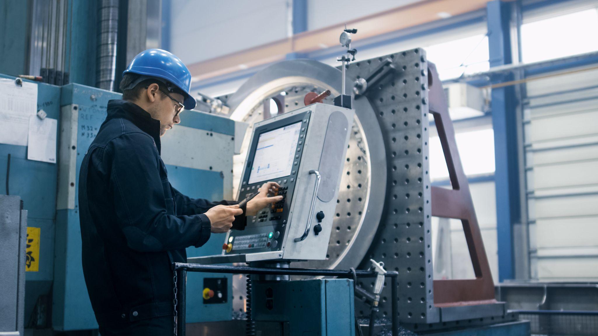
Automated workpiece centering and positioning
- Touch-probe -
a contact/touch sensor for on-machine measurement that improves the efficiency of setup work
Click here ›How to Set Tool Length Compensation on CNC: From Basics to Practical Applications
Tool length compensation values (tool length offsets) are registered on a per-machine basis.
When measuring tool length with the tool mounted in the spindle and entering the measured value into the corresponding tool number’s offset, there are two common measurement methods:
Tool Length Compensation Based on the Gauge Line: A Practical Method for Standardizing Across Machines
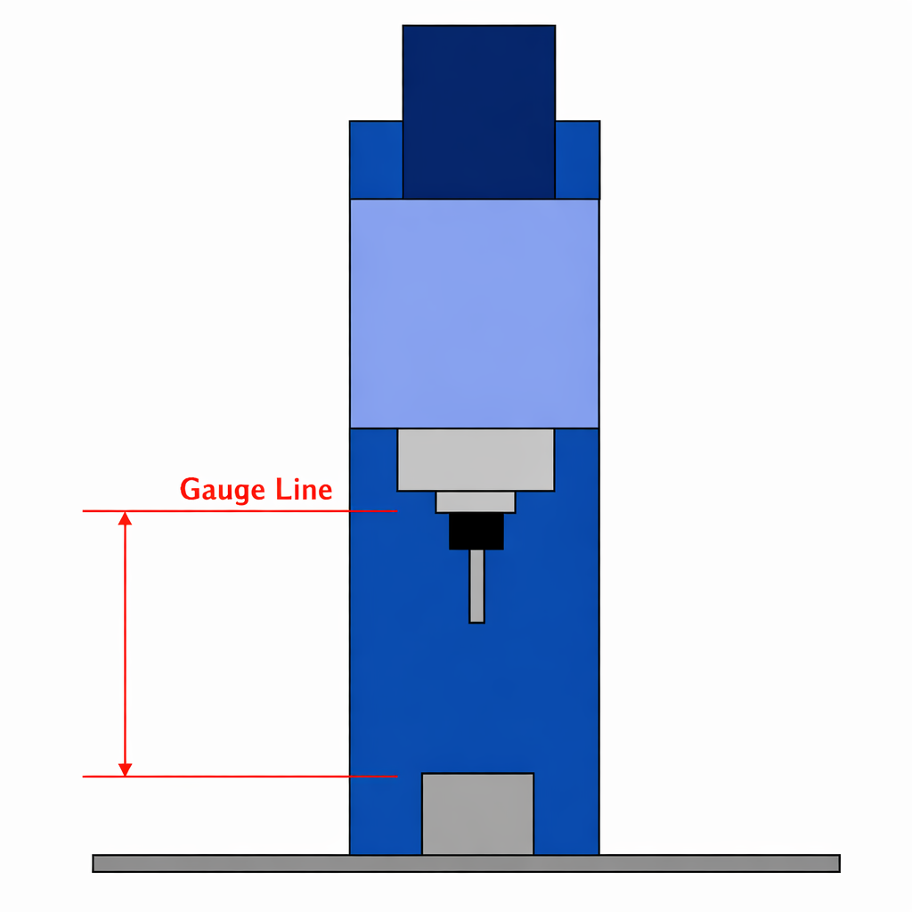
This method measures the absolute length from the spindle reference surface (the gauge line, typically the spindle face) to the tool tip, and registers that value directly as a positive tool length offset.
It is used when entering values measured by a tool presetter or when automatically measuring tool length using an on-machine tool setter.
Its advantages are that the measurement reference can be standardized across machines—so the same tool length offsets can be reused on multiple machines—and machining can begin immediately after a tool change.
With this approach, the Z offset value in the work coordinate system on the machine (e.g., the Z value in G54) tends to be negative because the workpiece top surface lies below the gauge line.
Tool Length Setup Based on the Workpiece Top Surface: How to Use Negative Offsets
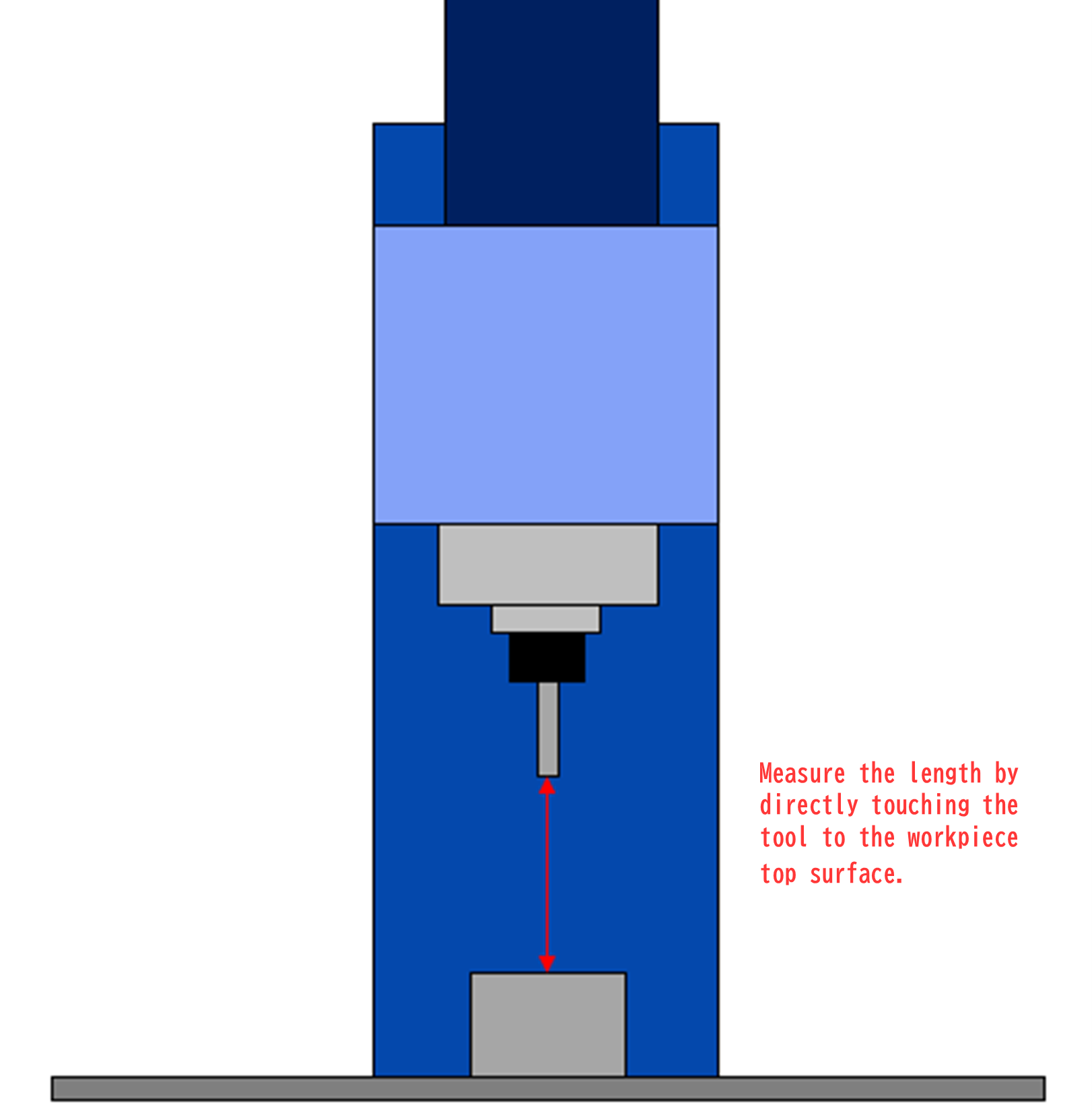
With the workpiece-top reference method, you touch each tool directly to the workpiece top surface to measure its length and register the difference from that work reference as a negative value in the tool offset.
In this case, the distance from the work coordinate system’s Z zero to the tool tip becomes the offset value, so the workpiece top surface remains Z=0 and tool length offsets are recorded as negative values.
This method has been widely used on older machines and in manual-centric shops. Its advantage is simplicity: even without specialized measuring equipment, you can set offsets by touching the tool to the workpiece and pressing the offset measurement button.
On the downside, you must remeasure all tools whenever the workpiece height changes, and you cannot easily reuse tool offsets across multiple machines.
As an intermediate approach between the two methods above, you can also touch off on a block of known height, such as a gauge block.
For example, you can measure each tool by touching it to a 100.00 mm-high block placed on the table and register each tool length offset as a negative value referenced to the block’s top surface.
Then, by adding the block height (100.00 mm) to the work coordinate system’s Z offset, you can manually operate in a way that closely resembles the gauge-line reference method.
With this method, you can set tool offsets without having to skim-cut the workpiece to create a flat reference each time, and because each tool’s offset remains consistent, you can significantly reduce job-by-job setup work.
Common Tool Length Compensation Mistakes and Countermeasures: Pitfalls CNC Beginners Should Avoid

A basic mistake with tool length compensation is “forgetting to include the tool length compensation command in the program.”
For example, if you start machining after a tool change without executing G43 H…, the machine may continue moving with the previous tool length compensation still applied. This can cause deeper-than-intended cutting that damages the workpiece, and in the worst case can lead to tool breakage or machine damage.
If the previously used tool is longer than the current tool, collision risk may be lower, but the current tool may not reach areas that should be machined, leaving stock uncut. The next tool can then collide with this unmachined area, potentially damaging the tool or the machine.
Even experienced machinists can make this mistake, so countermeasures include always placing the “correct H number and G43 command” at the beginning of the program and retracting to a sufficiently safe Z clearance height during tool approach.
It is also recommended to incorporate a “Z height check” for safety confirmation.
After stopping the spindle, if you can verify with a 100.00 mm block that the distance between the tool tip and the workpiece top surface is exactly 100.00 mm, you can confirm that both the tool length offset and the work origin setting are correct.
If the height does not match, it indicates a setup error somewhere—correct it before starting machining.
Making it a habit to use a Z-axis safety line helps prevent not only workpiece and tool damage but also collisions with clamps and fixtures.
Another point to note is that you must be careful when using the G49 (compensation cancel) command.
This is because, depending on the machine, executing G49 can cause the spindle reference point to shift abruptly by the tool length from the current position.
For instance, if you command G49 during machining with a tool, the machine recognizes “no tool length compensation,” which can cause an instantaneous Z-axis movement and lead to a collision with the workpiece.
Therefore, as a rule, use G49 only in safe situations—such as at the end of the program or before/after tool changes (machine home or ATC home)—and do not cancel compensation carelessly mid-cut.
Originating the blade of CNC Lathe
- Tool Setter -
performs wear, chipping, and thermal displacement compensation, contributing to maintaining the constant machining precision of the machine tool
Click here ›Real-World Examples of Tool Length Compensation Based on Shop-Floor Experience
Tool length compensation is essential on machining centers equipped with ATC (Automatic Tool Changer) functionality.
To take full advantage of this function and improve machining efficiency, you need accurate tool length management and effective use of machine reference (home) positions.
Below are practical methods and examples of using “tool length compensation” and “machine reference points” for machining on horizontal machining centers.
How to Work Effectively When You Only Have an Aged or Low-Accuracy Tool Presetter
Tool presetters are widely used in many shops, but it’s not uncommon to see facilities continuing to use units that can no longer achieve accurate measurement due to years of use, damage, or deterioration.
One reason these issues are often left unaddressed is that tool presetters are relatively expensive, and management (owners) may view the equipment as not directly impacting productivity—making cost sensitivity a major barrier.
Even in such conditions, if you need to continue producing high-precision, accurate parts, you should learn a tool length measurement method based on the machine reference point.
On many horizontal machining centers, the X and Z axes are referenced to the center of the pallet, and the Y axis is referenced to the top surface of the pallet. For tool length measurement, you use the Z reference value.
Set the workpiece at the center of the pallet and set the machining origin to the “machine reference point (Z-1000.000).”
Next, machine two faces at 0° and 180° at the same Z-axis value using an end mill or similar tool. Measure the machined dimensions; half of the deviation between the target dimension and the actual machined dimension is used as a compensation value, yielding an accurate tool length compensation value for that end mill relative to the machine reference point.
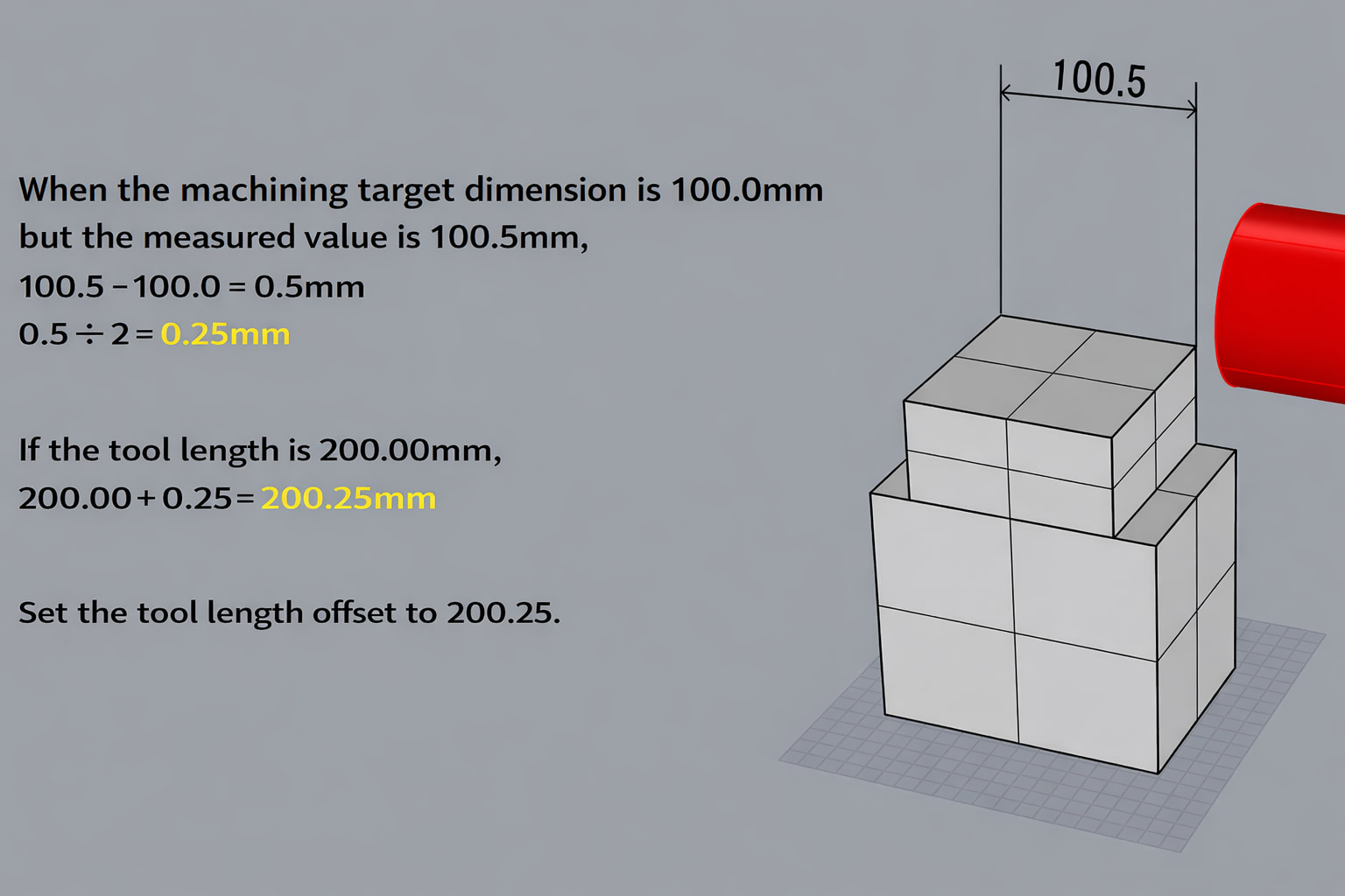
At this time, it is recommended to preload a program such as “G43 H*** Z200.0,” because the value shown on the monitor becomes “the value from the configured machine reference point,” making the work easier.
This method can produce more accurate tool length results than measuring with an aged tool presetter, but to maintain the machine’s accuracy, use a test bar or similar method and perform periodic accuracy checks.
For Fixed or Common Tools, Register Accurate Tool Length Offset Values
For fixed tools or common tools used on horizontal machining centers, it is necessary to align and register accurate tool length compensation values for each tool.
For example, if the tool lengths of a φ80 face mill and a φ160 face mill deviate from their correct values, it can severely impact machining accuracy and cause a large number of defective parts.
As an example, consider machining an O-ring groove with a specified “groove depth of 2.5 mm ±0.05.”
If Product A uses a φ80 face mill and Product B uses a φ160 face mill, and both are machined with the same O-ring groove cutter, the groove depth accuracy will not be achieved unless both tools’ length values are entered accurately.
Even if Product A (using the φ80 face mill) meets the groove depth specification, Product B (using the φ160 face mill) may not—resulting in grooves that are too shallow or too deep.
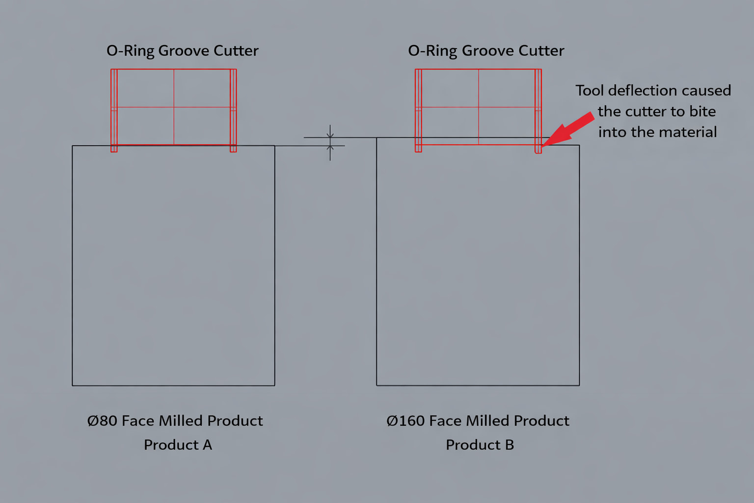
In the figure above, because the φ160 face mill’s tool length has not been measured accurately, the O-ring groove cutter is digging into the workpiece.
Moreover, if you “change the O-ring groove cutter’s compensation value” because “Product B is not meeting dimensions,” you may then cause Product A to go out of tolerance.
In the case shown above, the O-ring groove on Product A becomes shallower.
Even if it takes effort, measure and register accurate tool length compensation values for fixed or common tools.
Entering accurate tool length compensation values makes it easier to achieve dimensional accuracy when machining at an angle by changing the pallet orientation or when machining from both sides, and it can also reduce the total time from setup through mass production.
If a tool has an accurately measured tool length compensation value, you can use the same value on other machines as well, helping reduce dimensional variation caused by transferring machining fixtures.
Of course, adopt this approach only after performing the previously mentioned “periodic accuracy checks of the machine itself.”
Automates originating of cutting tools
- Tool Setter -
Tool length and chips is monitored to prevent machining defects due to wear and thermal displacement
Click here ›What Are Metrol’s High-Precision Positioning Sensors?
Tool length compensation is a crucial mechanism that determines accuracy and efficiency in CNC machining.
However, achieving that accuracy requires precise measurement and correct setup of compensation values.
That’s where high-precision positioning sensors come into play. In particular, Metrol’s sensors offer excellent repeatability and durability, dramatically improving and automating tool length compensation work on the shop floor.
High-Precision Positioning Touch Switches
These are contact-type high-precision switches used for positioning and workpiece presence detection in machine tools, robots, and jigs. They achieve an extremely high repeatability of up to 0.5 µm and feature IP67-rated waterproof and dustproof protection, ensuring stable operation even in harsh environments. With more than 200 standard models available, they offer a wide range of variations, including designs for confined spaces, high-temperature environments, vacuum applications, and low contact force requirements.
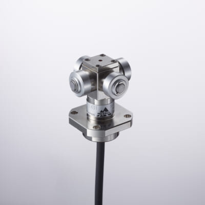
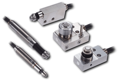
Tool Setter (Tool Length Measurement Sensor)
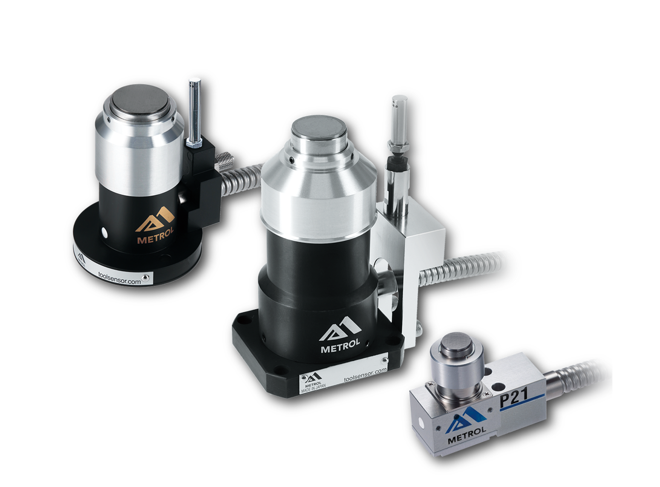
This is a contact-type sensor installed on CNC machine tools and industrial robots for tool length measurement, reference position setting, and tool breakage detection. By automatically measuring and compensating for tool length, wear, and thermal displacement inside the machine, it helps prevent machining defects and significantly reduces setup time. It is one of Metrol’s best-selling products, with a proven track record of more than 500,000 units shipped in 74 countries worldwide.
Touch Probe (On-Machine Measurement Probe)
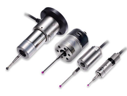
This is a contact-type probe for in-machine measurement, installed on machine tools and robots to automatically perform workpiece positioning (centering) before machining and dimensional measurement after machining. With a repeatability of 1 µm, it automates workpiece referencing and dimensional inspection, replacing skilled manual operations to reduce setup time and help prevent machining defects. Both wired and wireless models are available, meeting retrofit needs for 5-axis machining centers and robotic applications.
Air Gap Sensor (Pneumatic Sensor)
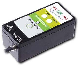
This is a non-contact sensor that uses air pressure to detect workpiece seating conditions with micron-level accuracy. It can detect gaps (“lift”) of less than 10 µm—previously difficult to measure—with a repeatability of ±0.5 µm, helping prevent machining defects and equipment downtime caused by insufficient contact between the workpiece and fixture. The sensor is used in applications such as semiconductor manufacturing processes, precision part clamping operations, and grinding wheel positioning on grinding machines, and it is a smart sensor that also supports the international standard IO-Link communication.