What Is a Contact Sensor? Types, Applications, and the Latest Trends
A contact sensor is a type of tactile sensor that detects pressure or deformation when it touches an object and outputs that information as an electrical signal. It is used in many aspects of daily life and manufacturing, such as industrial robot fingertips, smartphone touch panels, and machine-tool datum (home) setting.
While non-contact sensors detect “approach” using infrared light or magnetic fields, contact sensors achieve reliable detection by physically making contact. This enables advanced control applications such as fine force control, precise positioning, and measurement of pressure distribution.
This article explains contact sensors in an easy-to-understand way—from basic mechanisms and the characteristics of major sensing principles to practical use cases in industry, healthcare, and everyday products, as well as recent trends and notable products.
Table of Contents
What Is a Contact Sensor? An Easy-to-Understand Explanation of Mechanisms, Principles, and Structure
A contact sensor detects information obtained from physical contact and applied pressure—essentially functioning as an artificial “sense of touch.”
Just as human skin senses pressure and texture, a contact sensor converts tiny changes caused by mechanical interaction with the environment (pressing, touching, pushing against, etc.) into electrical signals.
The basic idea is to detect contact by using changes in physical quantities produced by an external force—such as resistance, capacitance, voltage, or light intensity.
A sensor must capture changes with high sensitivity while affecting the measurement target as little as possible, requiring delicacy comparable to human skin.
Although internal structures vary by sensing principle, contact sensors are generally designed to convert pressure or deformation from contact into changes in electrical characteristics.
Examples include materials whose resistance changes under pressure, electrodes whose capacitance changes with distance, crystals that generate voltage in response to strain, and optical waveguides whose light propagation changes under deformation.
Sensitivity and response characteristics differ by principle, and each has its own strengths and limitations. The following sections introduce the key characteristics of major approaches.
Comparing Major Types of Contact Sensors: Principles, Pros, and Cons
Contact sensors are based on various principles. Common approaches include resistive, capacitive, piezoresistive, and optical types. The mechanisms and pros/cons of each are summarized below.
What Is a Resistive Sensor? Mechanism and Typical Applications
A resistive sensor uses the phenomenon in which electrical resistance changes with applied pressure. It is commonly used in force-sensing resistors (FSRs) and resistive touch panels.
Two layers of flexible conductive material (such as conductive ink or polymers) are stacked. When pressed, the layers come into contact or deform, reducing electrical resistance.
As the applied force increases, the contact area and conductive paths within the material increase, raising current through the circuit. Force or pressure can be inferred from the magnitude of this change.
Advantages of Resistive Sensors: Thin, Low-Cost, and Simple Structure
Because the structure is simple and can be made thin, resistive sensors can be manufactured at low cost.
They are suitable for detecting basic contact and obtaining a rough pressure distribution. In some cases, they can be fabricated as thin-film sensors with a thickness of around 0.2 mm.
Disadvantages of Resistive Sensors: Challenges in Accuracy, Degradation, and Response
Accuracy and stability can be challenging. Sensitivity may change over time and with repeated use (for example, due to ink degradation), and calibration (break-in) may be required when starting use.
They may also require a certain minimum force to produce a detectable change, making them less suitable for measuring very small pressures or constant loads over long periods.
What Is a Capacitive Sensor? Mechanism, Structure, and Applications

A capacitive sensor is based on the principle of a capacitor. It measures changes in capacitance between two opposing conductor plates (electrodes) caused by changes in distance due to pressing, or by changes in the dielectric properties of an elastic layer between them.
A small gap or elastic layer is placed between the electrodes, and capacitance changes as its thickness changes under pressure. Sensors can also be arranged in a matrix, where each intersection of crossing electrodes functions as an individual capacitor (i.e., a “pixel”), enabling pressure to be read at each position.
Advantages of Capacitive Sensors: High Sensitivity, High Resolution, and Low Power
This approach can detect very small touches with extremely high sensitivity. Because structural deformation is small, stable performance can be maintained over long periods.
With low power consumption and easy scalability to large-area, high-density sensor arrays, it is well suited to measuring detailed pressure distributions at high resolution.
In practice, it is widely used in applications that demand high reliability and repeatability, such as smartphone touch panels.
Disadvantages of Capacitive Sensors: Noise Susceptibility and Cost
The sensor and surrounding circuitry tend to be somewhat more complex, and performance can be affected by external noise as well as temperature and humidity changes.
Small signals can be buried by parasitic capacitance between electrodes or crosstalk (interference) among multiple sensor elements, requiring high-precision signal processing and shielding measures.
In general, manufacturing costs also tend to be higher than for resistive types.
What Is a Piezoresistive Sensor? Mechanism, Features, and Use Cases
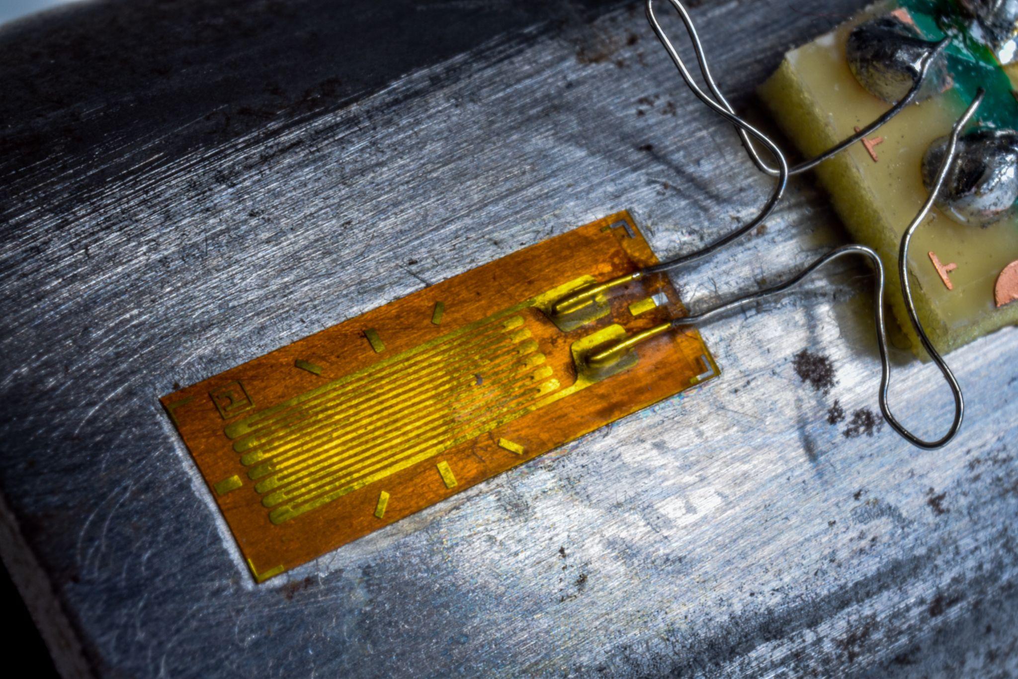
Mechanism: A piezoresistive sensor uses the piezoresistive effect—the property by which a material’s electrical resistance changes in response to applied pressure.
Typical examples include strain gauges made from semiconductors such as silicon or from metal foil. When an external force strains a component, its internal electrical resistance changes. A common structure places fine resistive elements (strain gauges) on a thin silicon diaphragm, detecting diaphragm deflection due to pressure as a change in electrical resistance.
Because mechanical strain is reflected directly in resistance, highly accurate force and pressure measurements are possible.
Advantages of Piezoresistive Sensors: High Sensitivity, Fast Response, and Low Cost
They offer high sensitivity and fast response, and signals can be read with relatively simple circuits—helping keep implementation costs low.
They are used across a wide range of products—from small MEMS devices (pressure-sensor ICs) to industrial load cells—and deliver stable performance.
Disadvantages of Piezoresistive Sensors: Effects of Temperature Drift and Hysteresis
The material and circuitry can be sensitive to temperature changes. Measurement errors may also arise due to mechanical hysteresis (a history effect in which a small residual remains even after the force is removed).
As a result, repeatability during repeated measurements and long-term stability can be challenging, and temperature compensation or unit-by-unit calibration may be required.
High Precision Positioning
- MT-Touch Switches -
0.5 μm repeatability without amplifier IP67, highly resistant to adverse environments
Click here ›Other Contact-Sensor Principles: Piezoelectric, Triboelectric, and Mechanical Approaches
In addition to the methods above, there are several other approaches to contact sensing.
What Is a Piezoelectric Sensor? How It Generates Electricity from Force and Where It’s Used
This method uses electric charge (voltage) generated when a piezoelectric element (e.g., piezoelectric ceramics or crystals) is deformed.
It responds extremely quickly to changes in external force and excels at detecting dynamic forces such as high-frequency vibration and impact. However, it is not suitable for measuring static forces (forces applied continuously at a constant level).
This is because charge is generated immediately after pressing, but if the force remains applied, the charge gradually leaks away and the voltage returns to zero.
What Is a Triboelectric Sensor? Applying the Triboelectric Effect

This method detects charge transfer caused by triboelectric electrification when different materials come into contact and separate (or rub against each other).
This technology has gained attention in recent years and is being studied as a self-powered sensor that can generate electrical signals from contact energy without an external power supply. However, because it produces a large instantaneous output voltage and is highly sensitive, it faces challenges in signal disturbance from external electrostatic noise and in overall stability.
Contact Sensing with Mechanical Switches: A Simple and Reliable Detection Method
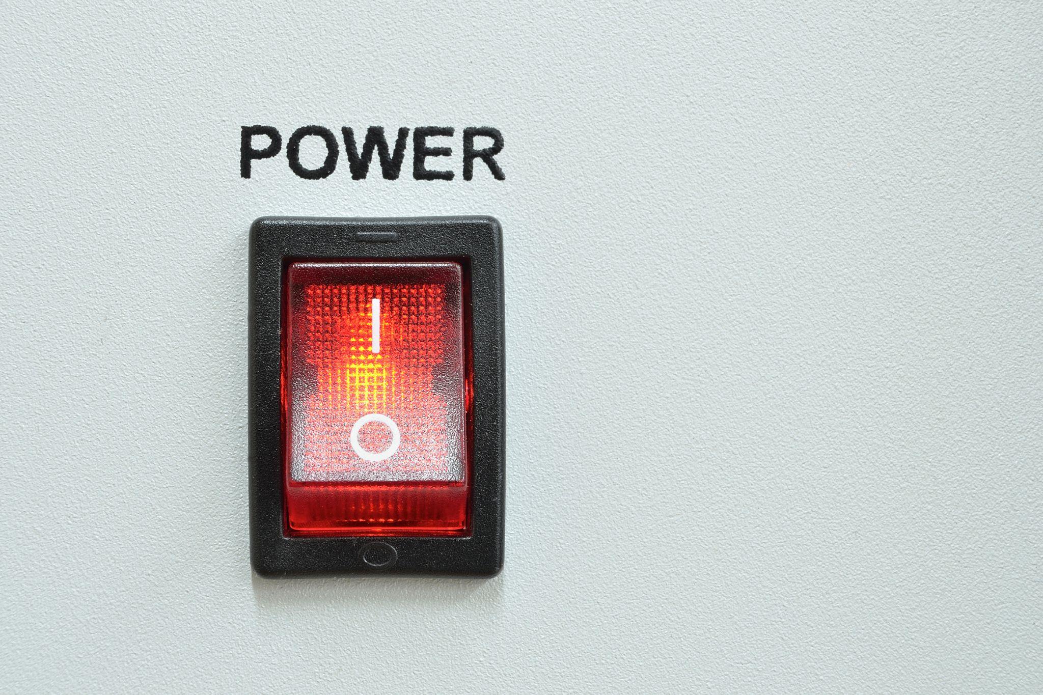
As the simplest form of contact sensor, a physical switch remains an essential option.
Limit switches and pressure switches, which toggle ON/OFF when pressed, are widely used—from industrial machinery to consumer appliances.
While the structure is simple and highly reliable, challenges remain—such as contact wear and signal noise caused by chattering (contact bounce).
High Precision Positioning
- MT-Touch Switches -
0.5 μm repeatability without amplifier IP67, highly resistant to adverse environments
Click here ›Contact Sensors Used in Machining and Design Work
Contact sensors are commonly used in machines and equipment on factory floors, but they can also be found in unexpected places—such as design environments.
Below are examples of where contact sensors are used, along with practical cautions based on on-site experience.
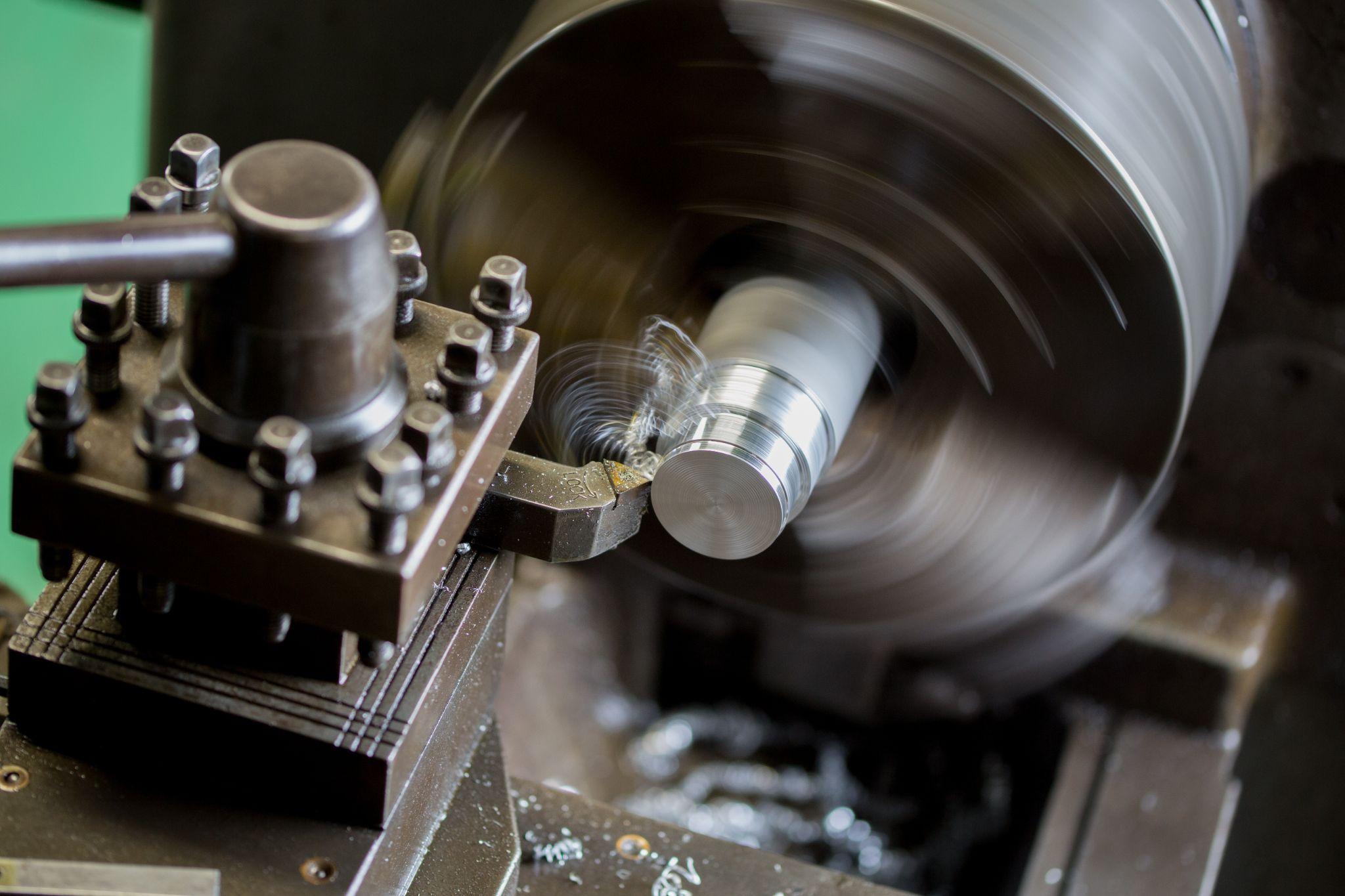
Contact Sensors Used on General-Purpose Lathes and Milling Machines
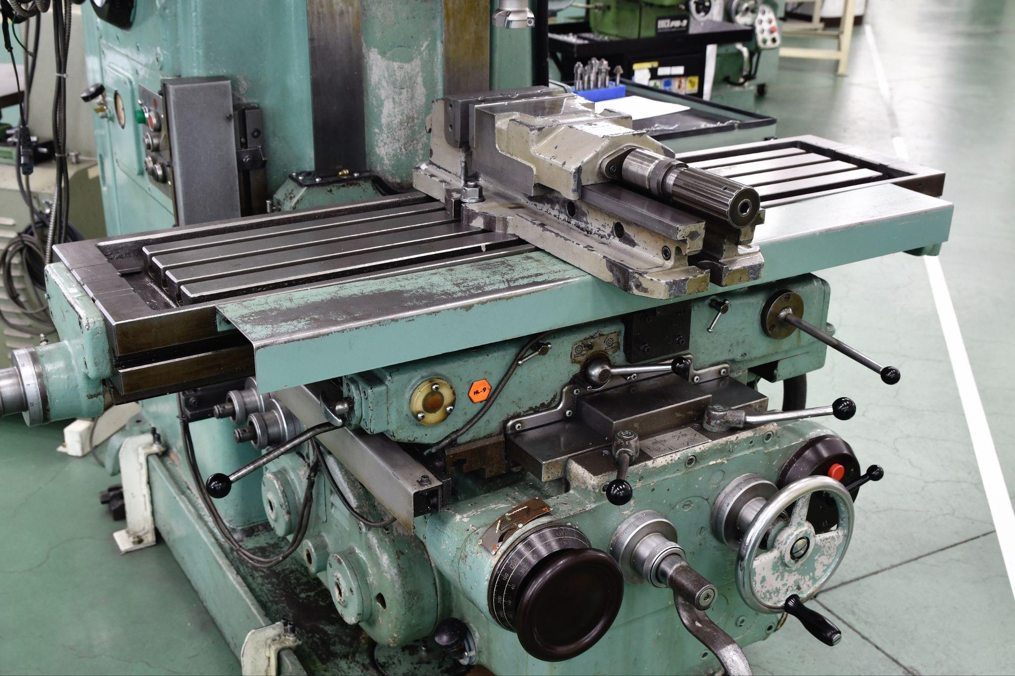
General-purpose lathes and milling machines often use mechanical limit switches (contact sensors) to restrict the machine’s travel range during operation. On lathes, these switches are located near the spindle; on milling machines, they are typically installed at both ends of the bed.
Because these sensors are installed for safety to prevent motion beyond a certain point, you must not modify them—for example, by shifting their positions.
On lathes in particular, they are installed to prevent the tool post from interfering with the spindle. Intentionally moving them is dangerous and can lead to serious accidents or machine damage.
On milling machines as well, it may be possible to increase the machining range by shifting the part that contacts the switch—but this must never be done.
Contact Sensors Used in Design Work

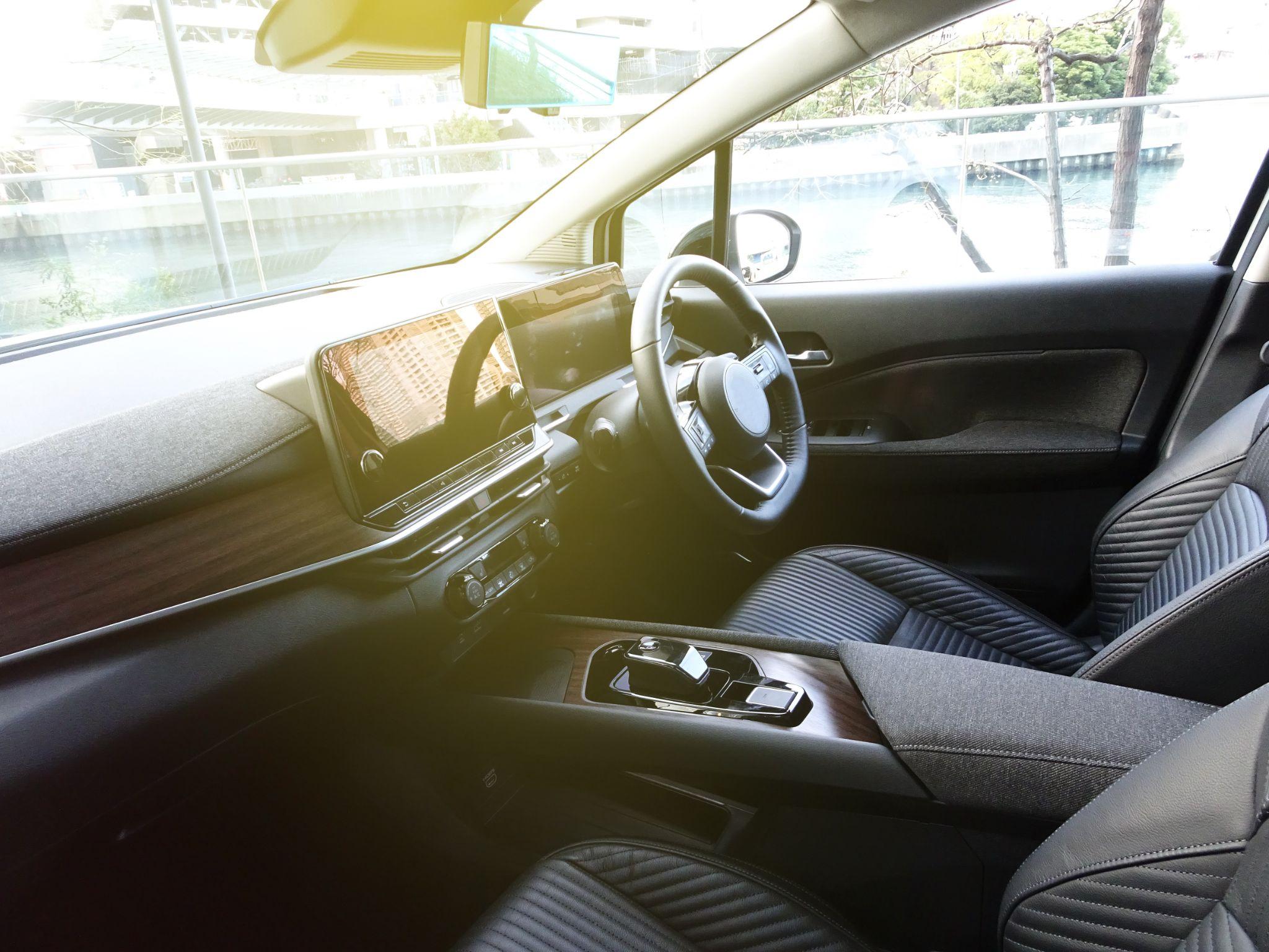
When people think of contact sensors used in design environments, many picture keypad switches for room entry/exit. But did you know contact-sensing technology is also used in CAD design work?
A notable example is the “pen display” (LCD pen tablet) that has become common for CAD drafting and design.
Pen displays are basically categorized as non-contact sensors using electromagnetic induction. However, touch-enabled models that can be operated directly with a finger use contact-sensor technology based on capacitive sensing—so they also have a “contact sensor” aspect.
Many people have experienced losing the cursor while drafting in CAD and having to move the mouse widely each time to find it again.
With a pen display, the cursor moves immediately to where you place the pen or your finger, which is very convenient. In addition, you can draw straight lines and curves without dedicated rulers, keeping your workspace uncluttered.
Contact Sensors Can Lose Accuracy Due to Contamination from the Surrounding Environment
Contact sensors installed on machines used for many years may lose accuracy due to contamination from the surrounding environment.
In environments where cutting fluid adheres or chips strike the sensor during machining, it becomes difficult to maintain the sensor’s original accuracy. This is because adhered cutting fluid and chips can harden and accelerate deterioration of mechanical parts and moving components.
Therefore, when cleaning after using a general-purpose lathe or milling machine, be sure to clean not only the sliding surfaces, bed, and surrounding areas, but also the limit-switch sections.
Contact Sensors Used for Datum (Home) Setting in Machining
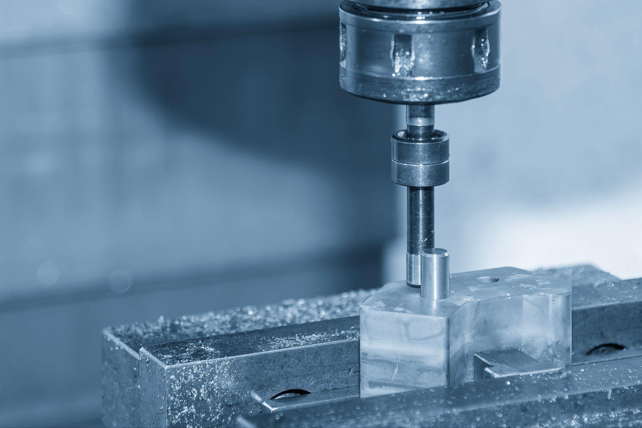
Touch sensors (edge finders) used during machining setup are also classified as contact sensors.
Some can be used only with conductive metals, while others incorporate contacts inside the touch sensor so they can measure non-conductive materials as well. However, when a workpiece is clamped using magnetic force (e.g., an electromagnetic chuck), care is required because the stylus can be influenced by magnetism.
Many touch sensors are powered by an internal battery. Before use, touch the stylus and confirm it responds via an indicator lamp (or an electronic sound). If the battery is depleted, there will be no response, increasing the risk of overtravel beyond the sensor’s allowable range and causing damage.
Although “Accu-center” tools are used less often today, they may also be considered contact sensors in the sense that they determine a datum position based on the probe’s motion (response) when it touches the workpiece.
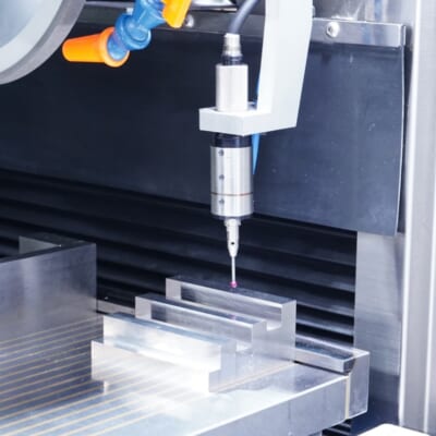
Automated workpiece centering and positioning
- Touch probe -
A contact/touch sensor for on-machine measurement that improves the efficiency of setup work
Click here ›What Are Metrol’s High-Precision Positioning Sensors?
As manufacturing automation advances and precision machining becomes more sophisticated, the number of applications requiring micron-level positioning and measurement is increasing.
Metrol’s lineup of high-precision contact sensors is designed to meet these needs.
By integrating these sensors into machine tools, industrial robots, and inspection equipment, processes such as workpiece presence detection, tool-length measurement, centering, and non-contact detection of lift-off can be achieved with high accuracy and efficiency.
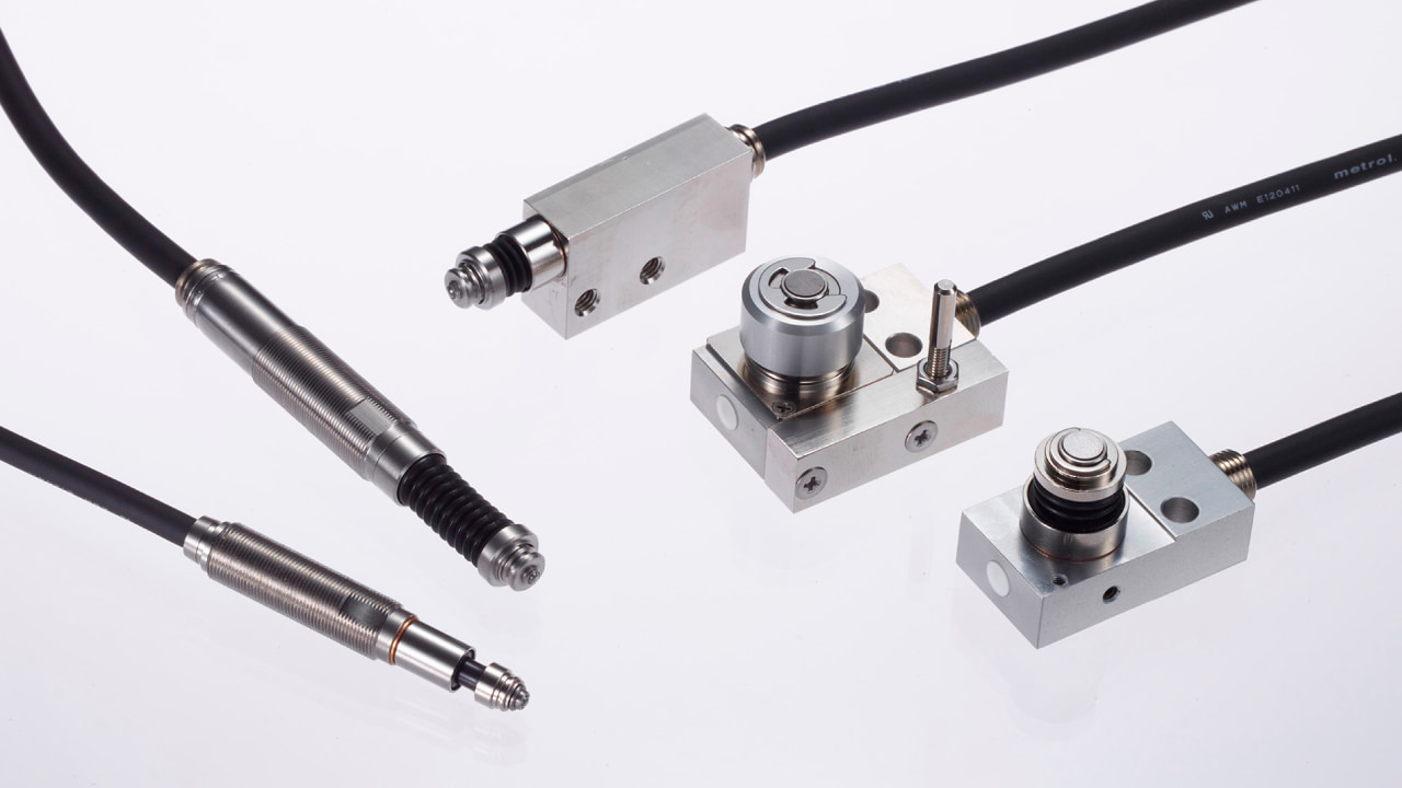
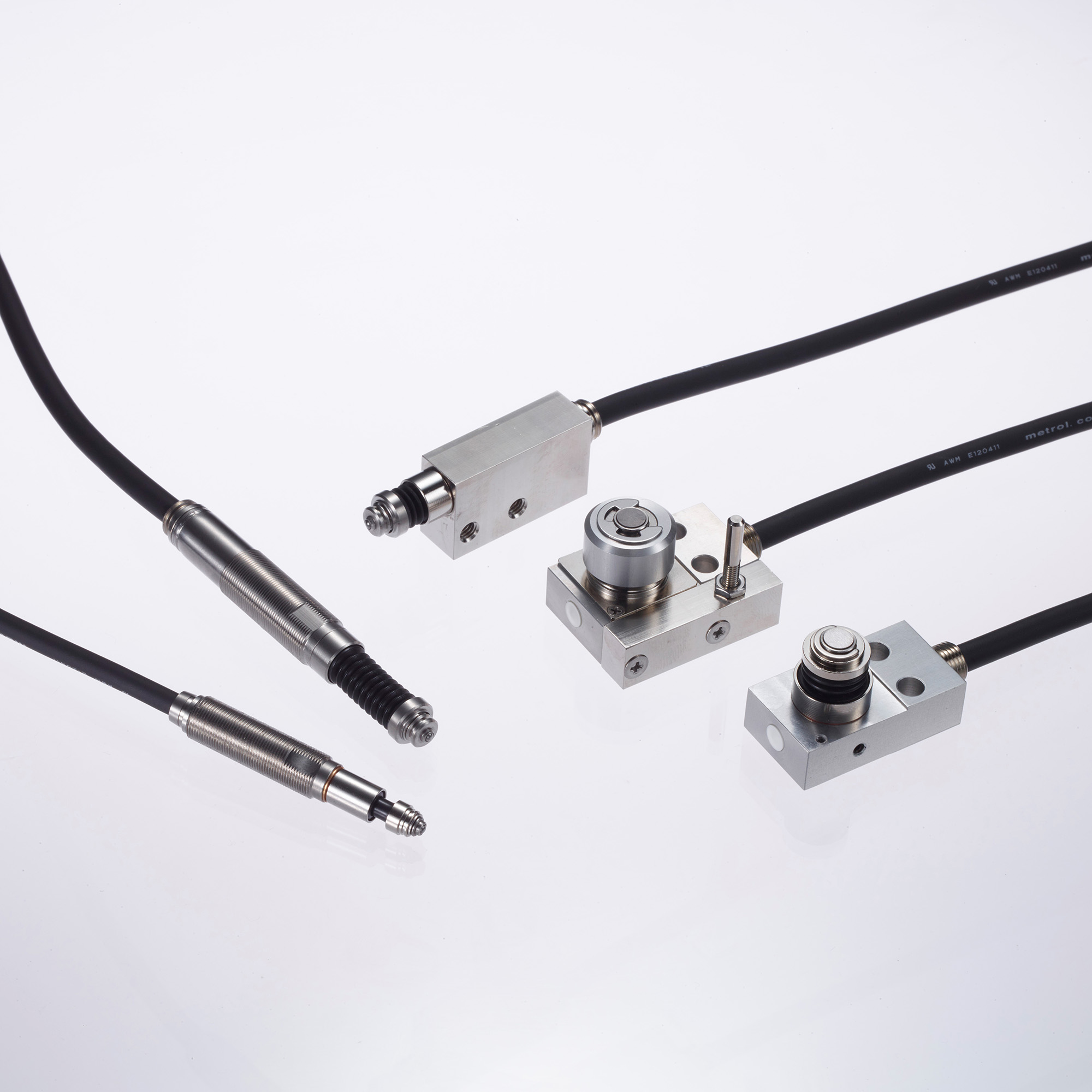
In this section, we introduce four representative positioning-sensor products developed and offered by Metrol.
All of them have extensive installation records in factories in Japan and overseas, and are used in applications that require precision control with repeatability in the 0.5 µm to 1 µm class.
High-Precision Positioning Touch Switches
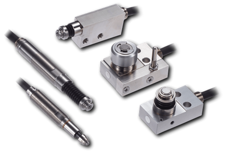
These are contact-type high-precision switches used for positioning and workpiece presence detection in machine tools, robots, and jigs. They achieve an extremely high repeatability of up to 0.5 µm and feature IP67-rated waterproof and dustproof protection, ensuring stable operation even in harsh environments. With more than 200 standard models available, they offer a wide range of variations, including designs for confined spaces, high-temperature environments, vacuum applications, and low contact force requirements.
Tool Setter (Tool Length Measurement Sensor)
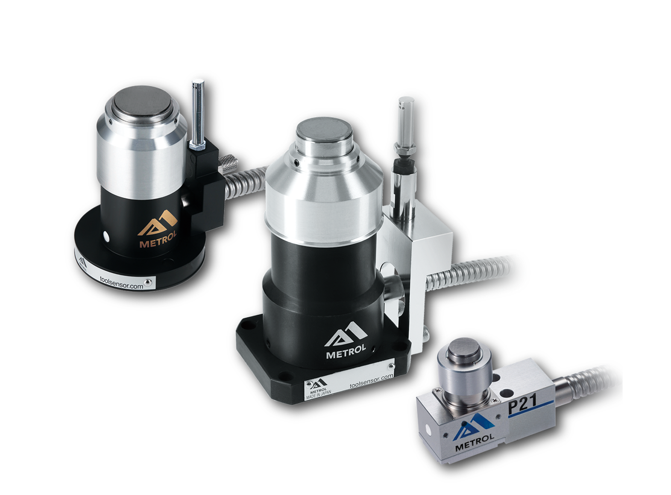
This is a contact-type sensor installed on CNC machine tools and industrial robots for tool length measurement, reference position setting, and tool breakage detection. By automatically measuring and compensating for tool length, wear, and thermal displacement inside the machine, it helps prevent machining defects and significantly reduces setup time. It is one of Metrol’s best-selling products, with a proven track record of more than 500,000 units shipped in 74 countries worldwide.
Touch Probe (On-Machine Measurement Probe)
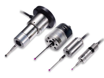
This is a contact-type probe for in-machine measurement, installed on machine tools and robots to automatically perform workpiece positioning (centering) before machining and dimensional measurement after machining. With a repeatability of 1 µm, it automates workpiece referencing and dimensional inspection, replacing skilled manual operations to reduce setup time and help prevent machining defects. Both wired and wireless models are available, meeting retrofit needs for 5-axis machining centers and robotic applications.
Air Gap Sensor (Pneumatic Sensor)
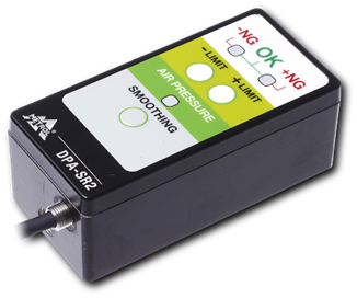
This is a non-contact sensor that uses air pressure to detect workpiece seating conditions with micron-level accuracy. It can detect gaps (“lift”) of less than 10 µm—previously difficult to measure—with a repeatability of ±0.5 µm, helping prevent machining defects and equipment downtime caused by insufficient contact between the workpiece and fixture. The sensor is used in applications such as semiconductor manufacturing processes, precision part clamping operations, and grinding wheel positioning on grinding machines, and it is a smart sensor that also supports the international standard IO-Link communication.