What Are Measuring Instruments? Types, Principles, Standards, Selection Criteria, and Practical Considerations
Measuring instruments are indispensable across virtually every field—from manufacturing sites and R&D to medical and environmental applications. Their role is to accurately quantify invisible physical quantities such as length, temperature, pressure, flow rate, and vibration, and to apply those values to quality assurance, safety management, and process improvement.
However, measuring instruments vary widely in both type and operating principle, and accurate data cannot be obtained unless they are selected and used properly.
In addition, compliance with international standards, ensuring traceability, and performing periodic calibration are also required—making measuring instruments far more important than “tools that simply measure.”
This article systematically organizes the definition and role of measuring instruments, typical types and principles, their relationship with international standards and quality management, key selection criteria, and practical considerations for design and on-site use.
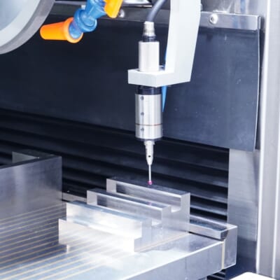
Automated workpiece centering and positioning
- Touch probe -
A contact/touch sensor for on-machine measurement that improves the efficiency of setup work
Click here ›Table of Contents
What Is a Measuring Instrument? Definition and Role
“Measuring instruments” is a general term for devices and equipment that measure and quantify a wide range of physical quantities such as length, temperature, weight, pressure, and acceleration.
In Japanese Industrial Standards (JIS), equipment that performs mechanical measurement using a motor drive is defined as a “measuring machine,” while equipment without a built-in motor is defined as a “measuring device.” In practice, “measuring instrument” is used in a broader sense that encompasses measuring machines, measuring devices, meters/indicators, standards, and more.
From manufacturing sites to R&D and medical fields, measuring instruments are essential tools for obtaining accurate data. In manufacturing, their role is to quantify the condition of products and equipment and use that information for quality control and process improvement.
For example, verifying whether a machined part’s dimensions and geometry match the drawing helps stabilize quality and prevent defective products.
By analyzing the collected data, you can also identify opportunities for improvement and optimize the production process.
Measuring instruments are not merely tools for measurement—they are fundamental to improving quality and efficiency on the shop floor.
Types of Measuring Instruments
Measuring instruments come in many forms depending on the measurement target and physical quantity. Common examples used in manufacturing can be grouped into categories such as the following.
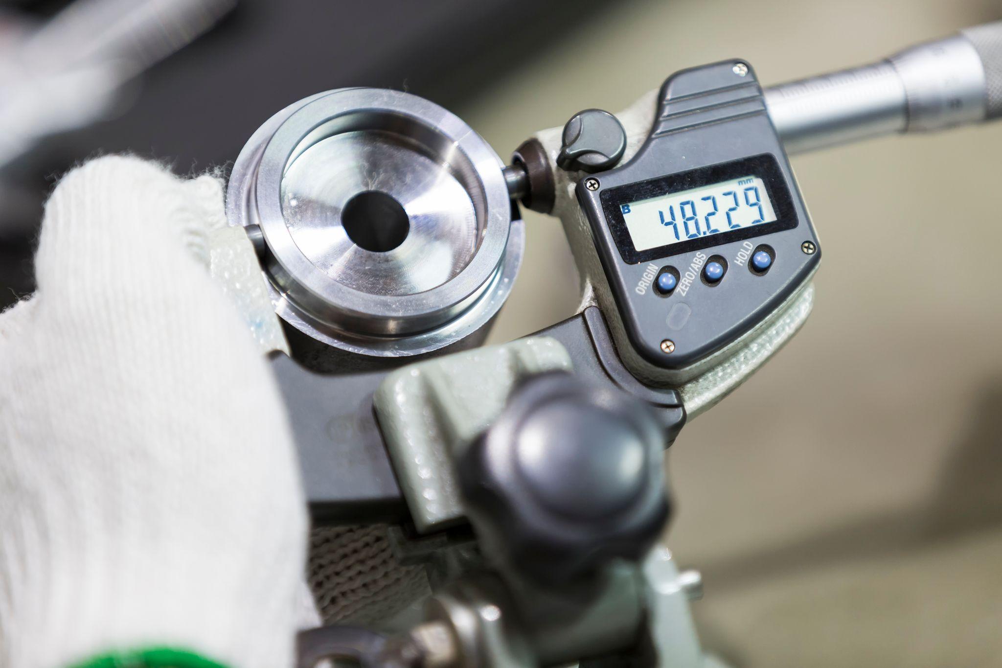
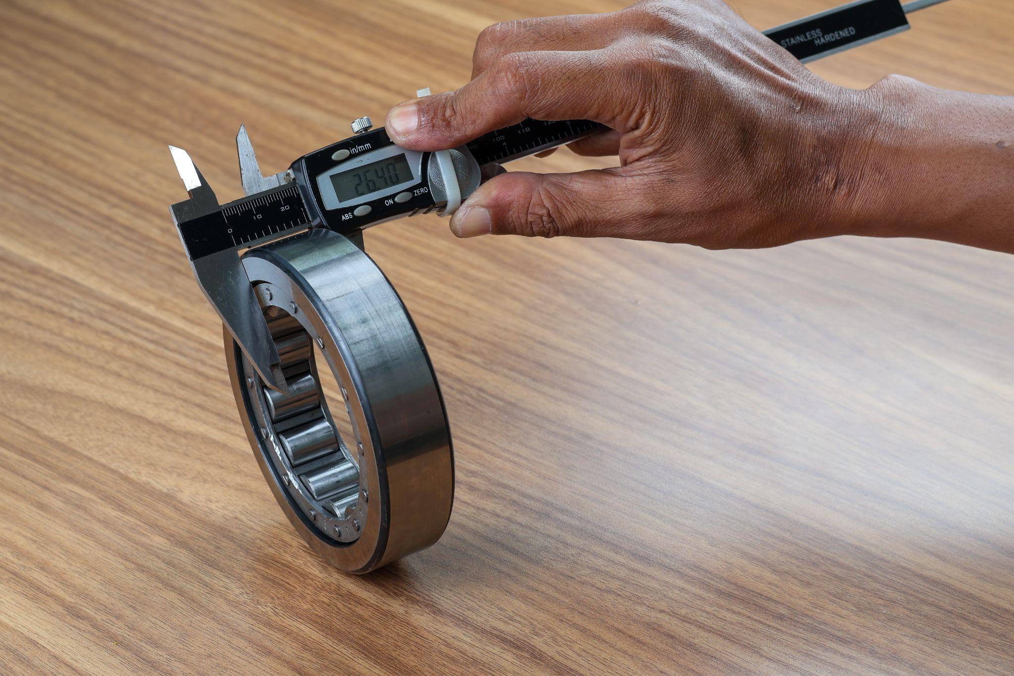
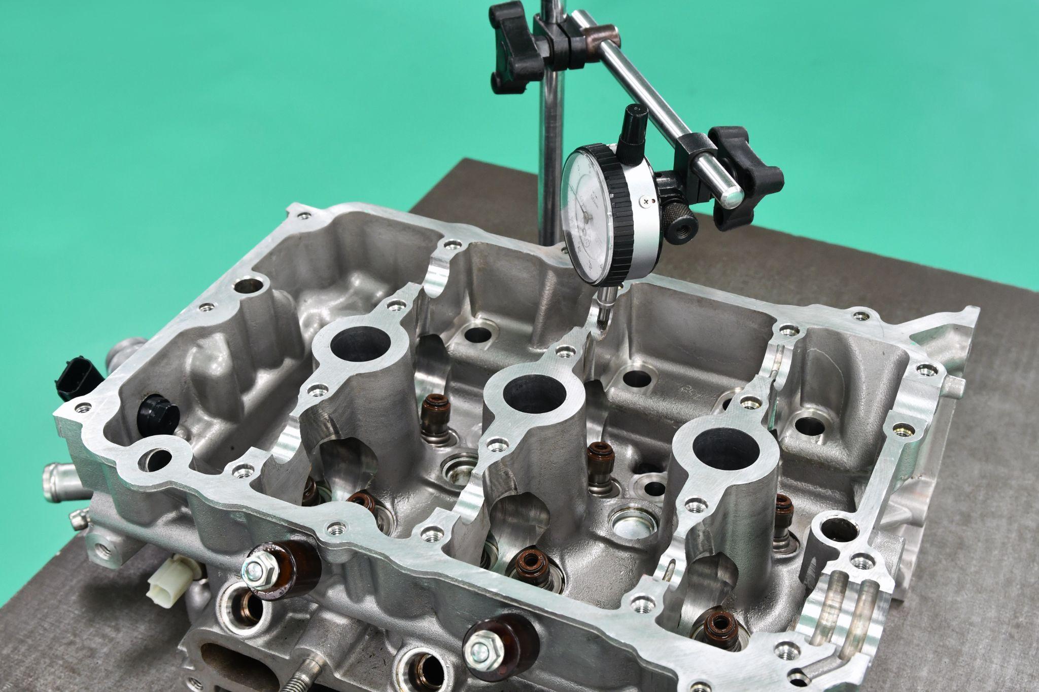
Dimensional Measuring Instruments (Length/Geometry)

Dimensional measuring instruments measure product dimensions and geometric features. Examples include calipers, micrometers, dial indicators, gauge blocks, and coordinate measuring machines (CMMs), which can precisely measure length, thickness, diameter, and more at the micron level.
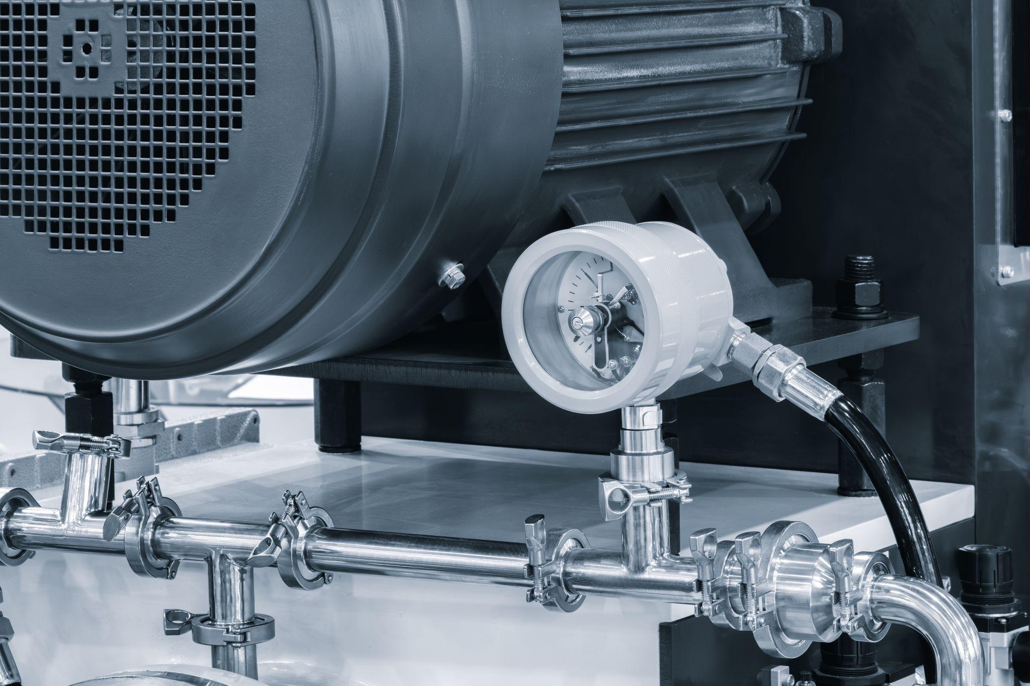
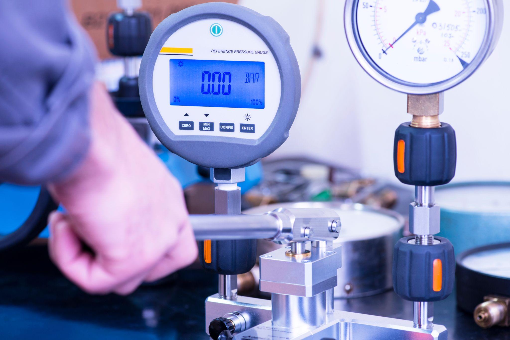
Pressure Gauges
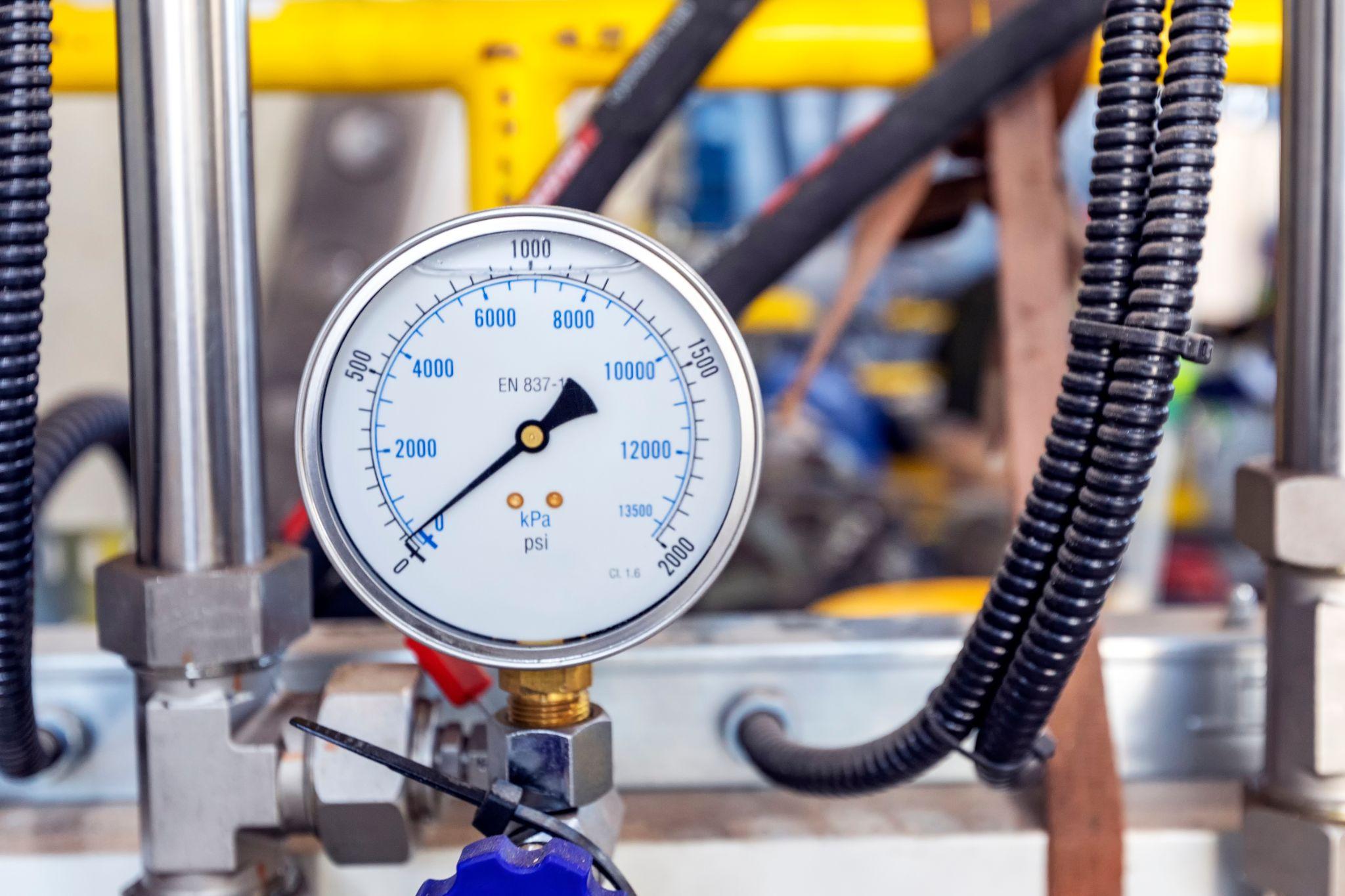
Pressure gauges are instruments for measuring the pressure of gases or liquids.
Typical analog pressure gauges indicate pressure based on the deformation of a metal tube called a Bourdon tube, while digital pressure sensors display numeric values based on changes in an electrical signal caused by pressure (e.g., strain gauges).
In factories, they are used for pressure control in piping and equipment, and for verifying safety valve settings.
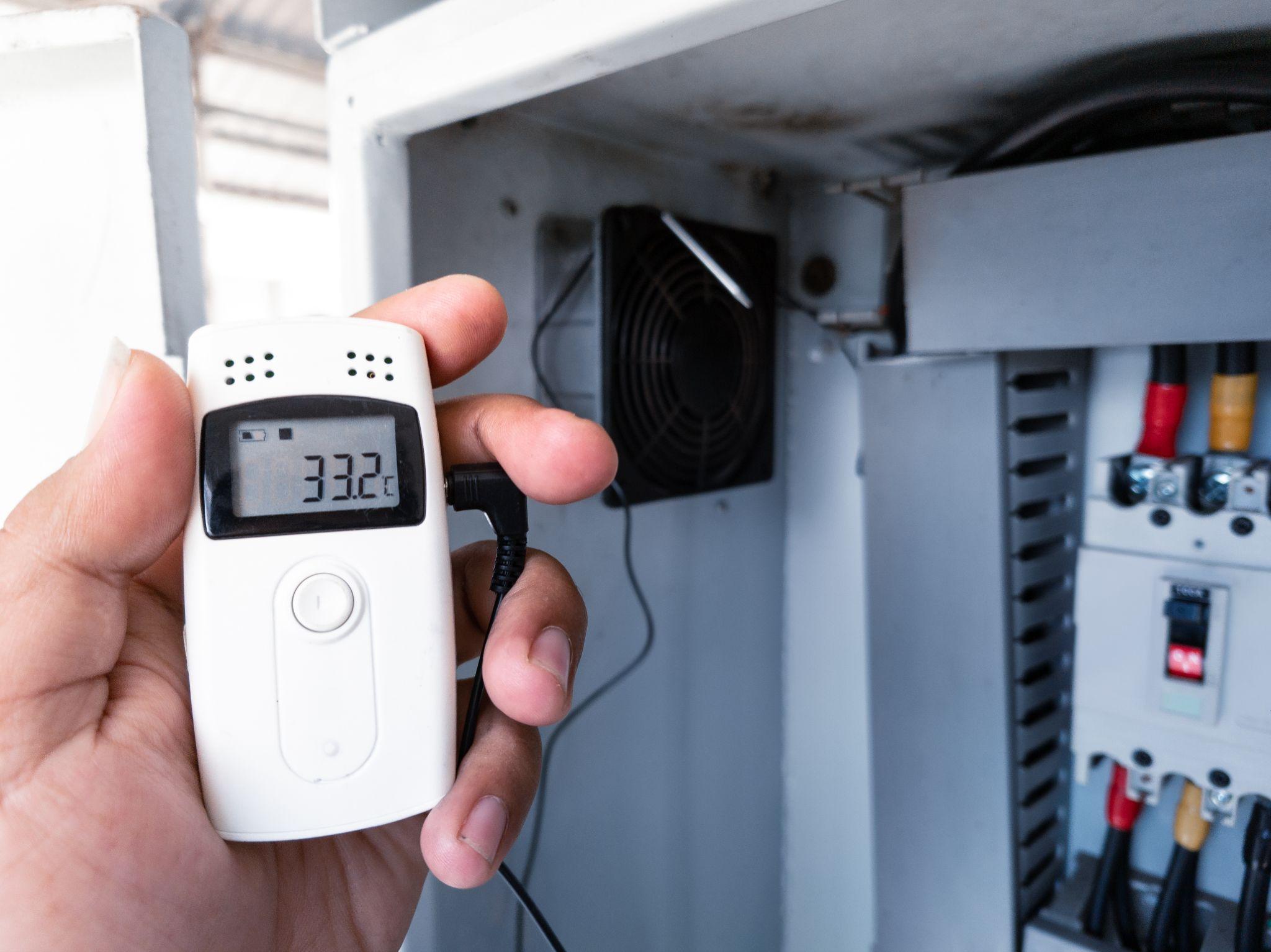
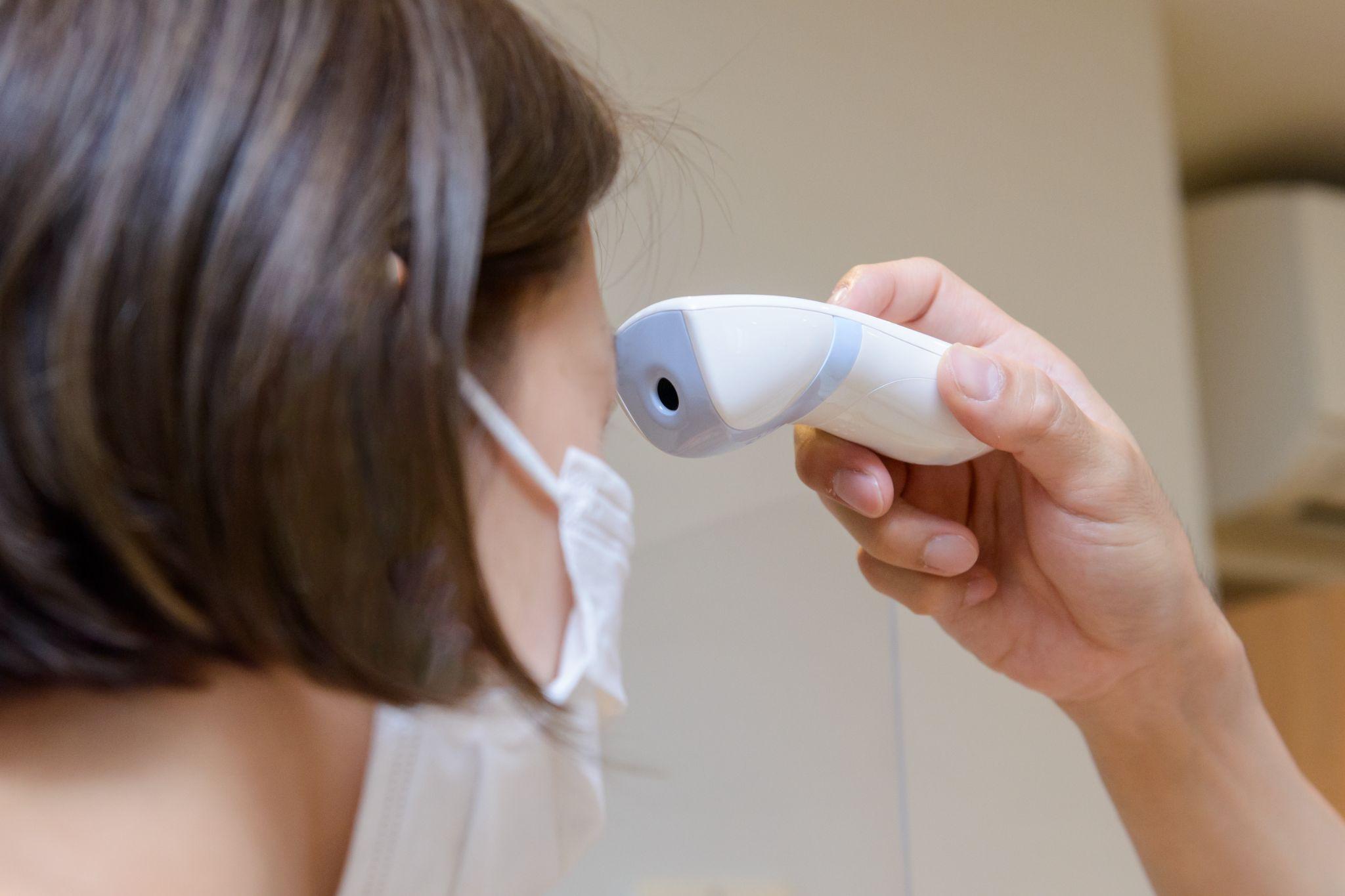
Thermometers / Temperature Instruments
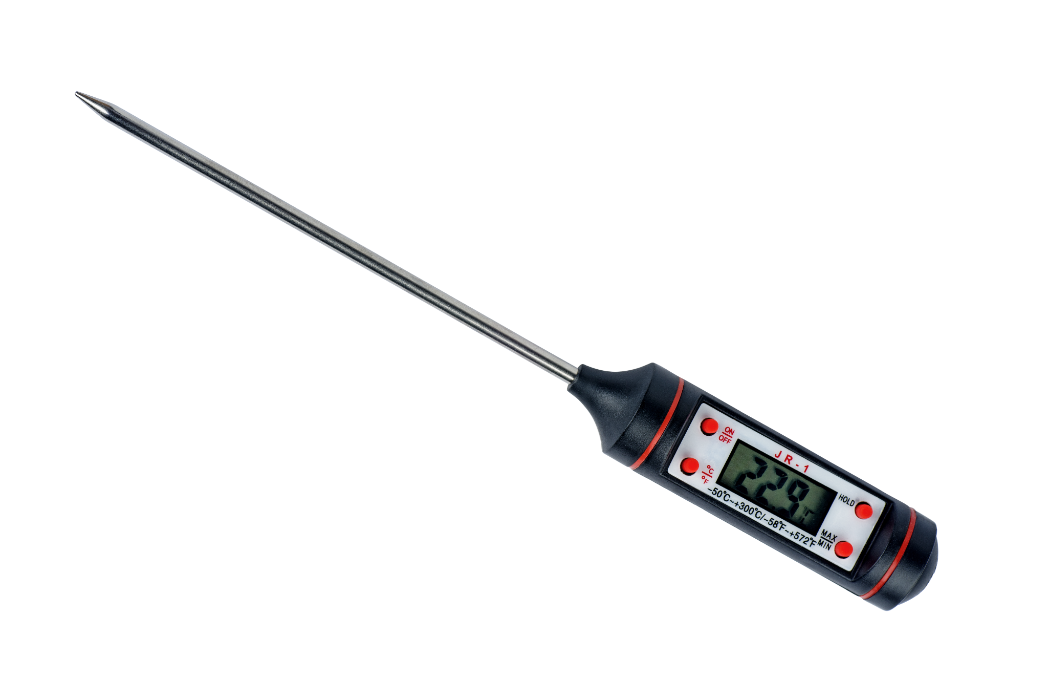
Thermometers are measuring instruments for temperature. They include mercury thermometers, bimetal thermometers, and electronic temperature instruments that use sensors such as thermocouples and resistance temperature detectors (RTDs).
Contact types measure temperature by touching the target, while non-contact types detect infrared radiation. They are essential for temperature control in manufacturing processes and for monitoring equipment overheating.
Flow Meters
Flow meters measure the flow rate of fluids (liquids and gases).
Typical examples include differential-pressure flow meters (measuring pressure drop using an orifice or Pitot tube), positive displacement flow meters, turbine flow meters, electromagnetic flow meters, and ultrasonic flow meters. They measure the volume or mass passing through piping over a given time.
They are used, for example, to manage liquid and steam flow in plant piping lines.
Vibration Meters (Accelerometers)
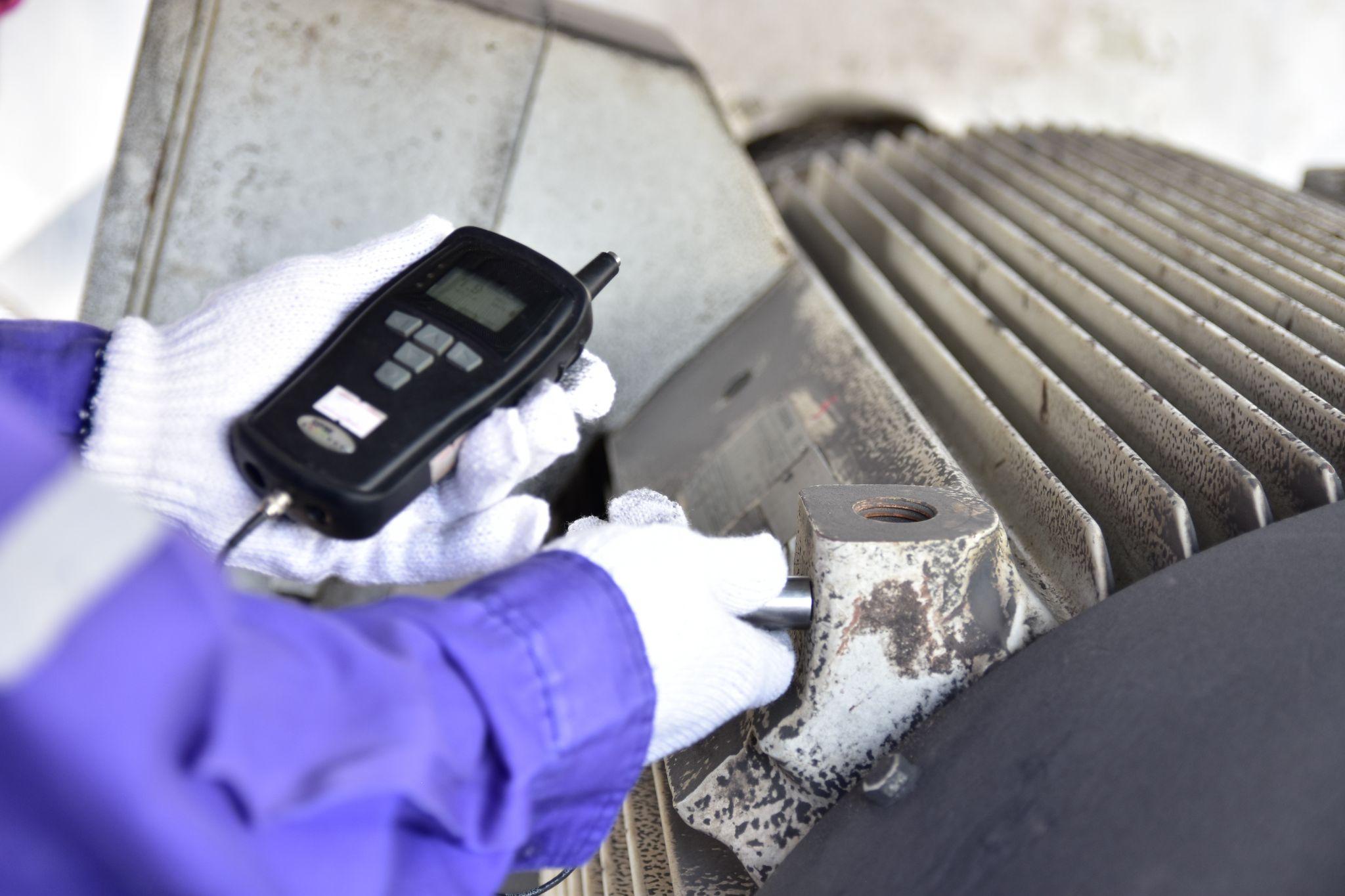
Vibration meters (accelerometers) measure the magnitude and frequency of vibrations generated by machines and structures.
They convert vibration acceleration into an electrical signal using an accelerometer (e.g., a piezoelectric element), then calculate and display metrics such as frequency, velocity, and displacement.
They are used for condition monitoring of rotating machinery (detecting abnormal vibration) and for predictive maintenance.
Sound Level Meters (Acoustic Meters)
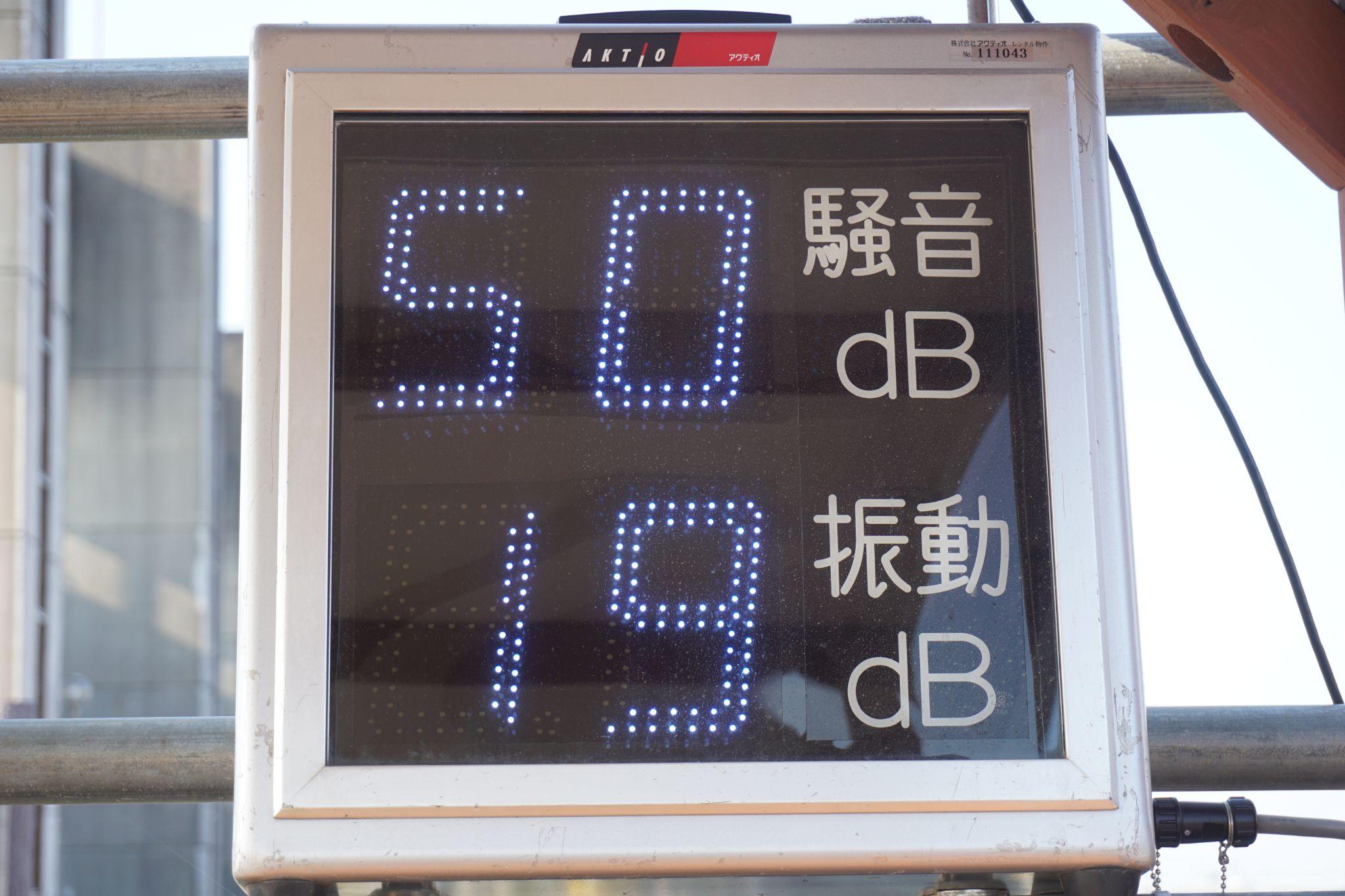
Sound level meters (acoustic meters) measure the loudness of surrounding sound (sound pressure level) in decibels (dB).
They convert sound waves into an electrical signal using a microphone, apply frequency weighting (such as A-weighting) to match human hearing characteristics, and then display the sound pressure level.
They are used to evaluate noise environments in factories and measure operating noise from machinery, helping manage working conditions and implement noise countermeasures.
High-precision seating confirmation of workpiece and jig
- Air Gap Sensor -
You can check not only "presence/absence" but also "adhesion (gap)" at the same time with a repeatability of ±0.5 μm.
Click here ›Principles and Characteristics of Measurement Methods
Measuring instruments use a variety of measurement principles, and it is important to understand their characteristics and apply them appropriately.
Common ways to classify measurement methods include “contact vs. non-contact” and “mechanical vs. electrical/electronic.”
Contact Measurement
This method measures a quantity by bringing a sensor or tool into direct contact with the measurement target.
Micrometers and calipers measure dimensions by physically clamping the workpiece, and thermocouple thermometers detect temperature at the tip of a probe in contact with the target. Contact measurement generally offers high reliability and accuracy, but it can scratch the target or introduce physical influence due to measuring force.
It can also be difficult to apply to high-speed moving objects or high-temperature targets due to risks such as damage or failure.
Non-Contact Measurement
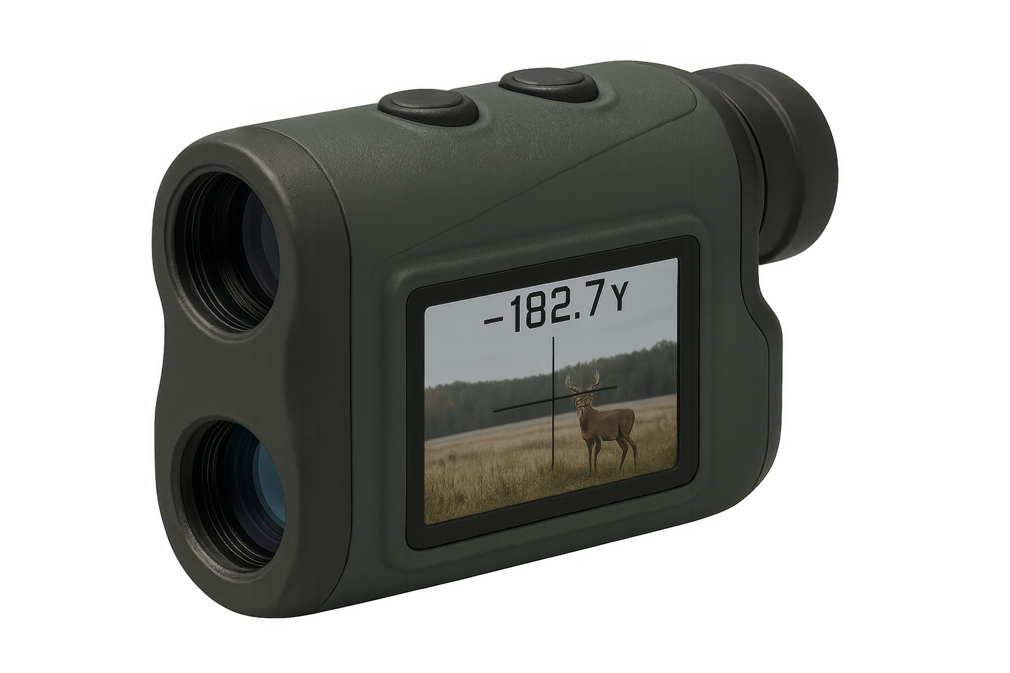
This method measures without touching the target, using laser light, ultrasound, infrared radiation, and similar technologies.
For example, optical measurement systems analyze dimensions from camera images, and laser distance meters measure distance using reflected laser light. Non-contact measurement avoids influencing the target and enables safe remote measurement.
It can measure complex shapes and soft objects, but it is more susceptible to error due to surface conditions and ambient light.
Mechanical Measurement Methods
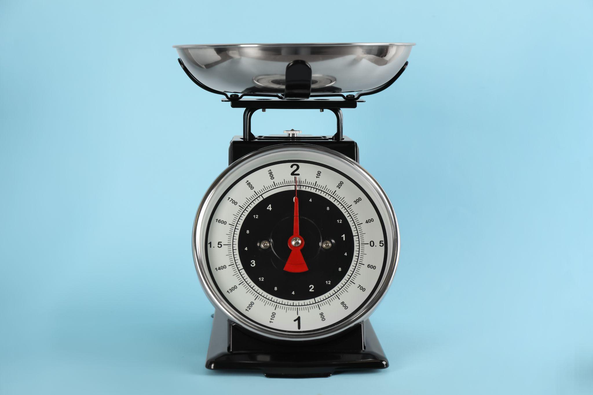
This method measures via mechanical displacement or force transmission.
It is common in analog instruments, such as force gauges using spring extension/compression and dial indicators that display amplified displacement through a lever mechanism.
Advantages include a simple structure, durability, and no need for a power supply, but readings may require skill and the measurement range can be limited.
Electrical/Electronic Measurement Methods
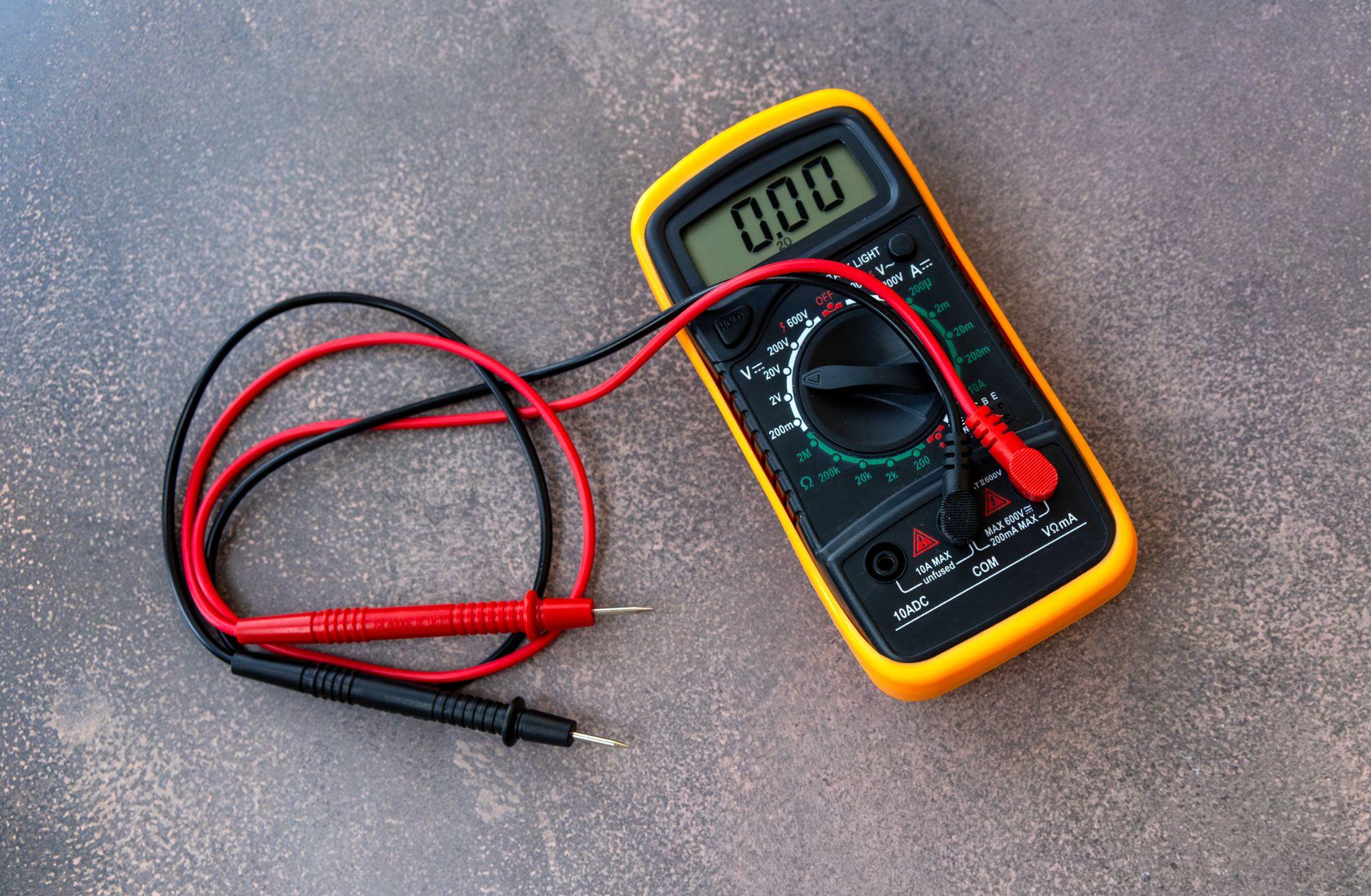
This method converts a physical quantity detected by a sensor into an electrical signal (voltage, resistance, current, etc.), then amplifies and processes it electronically to output a numeric value.
Today, many measuring instruments are electronic. For example, strain-gauge load cells convert load into a change in resistance and then calculate a numeric value electronically. Electronic methods integrate well with data logging and analysis, offer fast response, and can detect small changes. However, electrical error factors such as circuit noise and temperature drift must also be considered.
These can be combined into measurement modes such as “contact + mechanical” or “non-contact + electrical.” For example, a CMM may support both contact probes and non-contact laser probes.
It is essential to select a measuring instrument with the most appropriate principle for the target and required accuracy.
Automated workpiece centering and positioning
- Touch probe -
A contact/touch sensor for on-machine measurement that improves the efficiency of setup work
Click here ›Ensuring Accuracy, Repeatability, and Reliability (Calibration and Traceability)
Key concepts for evaluating the quality of measurement results obtained using measuring instruments include “accuracy,” “repeatability,” and “reliability.”
Accuracy indicates how close a measured value is to the true value. Repeatability indicates whether nearly the same value is obtained each time the same item is measured. Reliability refers to the degree to which you can confidently trust the measurement results.
To improve and maintain these, it is necessary to manage not only the instrument itself but also the measurement process.
First, because errors occur due to use and aging, periodic calibration is required.
Calibration is a series of activities in which an instrument’s indicated values are compared with a reference standard (traceable to national standards), deviations are confirmed, and adjustments are made as needed. Calibrated instruments should be labeled to indicate their calibration status, and a management system is also required to protect performance from improper handling or storage.
If calibration reveals an error beyond allowable limits, you must review the validity of past results measured with that instrument and, if necessary, perform product reinspection and corrective actions.
In this way, calibration and management of measuring instruments are fundamental concepts for quality assurance.
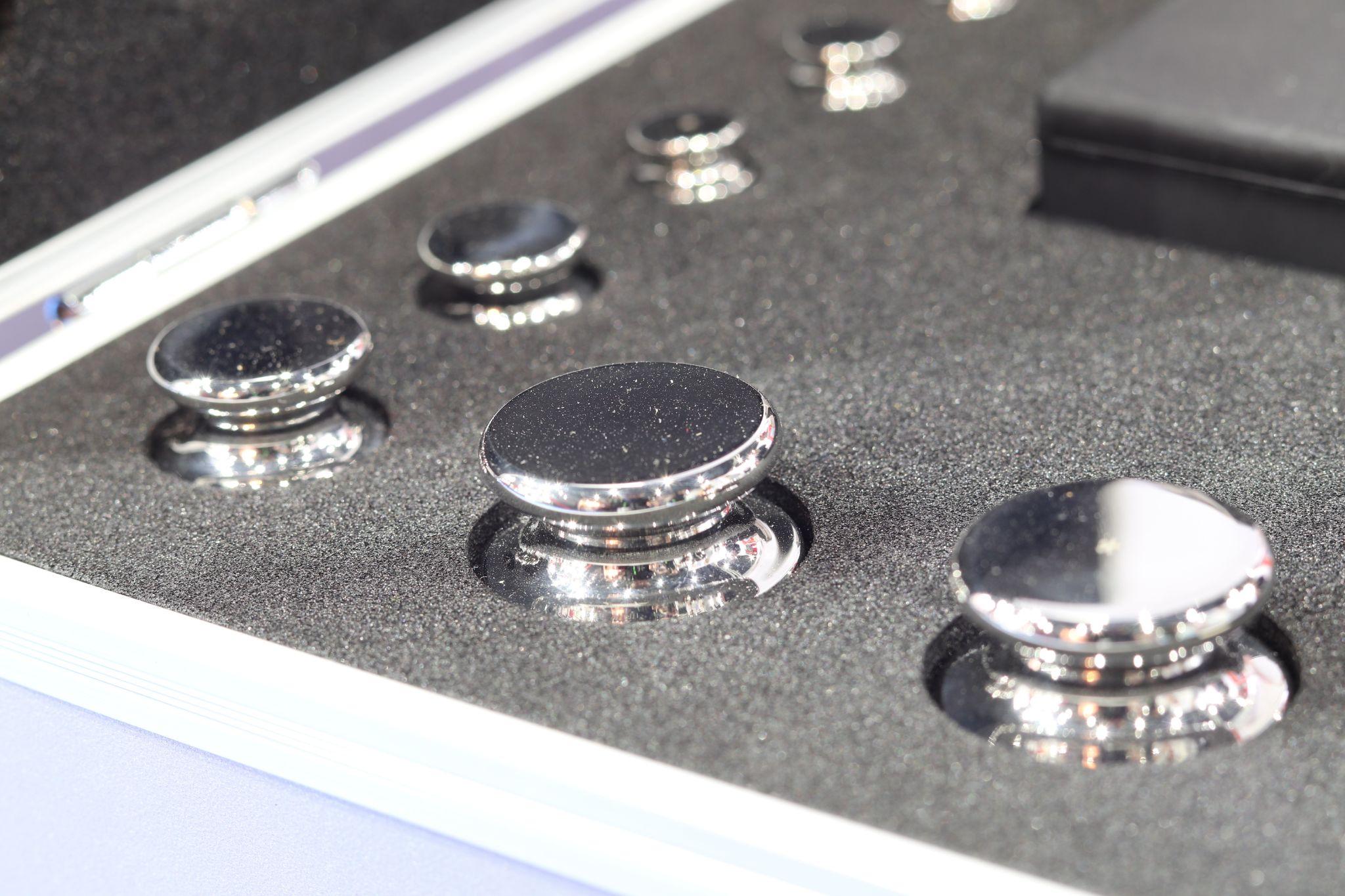
In addition, traceability (linking measurements to national standards) and measurement uncertainty (quantifying variability in measurement results) are also important concepts for objectively demonstrating reliability.
Traceability shows how well measurement values conform to national or international standards, while uncertainty evaluation clarifies how much variability (uncertainty) is associated with the result.
For example, in length measurement there is a calibration hierarchy linked to national length standards (such as gauge blocks derived from the meter standard). After ensuring traceability to that hierarchy, results may be reported with an uncertainty notation such as ±○○ μm.
This objectively assures the reliability of measurement results.
Maintaining high accuracy and repeatability also requires comprehensive measures such as user proficiency, an appropriate measurement environment (temperature/humidity control, vibration and dust management), and standardized measurement procedures.
ISO 10012 (measurement management systems), an international standard for measurement equipment management, defines a framework for ensuring measurement reliability through lifecycle management of measuring instruments, and organizations are encouraged to build accuracy management systems aligned with this framework.
Relationship Between International Standards/Quality Management and Measuring Instruments
The management and use of measuring instruments are also required by international standards from a quality management perspective. Below is a summary of representative standards and what they cover.
ISO 9001 (Quality Management Systems)
ISO 9001 is an international standard for quality assurance of products and services, and it also addresses the management of measuring instruments.
ISO 9001 requires using appropriate measurement equipment capable of producing valid results, and therefore requires calibration and management of measurement equipment.
Organizations must identify all measuring instruments in use, establish calibration plans, perform periodic calibration, and set rules such as recording and labeling calibration status.
Using measurement equipment past its calibration due date is treated as a nonconformity, and calibration due-date management is a key focus in ISO audits.
ISO/IEC 17025 (Competence of Testing and Calibration Laboratories)
ISO/IEC 17025 is an international standard for the competence of laboratories performing testing and calibration. It is not a specification for measuring instruments themselves, but it directly affects the credibility of calibration certificates.
Calibration bodies accredited to ISO/IEC 17025 meet strict requirements such as traceability to national standards, appropriate measurement procedures, and technical competence.
For example, organizations such as the Japan Quality Assurance Organization (JQA) are accredited as ISO/IEC 17025-compliant calibration providers, and their calibration certificates can be used in obtaining various certifications such as ISO 9001 and IATF 16949 (for the automotive industry).
From the user’s perspective, using ISO/IEC 17025-accredited calibration provides the advantage of demonstrating that their instrument management is internationally reliable.
Japan’s Measurement Act and Traceability
In Japan, the Measurement Act requires certain measuring instruments used for trade or certification (such as scales and weights) to undergo verification and periodic inspection.
In addition, the JCSS (Japan Calibration Service System), a calibration service accreditation scheme under the Measurement Act, has established a traceability framework in which accredited providers offer calibration services directly linked to national standards.
In corporate quality management, it is necessary to ensure instrument reliability while taking such national systems into account. Ensuring the accuracy and reliability of measuring instruments is inseparable from international standards and legal requirements.
Companies seeking certifications such as ISO 9001 typically create instrument management procedures that include centralized control via an instrument register, calibration history management, and product impact assessment when deviations occur.
Rather than treating requirements as mere compliance items, it is important to proactively use them as effective mechanisms for reducing quality risk and improving reliability in manufacturing operations.
Automated workpiece centering and positioning
- Touch probe -
A contact/touch sensor for on-machine measurement that improves the efficiency of setup work
Click here ›Key Points for Selecting Measuring Instruments
Proper selection when introducing new measuring instruments to a production site directly affects accurate and stable measurement. Below are key points to consider during selection.
Select the Type That Matches the Measurement Objective
First, clarify what you need to measure (dimensions, temperature, pressure, etc.) and select the corresponding measuring instrument.
For example, use dimensional instruments for product dimensions, and temperature instruments for equipment temperature monitoring. You also need to choose an instrument that matches the required measurement range.
Select an instrument with a suitable range and resolution for the size and magnitude of the target.
Choose a Method Suitable for the Target and Operating Environment
Depending on the target’s shape, material, and condition, evaluate whether contact or non-contact measurement is appropriate and what sensor type best fits.
For example, non-contact methods are preferable for soft materials or high-temperature objects, and ultrasonic methods can be suitable for measuring the flow of transparent liquids.
Also consider robustness for the site environment (high temperature and humidity, dust, explosion-proof requirements, etc.) and protection ratings (IP ratings).
Choose a design that matches actual use—for example, handheld units for portability, or fixed installations for continuous monitoring.
Ensure Required Accuracy and Resolution
Determine the required measurement accuracy and select an instrument that meets it. In general, higher accuracy increases cost, so it is important to choose a model with sufficient—and not excessive—performance.
For instance, using a 0.001 mm instrument where 0.1 mm is sufficient can be overkill and expensive, while an instrument that fails to meet required accuracy can lead to missed quality issues.
Also note that catalog accuracy is typically specified under ideal conditions, so evaluate instruments with on-site trials whenever possible.
If possible, try the actual unit via a trial or rental program and evaluate both accuracy and usability to reduce the risk of a poor choice.
Data Utilization and Expandability
Today, there is strong demand for importing measurement data into PCs for logging and analysis, so check whether the instrument includes digital outputs and communication interfaces (USB, Bluetooth, Ethernet, etc.).
If you plan to integrate with IoT systems in the future, consider expandability—such as whether the instrument can connect to higher-level systems or uses a modular design where only the sensor section can be replaced. Conversely, if the application is limited, too many features can make the instrument harder to use.
Evaluate the instrument holistically, including whether operators can use the interface effectively, display visibility, and maintainability.
High-precision seating confirmation of workpiece and jig
- Air Gap Sensor -
You can check not only "presence/absence" but also "adhesion (gap)" at the same time with a repeatability of ±0.5 μm.
Click here ›Practical Tips for Using Measuring Instruments in Product Design
Finally, from a product designer’s perspective in manufacturing, here are practical points on how knowledge, selection, and use of measuring instruments can help—and how to avoid common pitfalls.
Considering measurement at the design stage pays off later—especially during late-phase evaluation testing and failure analysis.
Design with Measurability in Mind
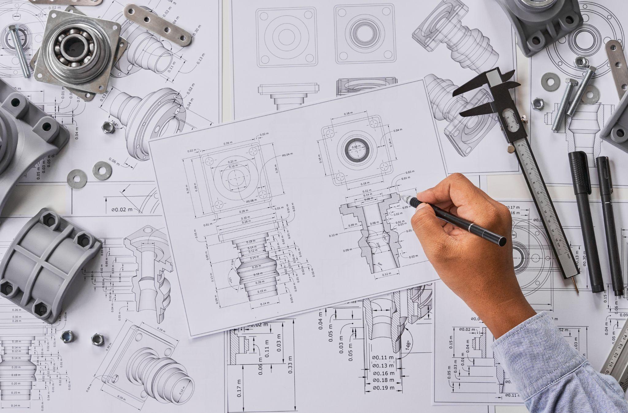
Beyond simply designing to meet drawing requirements, it is crucial at the design stage to consider whether the specifications can be properly measured and verified.
For example, if you specify tight tolerances, you must ensure the availability of inspection fixtures or a CMM capable of measuring them. If a product has complex internal structures, you may need to consider non-destructive inspection or endoscopic measurement methods.
Designers are responsible for planning verification of their designs and selecting appropriate instruments and methods. Designs that are difficult to measure cause problems not only in mass-production inspection, but also in identifying root causes when issues arise during development.
Therefore, design with the constant question in mind: “Which instrument can measure this characteristic value, and with what accuracy?”
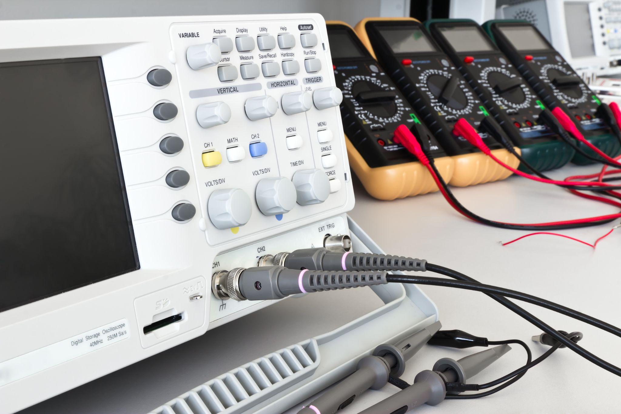
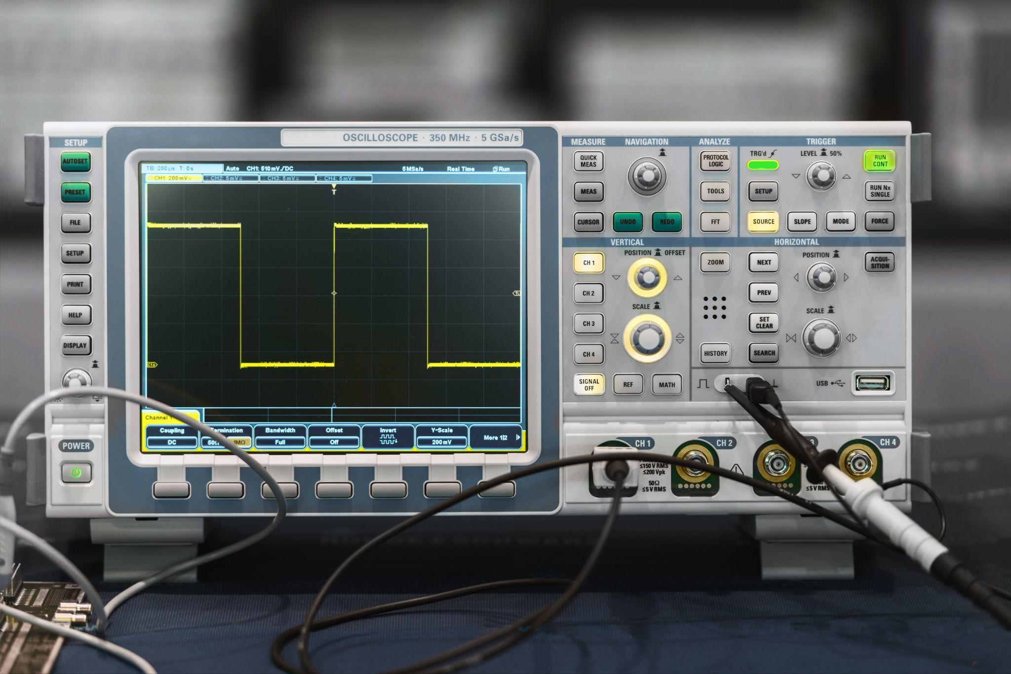
Understand Measurement Range and Performance Limits
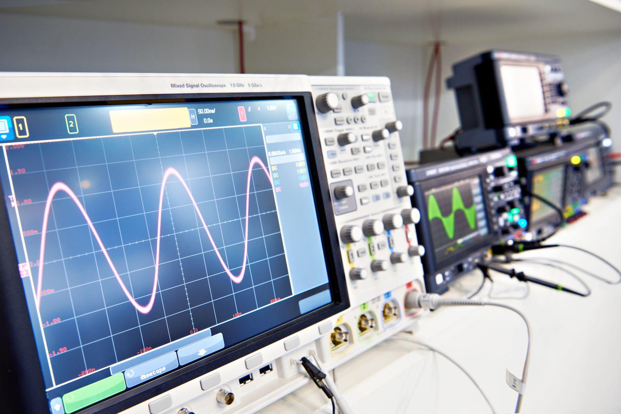
Designers often handle measuring instruments during prototype evaluation. In those situations, it is important to understand the performance limits of the instrument being used.
For example, when observing high-speed signals with an oscilloscope, confirm that bandwidth and sampling rate are sufficient. For load testing, confirm that load cell capacity and accuracy match the purpose.
Verifying in advance that the target values fall well within the instrument’s capability is fundamental. If you neglect this, data may saturate outside the measurement range or be buried in noise, leading to incorrect conclusions.
During design-stage testing, read the instrument manual to understand specifications such as measurement range, accuracy, and response. If needed, consider higher-end models or alternative measurement methods.
Measurement Uncertainty and Statistical Analysis

Designers should avoid taking measurement results at face value and develop a habit of considering uncertainty and sources of variation. Instead of judging pass/fail from a single reading, measure multiple times to assess repeatability and, if possible, cross-check with instruments based on different principles—this caution helps prevent mistakes.
Analyze the obtained data using statistical methods. Calculating confidence intervals and process capability indices provides objective support for quality decisions.
Especially in development, measurement data is often limited. Designers should proactively propose additional data collection and work to increase sample size—even by devising simple experimental setups.
Doing so enables sufficient verification against product specifications and significantly reduces the risk of unexpected issues after transitioning to mass production.
Inspect and Calibrate In-House Dedicated Gauges Periodically, Just Like Measuring Devices
Not everyone involved in machining on the shop floor can check product dimensions with the same skill level as experienced craftsmen.
On production lines, dedicated gauges with specialized shapes are sometimes used so that less-experienced operators or part-time staff can easily verify dimensions.
Such in-house dedicated gauges also require periodic dimensional inspection and calibration.
Even if a gauge is hardened (e.g., by heat treatment), frequent shop-floor use inevitably causes deformation and wear. Dimensions can also change with ambient temperature, so stable checks throughout the year are not guaranteed.
For sites using in-house dedicated gauges, periodically verify the dimensions of the “shop-floor gauge,” and prepare a separate “inspection gauge” stored in a temperature-controlled environment such as an inspection room.
This way, even if the shop-floor gauge has drifted, the inspection gauge provides a reference, helping prevent the outflow of defective products even in the event of a large-scale occurrence on the shop floor.
What Are Metrol’s High-Precision Positioning Sensors?
The foundation of machining accuracy is reliably confirming whether the workpiece and tool are positioned correctly.
Even a misalignment of just a few µm can lead to defects or tool damage, so positioning sensor performance directly affects productivity and quality.
Metrol offers a wide lineup of high-precision sensors, including touch switches with 0.5 µm repeatability and air micrometer sensors capable of detecting gaps below 10 µm.
Here, we introduce Metrol’s representative sensor products and their features that directly address on-site challenges.
High-Precision Positioning Touch Switches
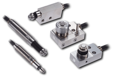
These are contact-type high-precision switches used for positioning and workpiece presence detection in machine tools, robots, and jigs. They achieve an extremely high repeatability of up to 0.5 µm and feature IP67-rated waterproof and dustproof protection, ensuring stable operation even in harsh environments. With more than 200 standard models available, they offer a wide range of variations, including designs for confined spaces, high-temperature environments, vacuum applications, and low contact force requirements.
Tool Setter (Tool Length Measurement Sensor)
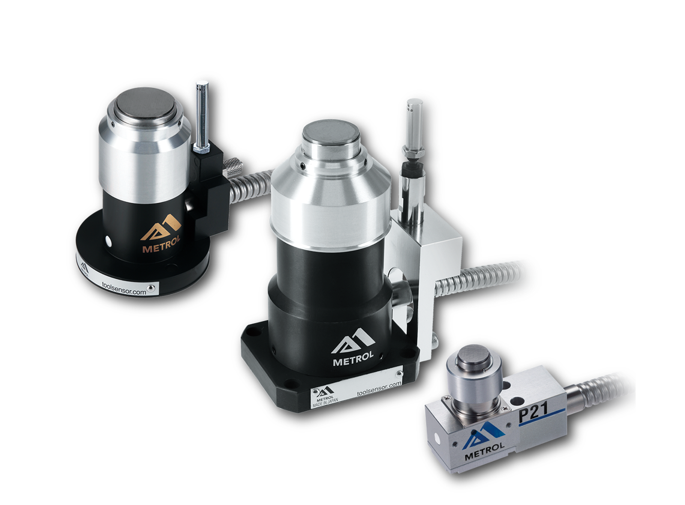
This is a contact-type sensor installed on CNC machine tools and industrial robots for tool length measurement, reference position setting, and tool breakage detection. By automatically measuring and compensating for tool length, wear, and thermal displacement inside the machine, it helps prevent machining defects and significantly reduces setup time. It is one of Metrol’s best-selling products, with a proven track record of more than 500,000 units shipped in 74 countries worldwide.
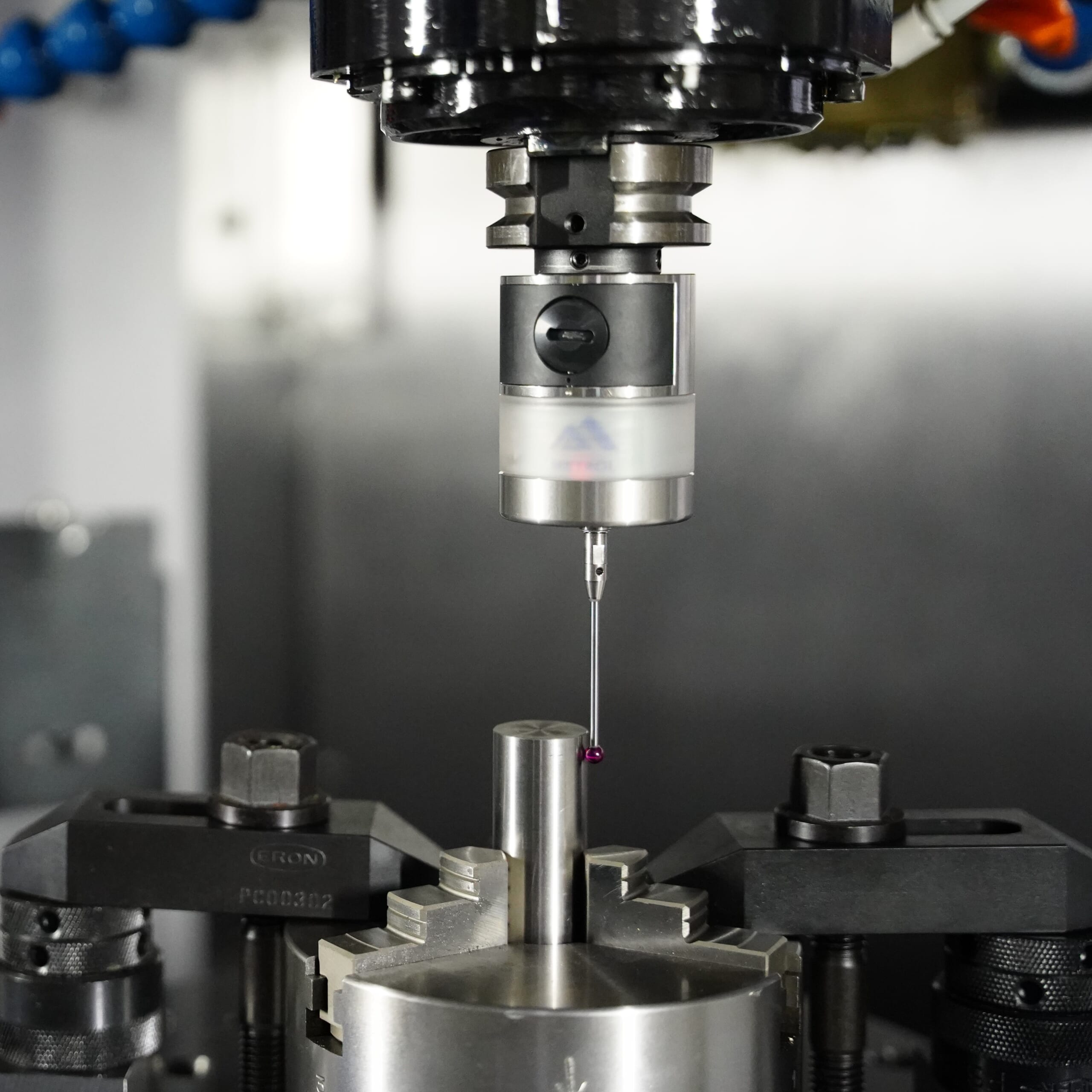
Touch Probe (On-Machine Measurement Probe)
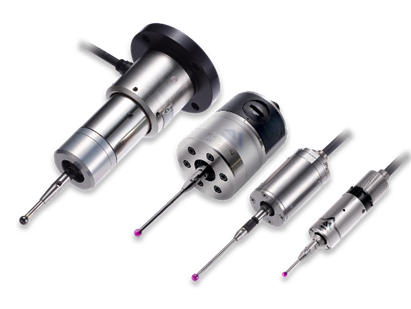
This is a contact-type probe for in-machine measurement, installed on machine tools and robots to automatically perform workpiece positioning (centering) before machining and dimensional measurement after machining. With a repeatability of 1 µm, it automates workpiece referencing and dimensional inspection, replacing skilled manual operations to reduce setup time and help prevent machining defects. Both wired and wireless models are available, meeting retrofit needs for 5-axis machining centers and robotic applications.
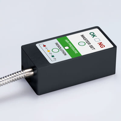
Air Gap Sensor (Pneumatic Sensor)
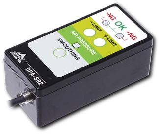
This is a non-contact sensor that uses air pressure to detect workpiece seating conditions with micron-level accuracy. It can detect gaps (“lift”) of less than 10 µm—previously difficult to measure—with a repeatability of ±0.5 µm, helping prevent machining defects and equipment downtime caused by insufficient contact between the workpiece and fixture. The sensor is used in applications such as semiconductor manufacturing processes, precision part clamping operations, and grinding wheel positioning on grinding machines, and it is a smart sensor that also supports the international standard IO-Link communication.