What Are Chips (Swarf)? A Clear Guide to How They Form, How to Handle Them, and Practical Shop-Floor Insights
“Chips” are inevitable in metalworking and machining operations.
They may look like mere waste, but they directly affect machining accuracy, workplace safety, machine life, and even environmental impact—making them an essential factor in manufacturing.
Understanding chip shapes and formation mechanisms helps you choose the right tools and set cutting conditions properly, which in turn reduces defects and lowers costs.
This article systematically explains chip types, how chips form, handling methods, recycling technologies, on-site management examples, and key design considerations engineers should understand.
High-precision seating confirmation of workpiece and jig
- Air Gap Sensor -
You can check not only "presence/absence" but also "adhesion (gap)" at the same time with a repeatability of ±0.5 μm.
Click here ›Table of Contents
What Are Chips (Swarf) in Machining?
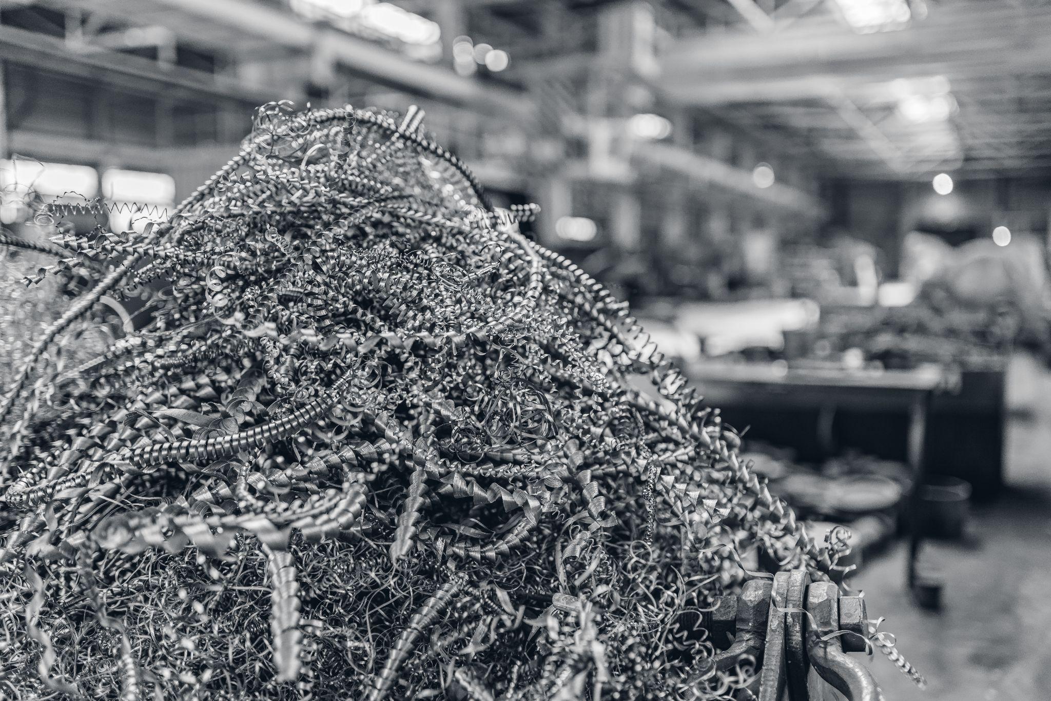
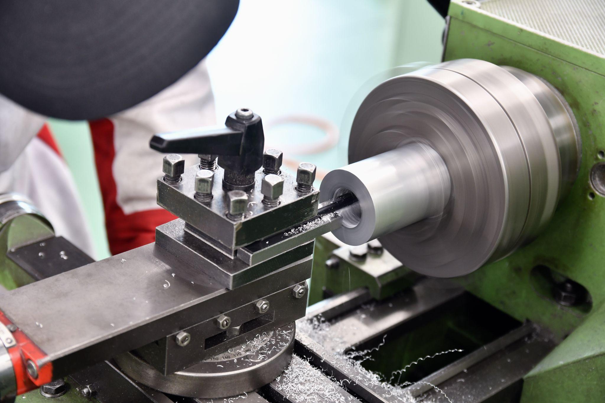
“Chips” refer to small pieces or powder-like residues removed from a workpiece during material removal processes such as cutting and grinding using machine tools.
Turning often produces long, stringy chips, while milling tends to generate more granular or powdery chips. In a broader sense, sawdust from woodworking and dust from polishing can also be considered “chips.”
Chips are an unavoidable byproduct of material removal, but how you handle them can significantly impact safety, productivity, and environmental load.
Proper chip management is crucial for maintaining a safe shop floor, improving efficiency, and protecting the environment.
Chip Types and Classification
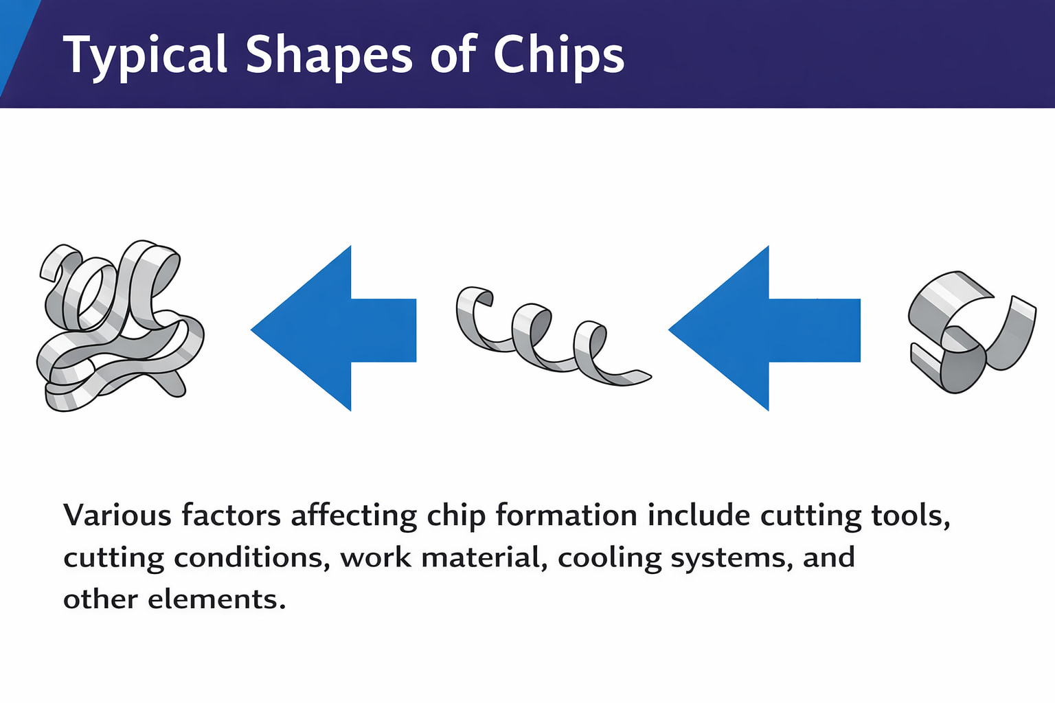
Chips appear in many shapes and conditions, and different types form depending on cutting conditions and material properties.
The main chip forms are as follows.
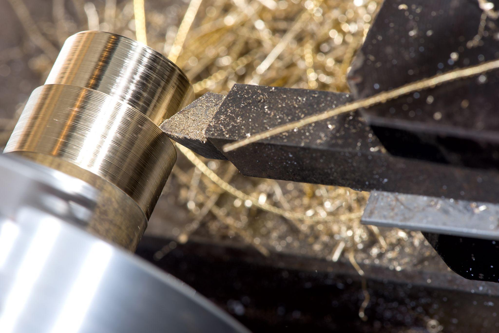
Continuous Chips (Long Chips)
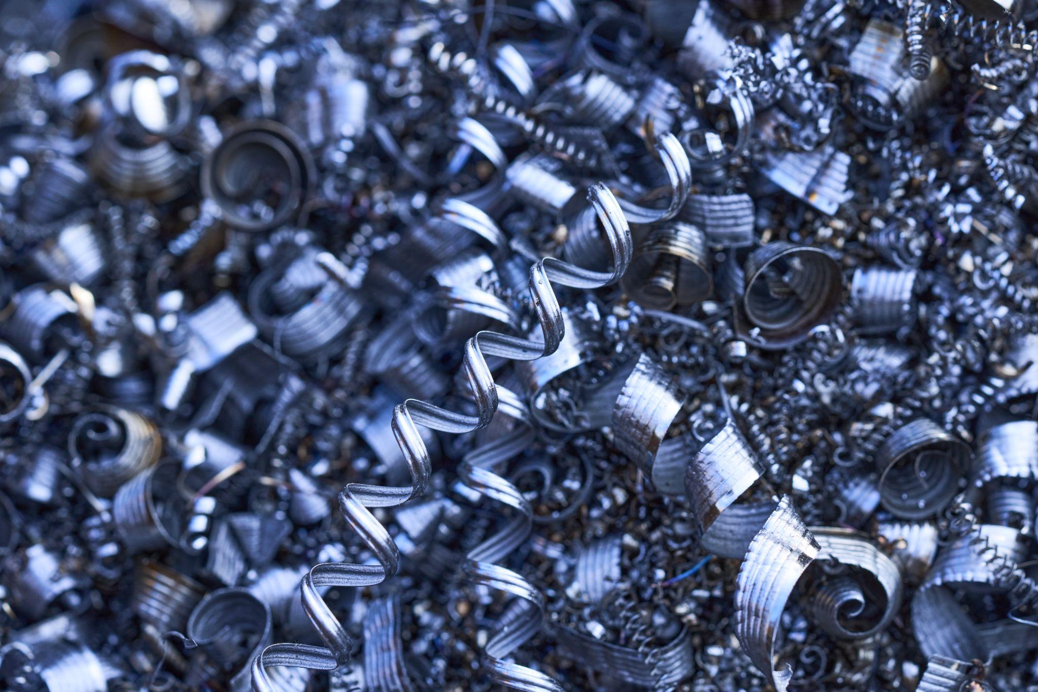
These are chips connected into a long strip or coil.
They are likely to form when cutting soft, ductile metals at high speed, and can offer benefits such as good surface finish and longer tool life.
However, because they are long and easily entangle, evacuation and post-processing become difficult. Inside the machine, chips can swirl and tangle into “bird’s nest” formations, causing trouble.
Long chips can also wrap around and injure operators, so countermeasures are typically required—such as using a chip breaker (a tool geometry designed to break chips) to control chip length.
Discontinuous Chips (Short Chips)
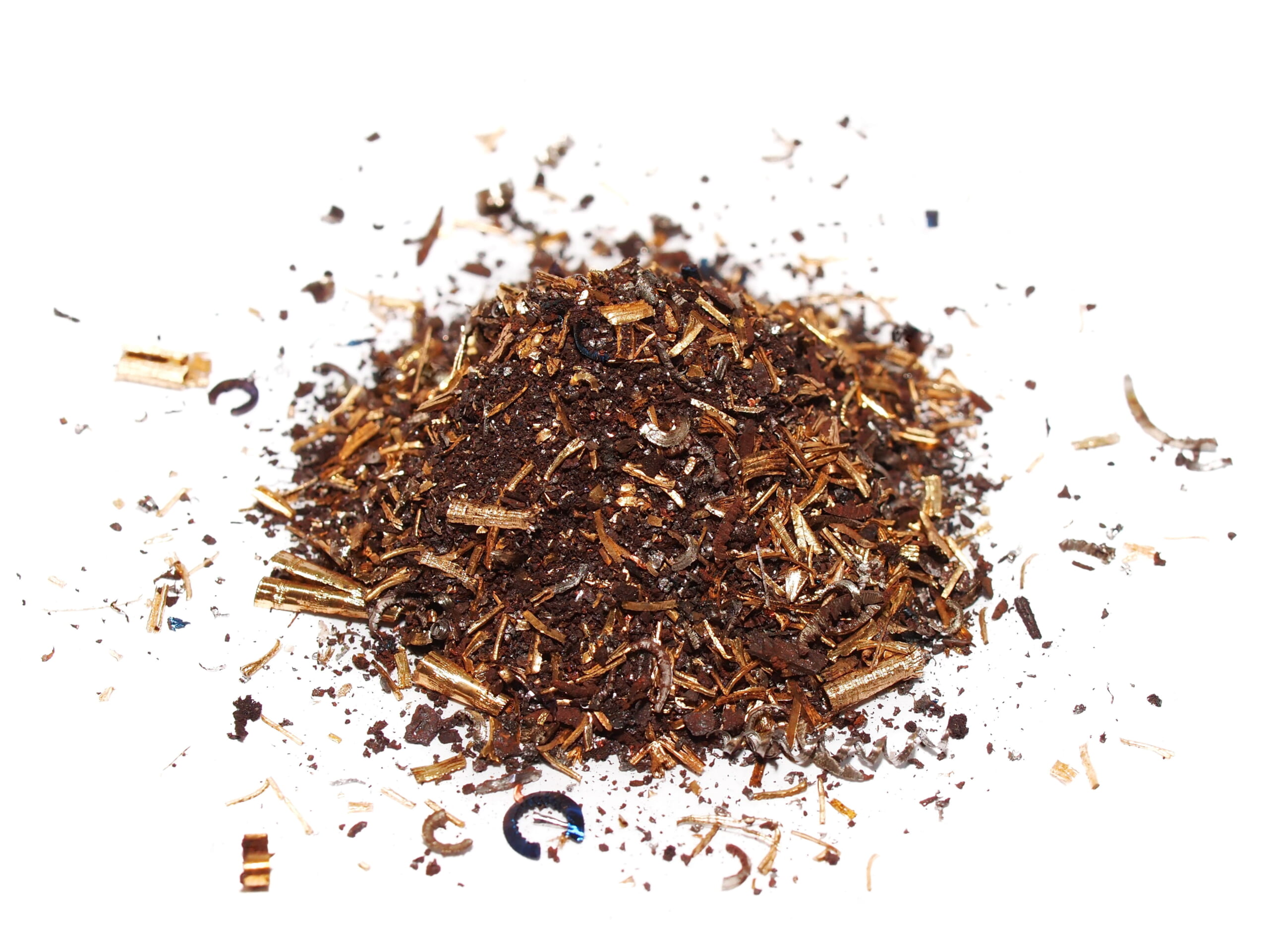
These are short, fragment-like chips that break intermittently.
They tend to occur when machining hard, brittle materials (e.g., cast iron, brass) or under conditions of low cutting speed and high feed, where chips break into small pieces.
Discontinuous chips are less likely to tangle and are easier to handle, but forcing discontinuous chip formation in ductile materials can worsen surface finish and increase machining time.
Serrated Chips (Saw-Tooth / Segmented Chips)
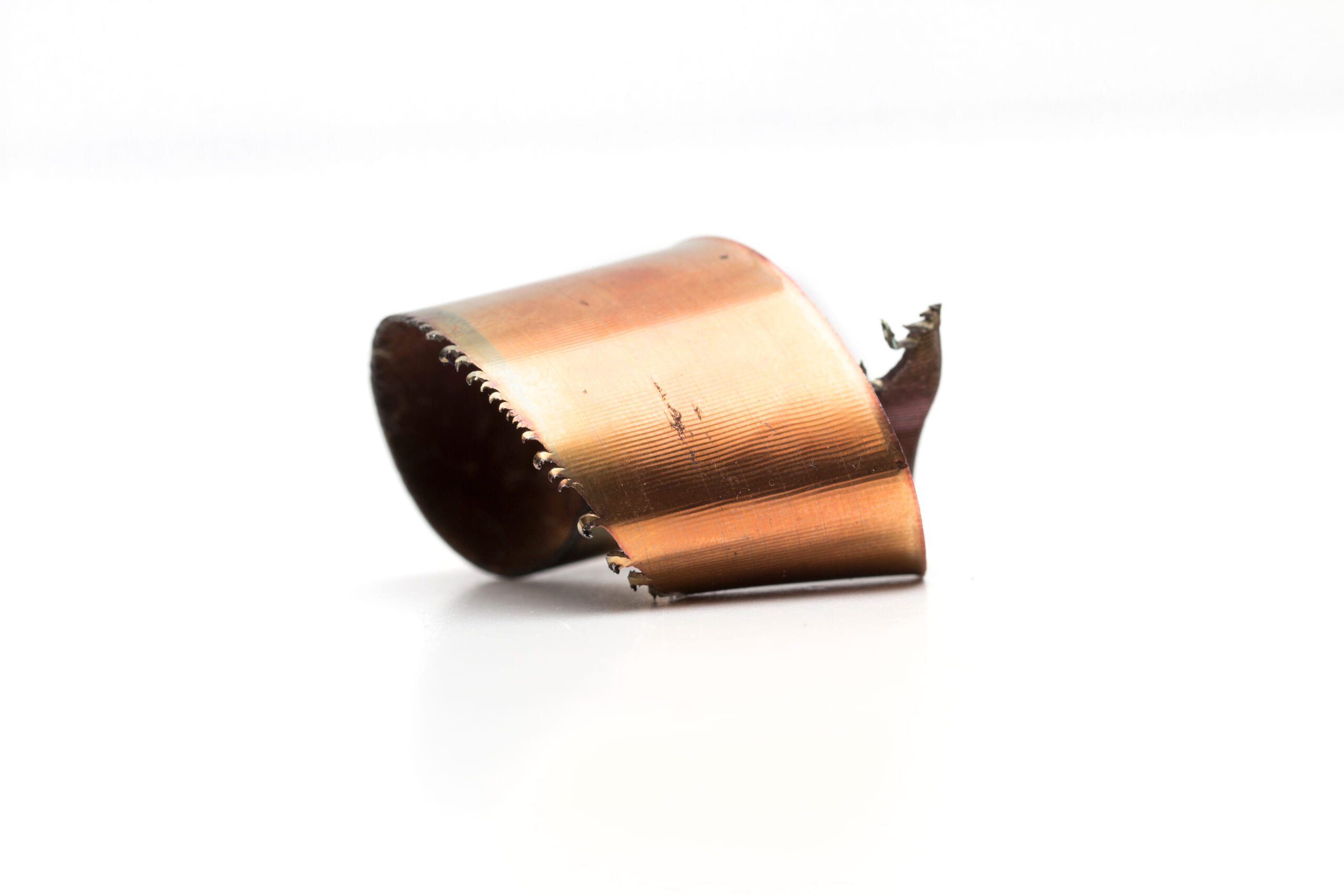
These chips become saw-tooth shaped because localized shear bands form alternately during cutting.
They often occur when cutting difficult-to-machine, low-thermal-conductivity materials—such as titanium alloys or austenitic stainless steels—at moderate speeds, producing jagged chip cross-sections.
These serrated (semi-continuous) chips form as the material locally softens and hardens repeatedly during machining, and can also indicate an unstable cutting process.
As described above, chip form is determined by the work material properties (ductility, brittleness, thermal characteristics, etc.) and cutting conditions (cutting speed, feed, tool geometry, friction conditions, etc.). On the shop floor, observing and classifying chips helps evaluate machining quality and optimize cutting conditions.
High-precision seating confirmation of workpiece and jig
- Air Gap Sensor -
You can check not only "presence/absence" but also "adhesion (gap)" at the same time with a repeatability of ±0.5 μm.
Click here ›Chip Formation Mechanisms and Their Relationship to Cutting Conditions
How chips are generated (the chip formation mechanism) is strongly influenced by the work material characteristics and the cutting conditions.
Chips are produced as material is removed by shear deformation, and their shape and size are mainly affected by the following factors.
Material Ductility and Brittleness
Ductile materials tend to plastically deform and form continuous chips, while brittle materials tend to fracture into small pieces, producing discontinuous chips.
For example, cast iron and brass often produce short chips that crumble during machining, whereas aluminum and low-carbon steel can produce long, coiled chips when machined at high cutting speeds with a smooth cutting edge.
With materials that conduct heat poorly, such as titanium alloys, periodic formation and disappearance of shear bands can result in serrated chips.
Cutting Speed and Feed (Cutting Conditions)
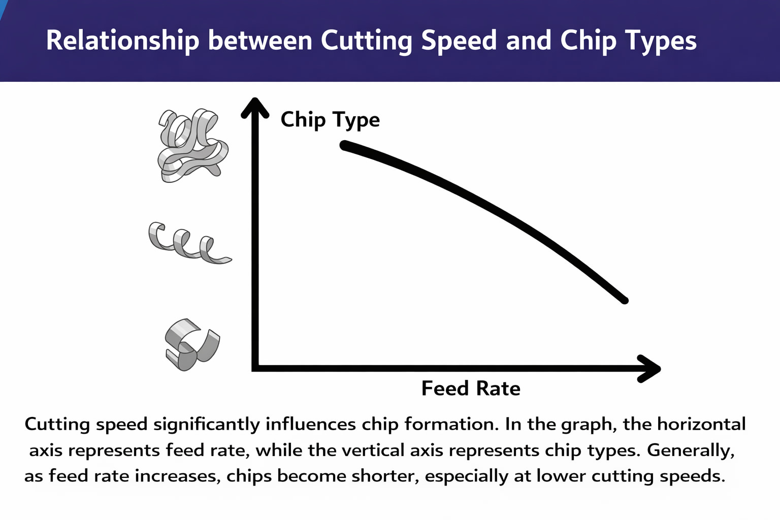
Cutting speed and feed also influence chip form.
In general, high speed with low feed tends to produce thin, long chips, while low speed or high feed tends to produce thicker chips that break more easily.
If the feed is excessively small, chips can become extremely thin ribbon-like strips that are hard to break, concentrating load at the tool tip and potentially accelerating tool wear.
Conversely, if the feed is too large, chips become thick—sometimes described as “square chips”—which also overloads the tool and shortens tool life.
Therefore, it is important to set an appropriate feed so chips break into manageable sizes. In practical machining, when the depth of cut is fixed, adjusting feed is often considered the most practical method of chip control.
Tool Geometry and Sharpness
The tool’s rake angle and cutting-edge geometry also affect how chips break.
Tools with a large rake angle and sharp edge tend to evacuate chips smoothly and continuously, while tools with a chip breaker apply forced bending to the chip, making it easier to break into shorter pieces.
Negative-rake tools (small/negative rake angle) tend to reduce the chip’s bending radius and produce shorter chips, while positive-rake tools tend to produce longer chips. Chip-breaker grooves near the tool tip intensify chip curvature, effectively segmenting long chips into smaller pieces.
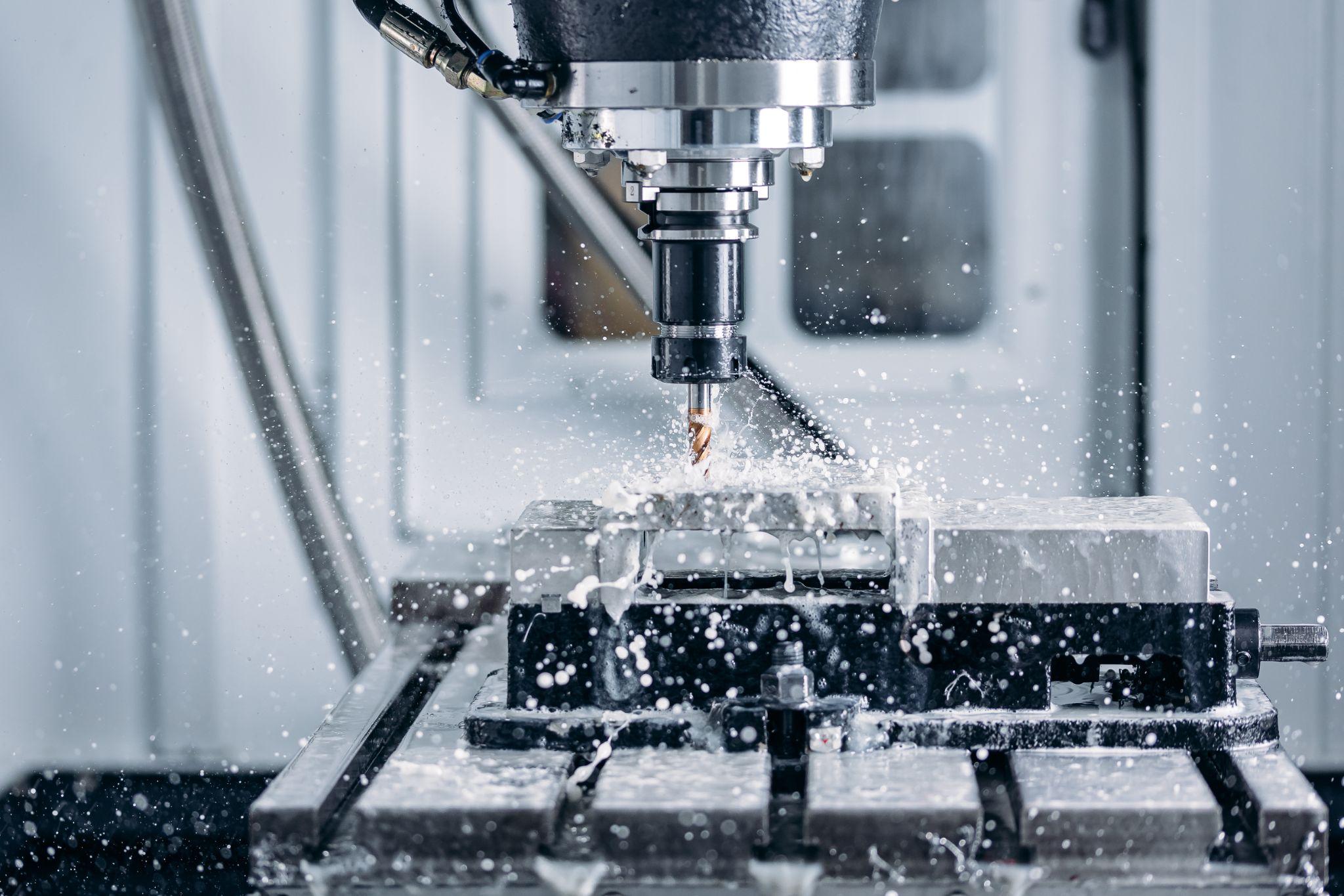
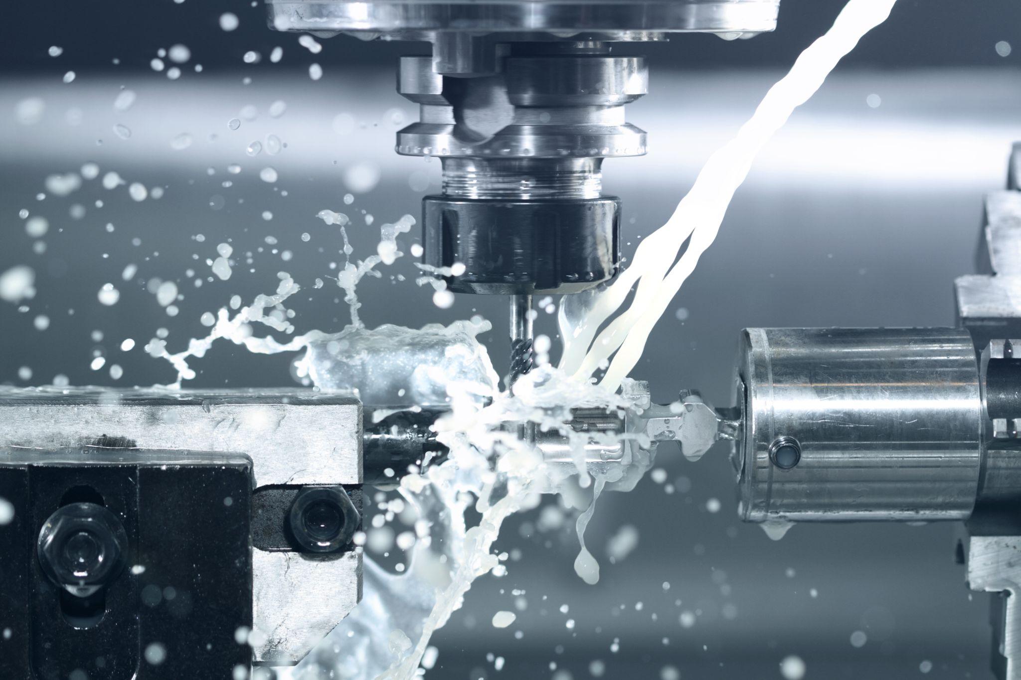
Cutting Fluids and Cooling Conditions
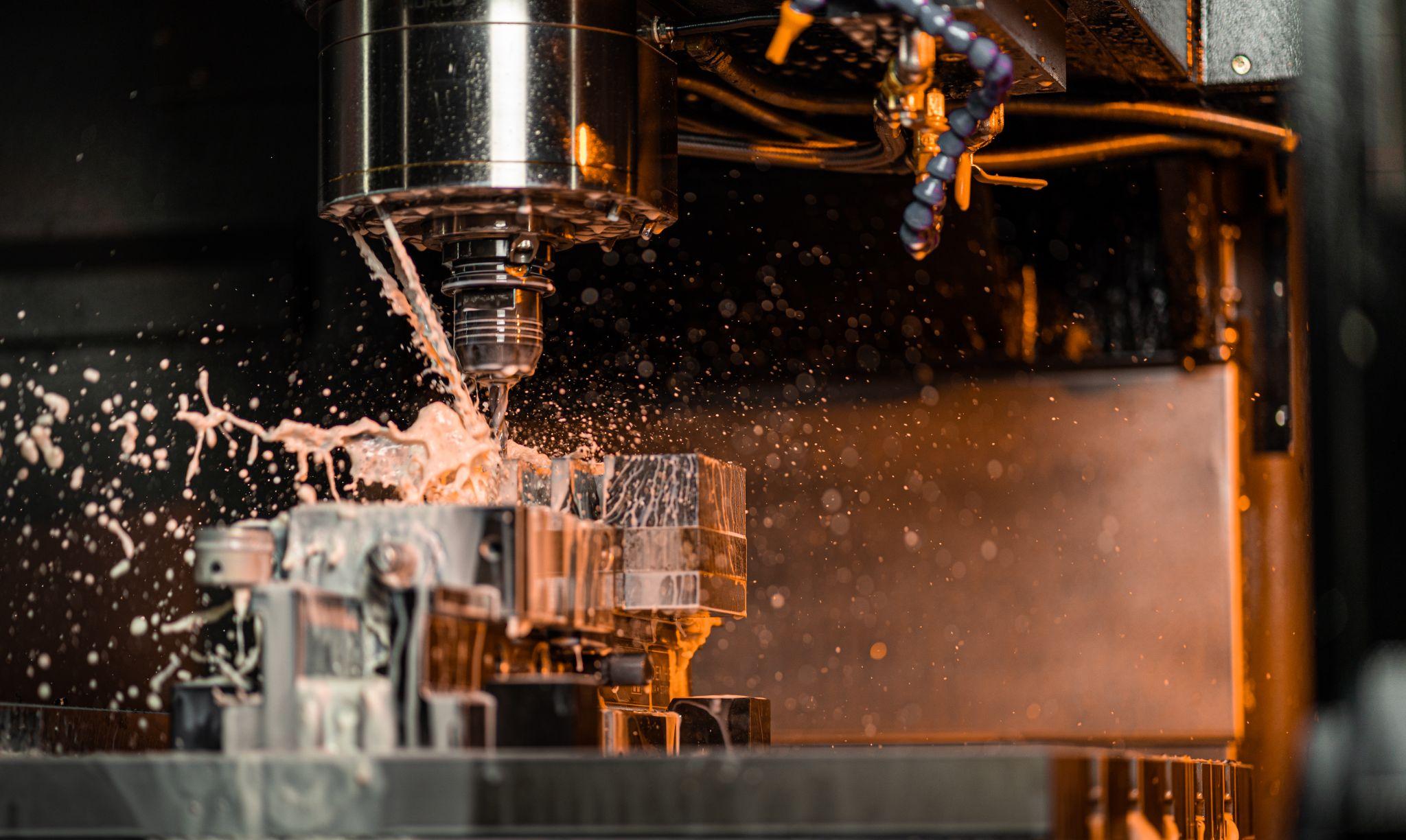
Cutting fluids (coolant) used during machining can also affect chip formation.
While standard cooling does not usually cause a dramatic change in chip form, specialized coolant delivered at high pressure in a targeted direction (e.g., high-pressure direct-jet coolant) can rapidly cool and fracture chips, helping break them into shorter lengths.
Proper cooling also suppresses frictional heat and built-up edge formation, contributing to smoother chip formation and more stable machining.
As shown above, chip formation is determined by a combination of multiple factors.
Shop-floor engineers select tools and adjust conditions to achieve the desired chip form. Typical measures include “increase feed to make long, tangled chips easier to break” and “increase cutting speed when built-up edge occurs.”
By observing chip color and shape during machining, you can also infer cutting-point temperature and load conditions, helping judge whether the settings are appropriate.
Chips are not merely waste—they act as a “mirror” of the machining process and provide valuable information.
High-precision seating confirmation of workpiece and jig
- Air Gap Sensor -
You can check not only "presence/absence" but also "adhesion (gap)" at the same time with a repeatability of ±0.5 μm.
Click here ›Chip Handling Methods and Reuse Technologies
In manufacturing, various practices and technologies are used to handle chips safely and efficiently, and to recover them as resources as much as possible.
Below are the main methods for chip handling and reuse.
Collection at the Source (Chip Collection)
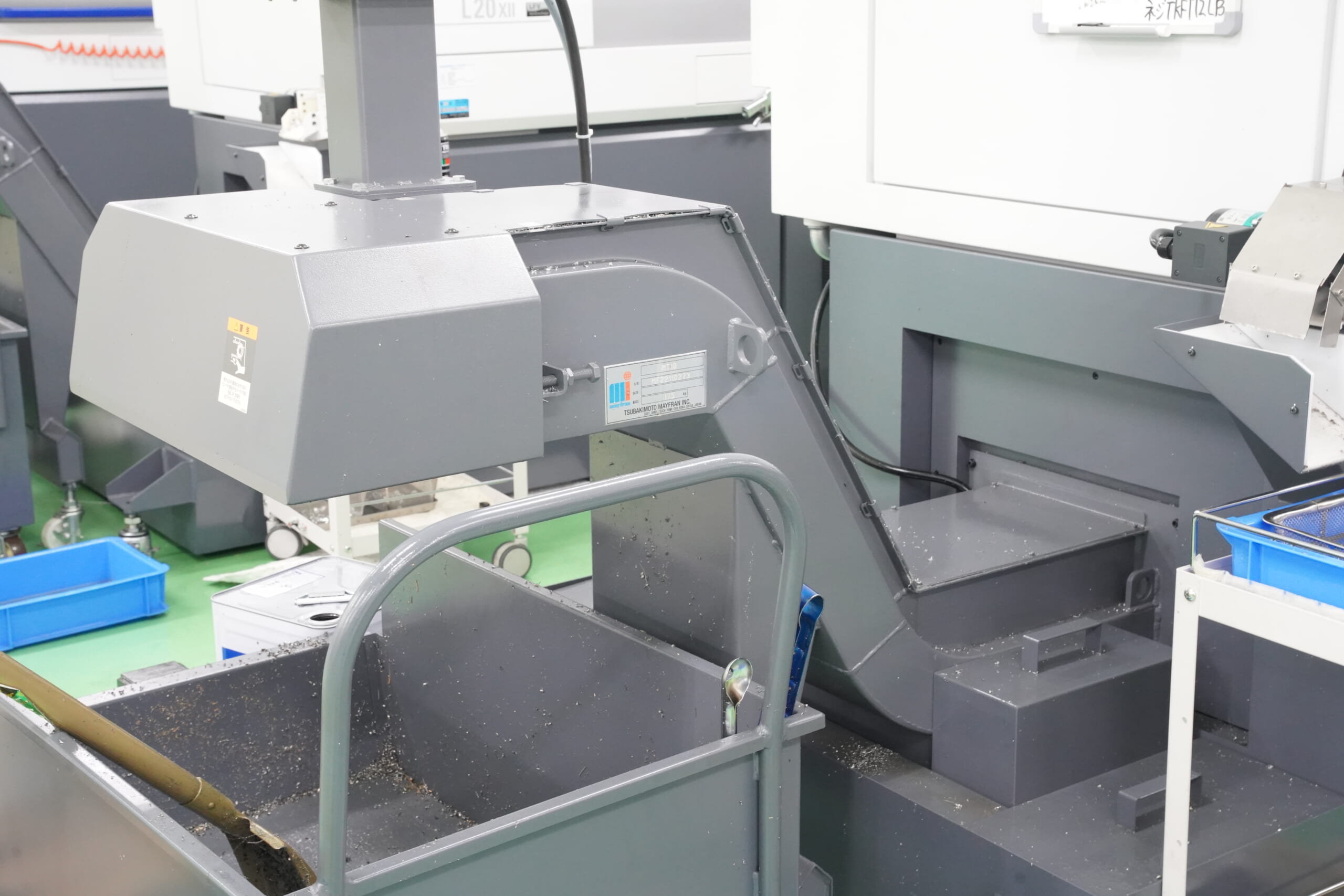
First and foremost, it is important to promptly collect chips generated by machine tools from inside the machine and the work area.
Many CNC machines are equipped with a chip conveyor that automatically transports chips to an external collection bin. For equipment without a conveyor or in manual processes, operators collect chips into collection boxes or lidded buckets.
For fine chips and dust, dust collectors and vacuum suction systems are also used.
These collection practices help prevent scattering and accumulation, keeping the work environment clean.
Sorting and Separate Storage
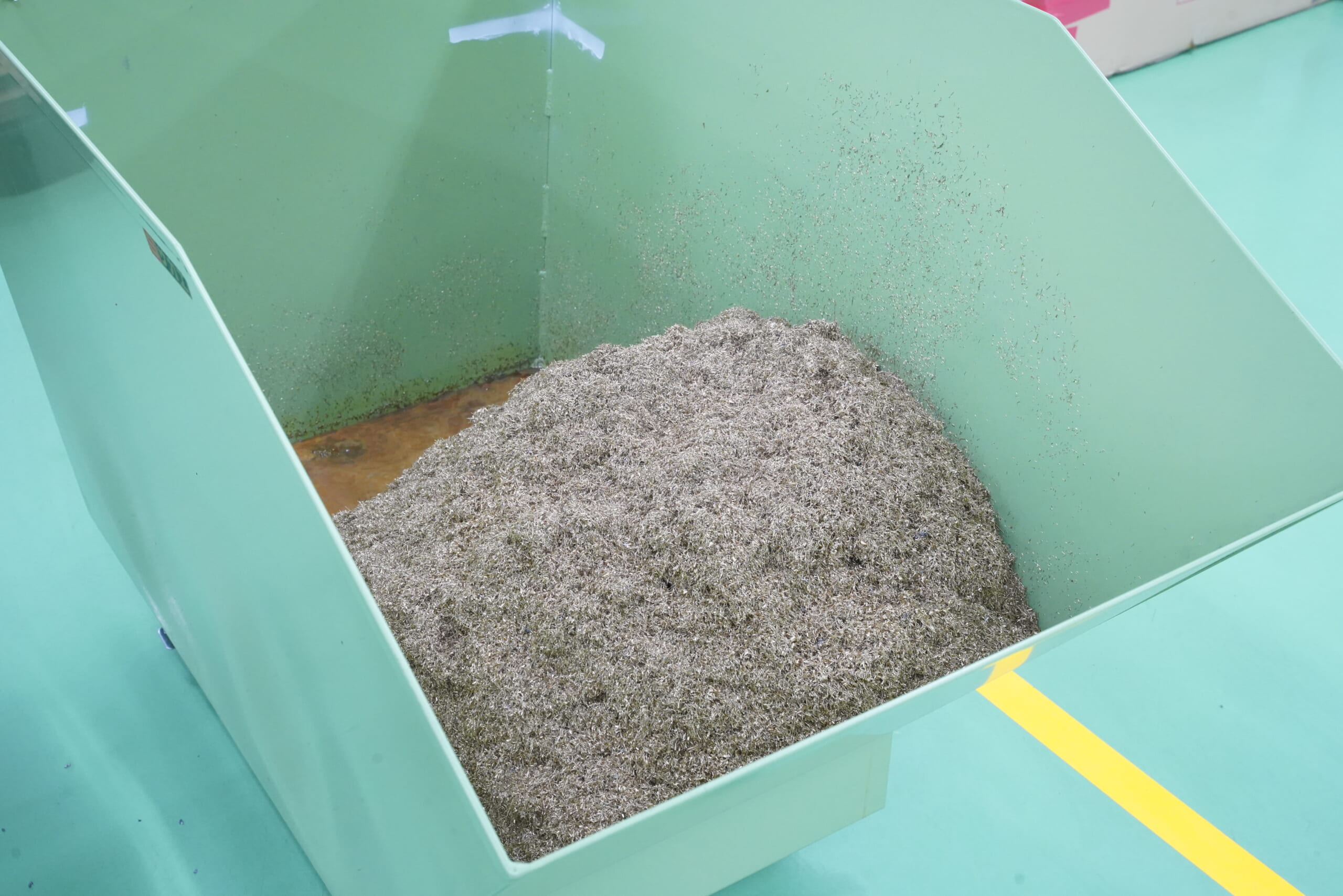
It is recommended to separate collected chips by material type.
Sorting chips into steel, aluminum, copper alloys, and other categories can increase their assessed value (scrap price) and prevent value loss due to mixed materials.
Wet chips (with cutting oil/coolant) should also be stored separately from dry chips.
Chips containing a large amount of oil can produce foul odors or pose a fire hazard if left as-is, so measures are needed—such as collecting them in funnel-top drums to drain oil, or using drip pans to capture oil.
Oil Removal and Volume Reduction
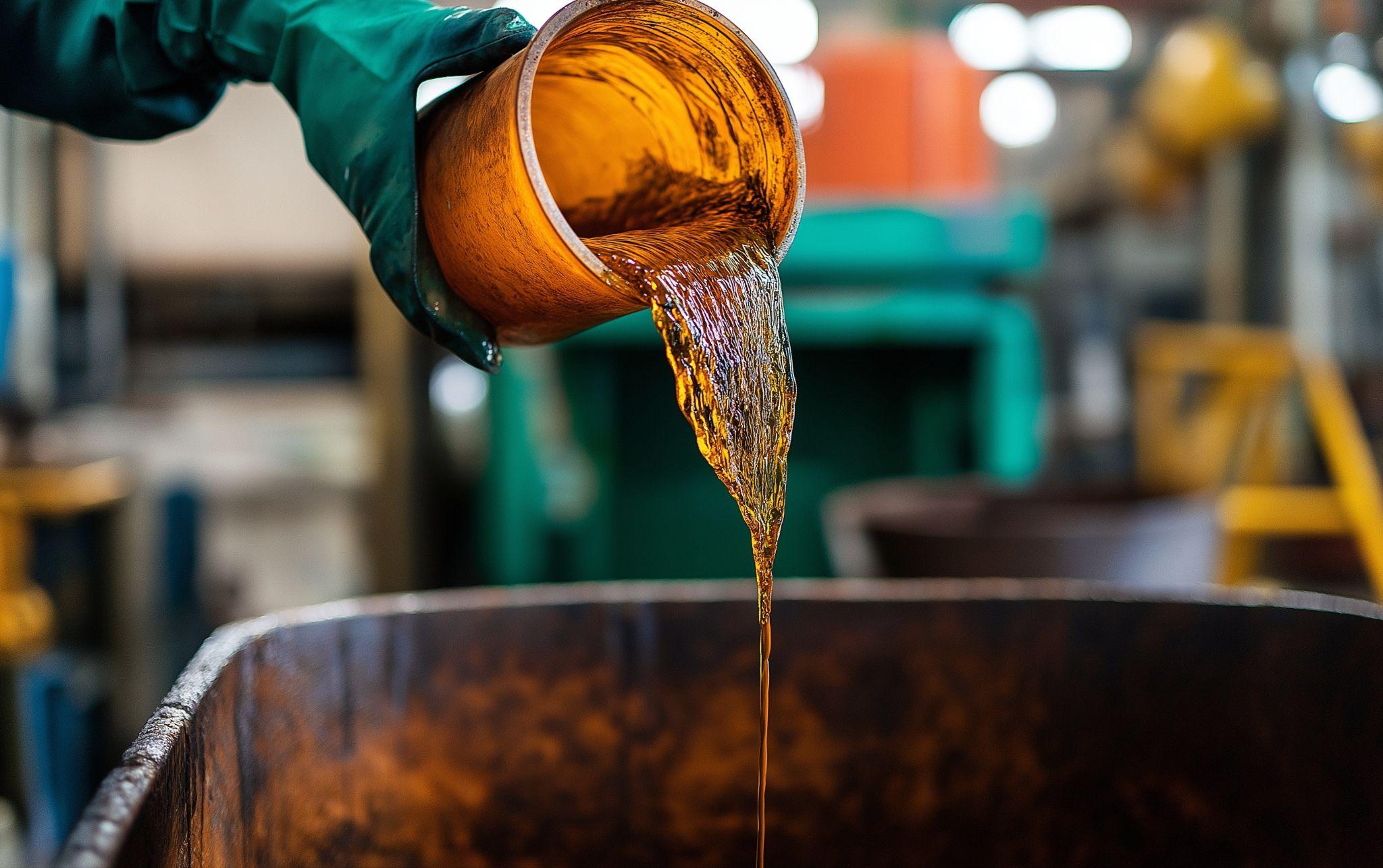
Various devices are used to recover cutting oil/coolant from chips and reduce chip volume.
Typical examples include centrifuges (chip spinners) and briquetting presses (briquette machines).
A chip spinner rotates chips in a basket at high speed to fling off oil via centrifugal force for recovery. A briquetting press compresses chips under high pressure into solid blocks (briquettes).
This significantly reduces chip volume, making storage and transport easier, while also enabling reuse of the cutting oil squeezed out during compression.
For example, one manufacturer introduced a chip briquetting system, reducing new oil consumption through recovery and reuse, and cutting chip volume to one-fifth or less.
Compressed chip briquettes are drier and easier to handle, improving efficiency in subsequent melting and recycling processes.
Chip Crushing (Chip Crusher)
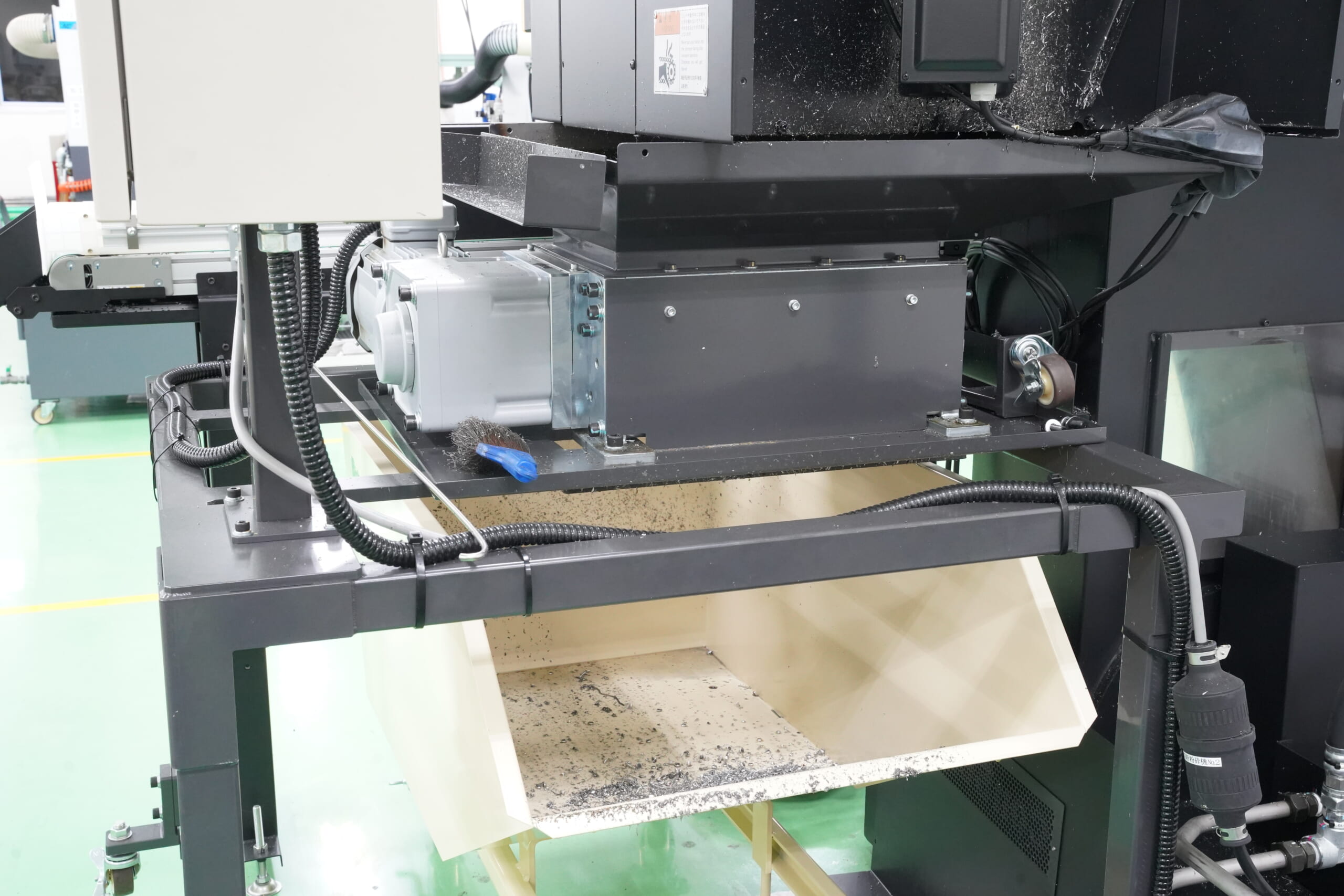
For long, stringy chips generated in turning and similar processes, chip crushers are used to break them into shorter pieces.
A chip crusher works like a shredder, using cutters to chop long chips traveling on a conveyor into smaller pieces.
The crushed chips become a manageable particle size that can be handled with a shovel and are less likely to clog downstream equipment (such as spinners or briquetting presses).
Crushing reduces the risk of long chips wrapping around components and stopping the machine, and it helps increase the level of automation in chip handling.
Coolant Filtration and Regeneration
It is also important to recover, purify, and reuse cutting fluids (coolant) discharged together with chips.
Coolant circulated in a machine tank gradually becomes contaminated with fine chip particles, so filters and magnetic separators are used to remove chips and extend coolant life.
If filtration is inadequate, internal piping can clog and pumps may fail, so regular coolant management is essential. It is also becoming common to filter and settle recovered oil/coolant from spinners or briquetting presses so it can be reused and returned to the machine, reducing the amount of new fluid needed.
Such coolant recycling contributes to both cost reduction and lower environmental impact.
Recycling as a Metal Resource
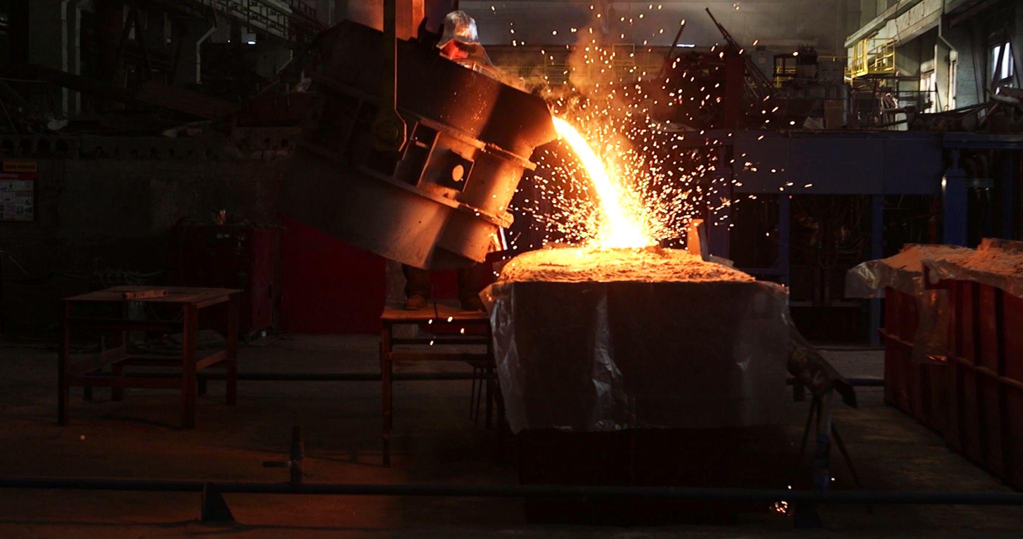
Metal chips that have been collected and volume-reduced are ultimately recycled at steelworks and non-ferrous metal smelters.
Ferrous chips are melted in furnaces together with other steel scrap and become raw material for new steel products.
Aluminum chips are also melted into ingots and reborn as castings or rolled products.
In recent years, more efforts have focused on thoroughly removing cutting oil and controlling material purity to increase the value of chips as high-quality recycled metal.
In some cases, chips are washed and dried before being press-compressed to reduce residual oil and shipped as high-purity metal briquettes.
As another reuse approach, research is underway to produce metal powder from chips for powder metallurgy and metal 3D printing (e.g., using ball milling to pulverize chips into powders with a specified particle size).
With these advanced recycling technologies, momentum is growing to utilize chips as part of a circular resource system.
As outlined above, chip handling typically follows a process of collection and sorting → oil removal and volume reduction → recycling, and dedicated equipment and technologies have evolved for each step.
By combining these steps appropriately, factories can handle chips safely and efficiently and recycle chips as valuable materials.
Advancing chip handling is an important theme tied not only to cost reduction but also to lower environmental impact and corporate social responsibility (CSR).
High-precision seating confirmation of workpiece and jig
- Air Gap Sensor -
You can check not only "presence/absence" but also "adhesion (gap)" at the same time with a repeatability of ±0.5 μm.
Click here ›Practical Knowledge and Design Considerations About Chips for Manufacturing Engineers
Chips are often seen as a shop-floor issue, but by considering chips early—during product and process design—you can prevent downstream trouble and improve productivity.
Below is a summary of practical chip-related knowledge and considerations useful for designers and engineers.
Shape Design that Facilitates Chip Evacuation
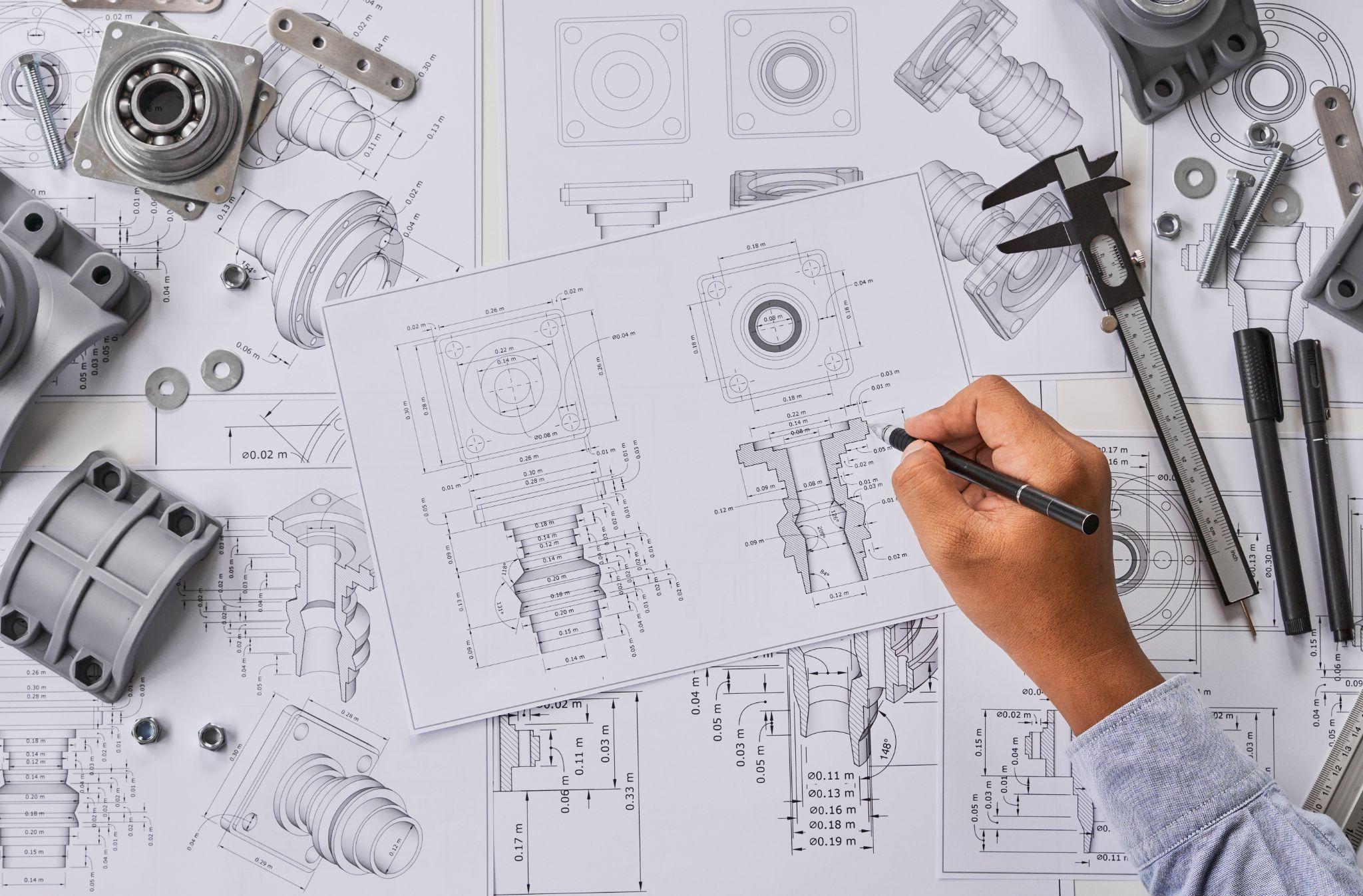
When designing product or part geometry, aim for shapes that minimize chip retention during machining.
Avoid deep pockets and blind holes where possible; using through holes and providing sufficient relief angles makes chip evacuation easier during drilling.
Likewise, making threaded holes through-type where feasible and adding corner radii to complex corners to reduce chip trapping can help prevent machining defects caused by chip clogging.
It is also effective to consider part orientation and fixture positioning during design so chips can naturally fall away under gravity during machining.
By addressing these points in design, you can reduce shop-floor issues such as “chips can’t be fully removed, so rework is required.”
Selecting Machining Methods and Cutting Conditions
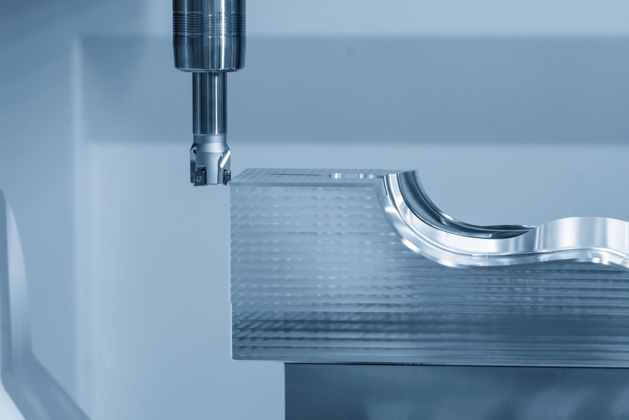
When designing the manufacturing process, consider what kind of chips the selected method will generate.
For example, instead of milling a part from solid stock and generating a large volume of chips, it may be better to cast or forge a near-net shape and then perform finish cutting—reducing chip volume and improving material yield.
Thin, deep holes can clog with chips if drilled in one shot, so process options include stepwise peck drilling, switching to EDM, or designing long workpieces so drilling can start from an intermediate point—process ingenuity can help avoid chip-related problems.
In tool selection, using inserts with chip breakers or tools designed for high-pressure coolant can make it easier to control chips into shorter lengths.
Rather than leaving cutting conditions entirely to the machine or operator, it can be useful to specify optimal conditions already at the process-design stage.
With an appropriate combination of depth of cut and feed rate, you can achieve “chip control” that stabilizes machining without producing chips that are excessively long or overly short.
By working with machining personnel and incorporating key cutting-condition guidance into drawings and process sheets, designers can build machining plans that reduce chip-handling headaches on the shop floor.
Chip-Related Troubleshooting Measures Used on the Shop Floor
In cutting processes that remove material to create a desired shape, it is not possible to eliminate chip-related issues entirely.
However, beyond selecting cutting conditions and tools as described above, you can minimize problems through machine selection, clamping methods, and capital investment.
Below are examples of chip-related countermeasures adopted in actual shops.
For Deep-Hole Work or High-Volume Chip Generation, Consider Horizontal Machining
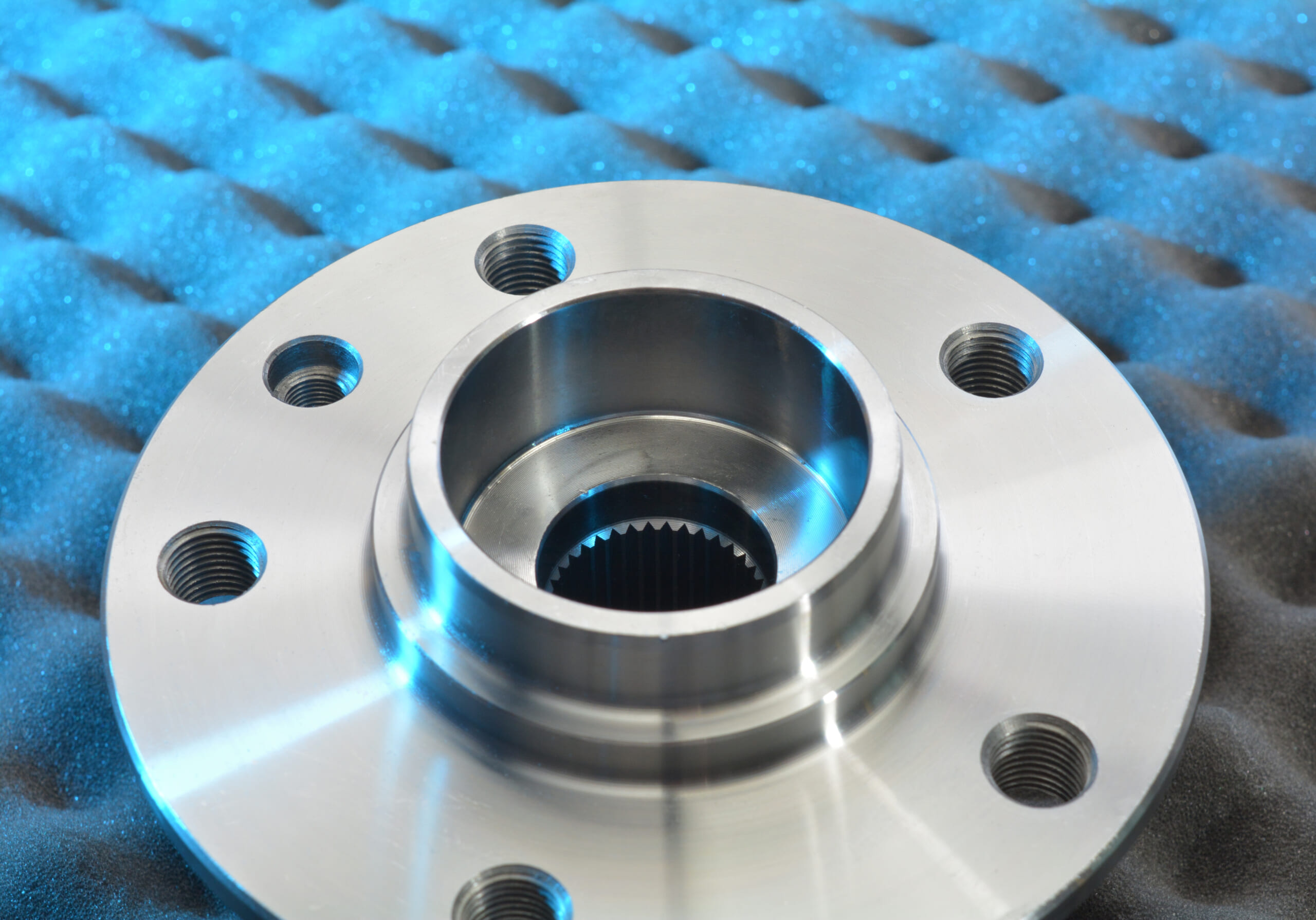
If you already have a horizontal machining center in-house, it is recommended to switch machines for deep-hole machining or parts that generate a large volume of chips.
With a horizontal machining center, the spindle moves in a direction parallel to the ground, which makes it less likely for chips to accumulate on the top surface of the workpiece (the surface facing the spindle).
As a result, the risk of the drill tip pulling chips into the hole is lower, and the risk of tool breakage due to chip biting is reduced compared with vertical machines.
Another advantage is that even when machining parts that generate many chips, chips are less likely to pile up on the workpiece surface—so face milling tends to suffer less chipping or breakage caused by chip biting.
In practice, switching from a vertical to a horizontal machine significantly reduced tool breakage in deep-hole machining, eliminated frequent table cleaning caused by chip buildup, and also reduced face-mill insert damage.
Use Shower Coolant to Prevent Telescopic Cover Damage Caused by Chip Accumulation
Many horizontal machining centers have the machining space covered by exterior guards, and chips generated by cutting are discharged outside via a chip conveyor.
However, depending on tool type/geometry and the feed direction during machining, chips may accumulate in locations where they are not easily carried to the chip conveyor.
As a result, chips can enter the gaps of internal dust covers (telescopic covers), impair movement, and frequently cause cover damage.
To address this, plumbing for “shower coolant” was installed inside the machining center so coolant would flow simultaneously with spindle rotation; the chips were washed away cleanly and telescopic cover damage was eliminated.
A drawback is that coolant washes away all internal grime, so the oil recovered by the oil skimmer can contain large amounts of sludge and contaminants. Even so, the approach helped avoid temporary production stoppages and expensive repair costs due to telescopic cover damage.
What Are Metrol’s High-Precision Positioning Sensors?
Chips generated in cutting can cause defects or tool breakage even with only a few micrometers of chip biting, making them a persistent challenge.
That is why sensor technologies that can accurately detect minute changes—such as whether a workpiece is properly seated, or the tool’s length and wear—become indispensable.
Metrol offers a high-performance lineup recognized worldwide, including contact switches with repeatability up to 0.5 µm and air micro sensors capable of detecting gaps under 10 µm with ±0.5 µm accuracy.
Below, we introduce representative Metrol sensors used on shop floors, along with their key features and roles.
High-Precision Positioning Touch Switches
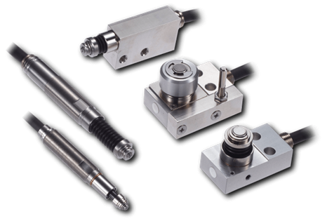
These are contact-type high-precision switches used for positioning and workpiece presence detection in machine tools, robots, and jigs. They achieve an extremely high repeatability of up to 0.5 µm and feature IP67-rated waterproof and dustproof protection, ensuring stable operation even in harsh environments. With more than 200 standard models available, they offer a wide range of variations, including designs for confined spaces, high-temperature environments, vacuum applications, and low contact force requirements.
Tool Setter (Tool Length Measurement Sensor)
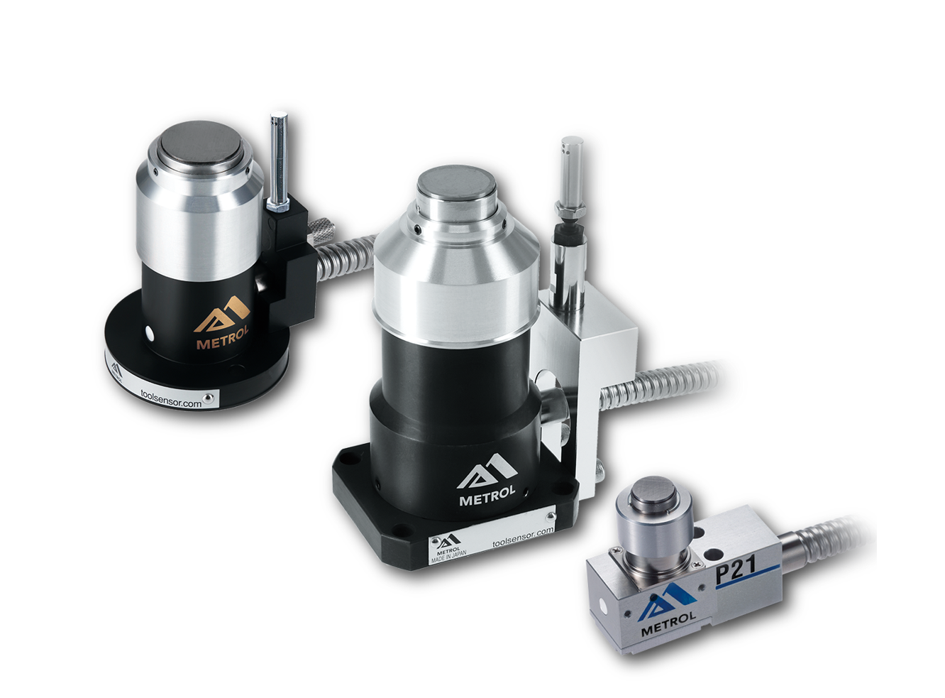
This is a contact-type sensor installed on CNC machine tools and industrial robots for tool length measurement, reference position setting, and tool breakage detection. By automatically measuring and compensating for tool length, wear, and thermal displacement inside the machine, it helps prevent machining defects and significantly reduces setup time. It is one of Metrol’s best-selling products, with a proven track record of more than 500,000 units shipped in 74 countries worldwide.
Touch Probe (On-Machine Measurement Probe)
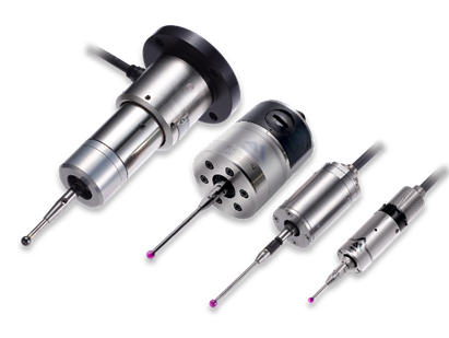
This is a contact-type probe for in-machine measurement, installed on machine tools and robots to automatically perform workpiece positioning (centering) before machining and dimensional measurement after machining. With a repeatability of 1 µm, it automates workpiece referencing and dimensional inspection, replacing skilled manual operations to reduce setup time and help prevent machining defects. Both wired and wireless models are available, meeting retrofit needs for 5-axis machining centers and robotic applications.
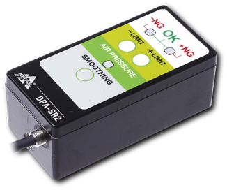
Air Gap Sensor (Pneumatic Sensor)
This is a non-contact sensor that uses air pressure to detect workpiece seating conditions with micron-level accuracy. It can detect gaps (“lift”) of less than 10 µm—previously difficult to measure—with a repeatability of ±0.5 µm, helping prevent machining defects and equipment downtime caused by insufficient contact between the workpiece and fixture. The sensor is used in applications such as semiconductor manufacturing processes, precision part clamping operations, and grinding wheel positioning on grinding machines, and it is a smart sensor that also supports the international standard IO-Link communication.