What Is “Seating” in Machine Tools? Methods, Measurement, and Key Design Considerations
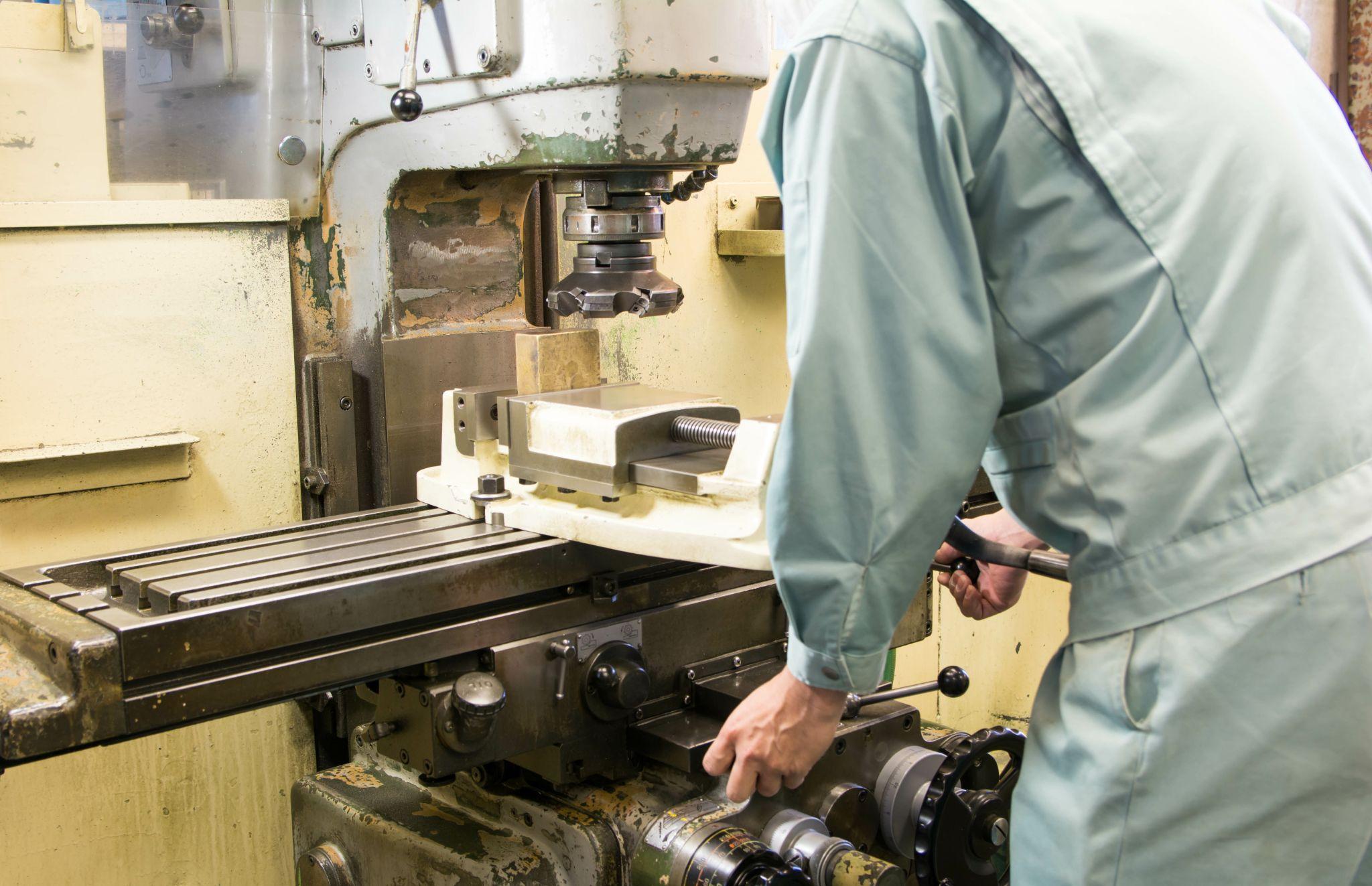
Proper workpiece seating is essential for producing high-precision parts on the shop floor.
No matter how capable the machine tool or cutting tool is, machining accuracy will not be stable unless the workpiece is firmly seated against the fixture or table.
“Seating” refers to accurately positioning and securing the workpiece in the specified location and orientation, and it directly affects dimensional accuracy, surface roughness, and even tool life.
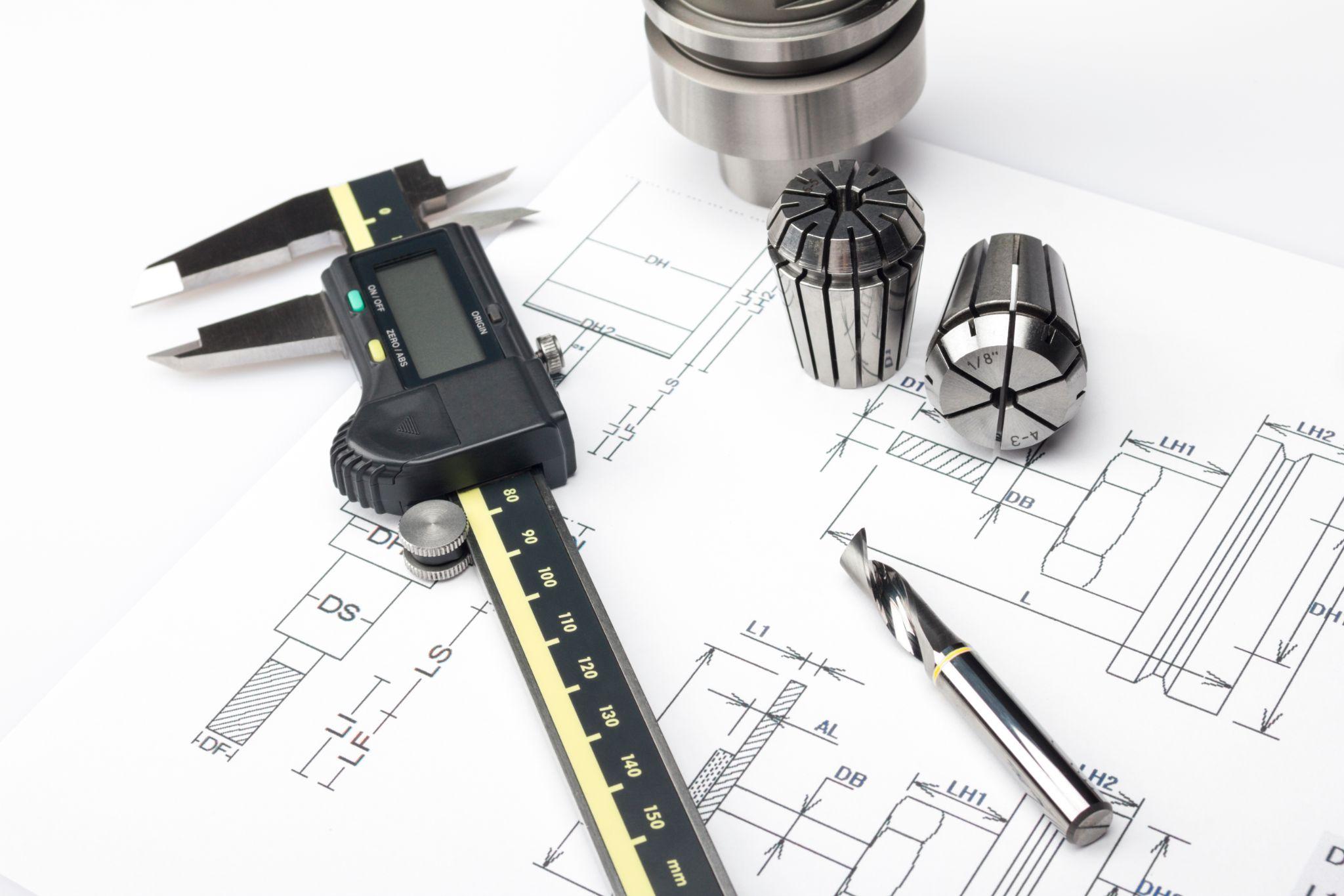
This article clearly explains seating from both shop-floor and design perspectives—its definition, the impact of poor seating, common methods to ensure it, measurement/verification approaches, and key design considerations.
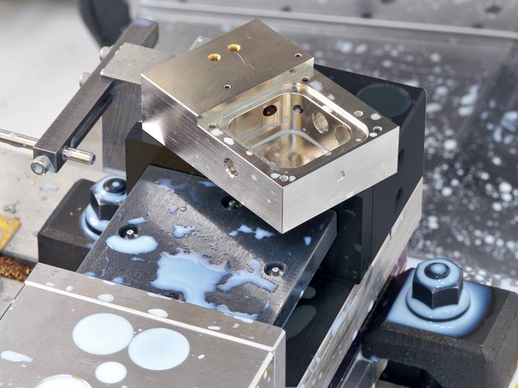
High-precision seating confirmation of workpiece and jig
- Air Gap Sensor -
You can check not only "presence/absence" but also "adhesion (gap)" at the same time with a repeatability of ±0.5 μm.
Click here ›Table of Contents
Definition of Seating and Why It Matters
In machine tools, “seating” means accurately placing and securing the workpiece in the specified position and orientation so that it does not move during machining.
In other words, it is the act of properly setting the workpiece on the fixture or table. Whether seating is done correctly has a direct impact on machining accuracy and quality.
In fact, it is often said that “the dimensional accuracy of the finished part is proportional to the clamping device and how it is used,” underscoring how critical workholding is.
Locating and clamping are the core of workholding; without stable, repeatable fixation of the workpiece at the intended position, high-precision machining cannot be achieved.
In short, even with high-performance machines and tools, insufficient workpiece seating will lead to unstable machining accuracy.
How Poor Seating Affects Machining Accuracy
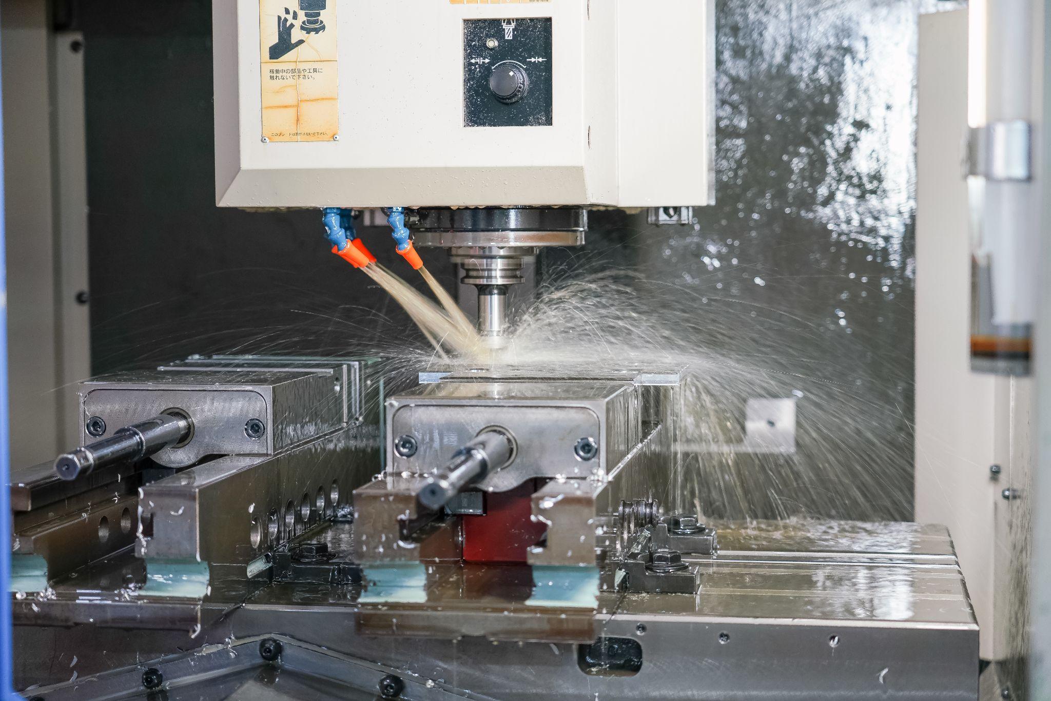
If the workpiece is not properly seated (poor seating), it can cause positional shift, vibration, and dimensional errors during machining.
For example, if chips or burrs get trapped on the fixture or table and lift the workpiece, even a gap of only a few microns can lead to machining errors.
In high-precision machining, even about 10 µm of lift (a gap) caused by chip entrapment can degrade final accuracy, so strict seating verification—using pneumatic sensors, for example—is required.
If the workholding is insufficient, even slight movement during machining can reduce dimensional accuracy, worsen surface roughness, and damage tools.
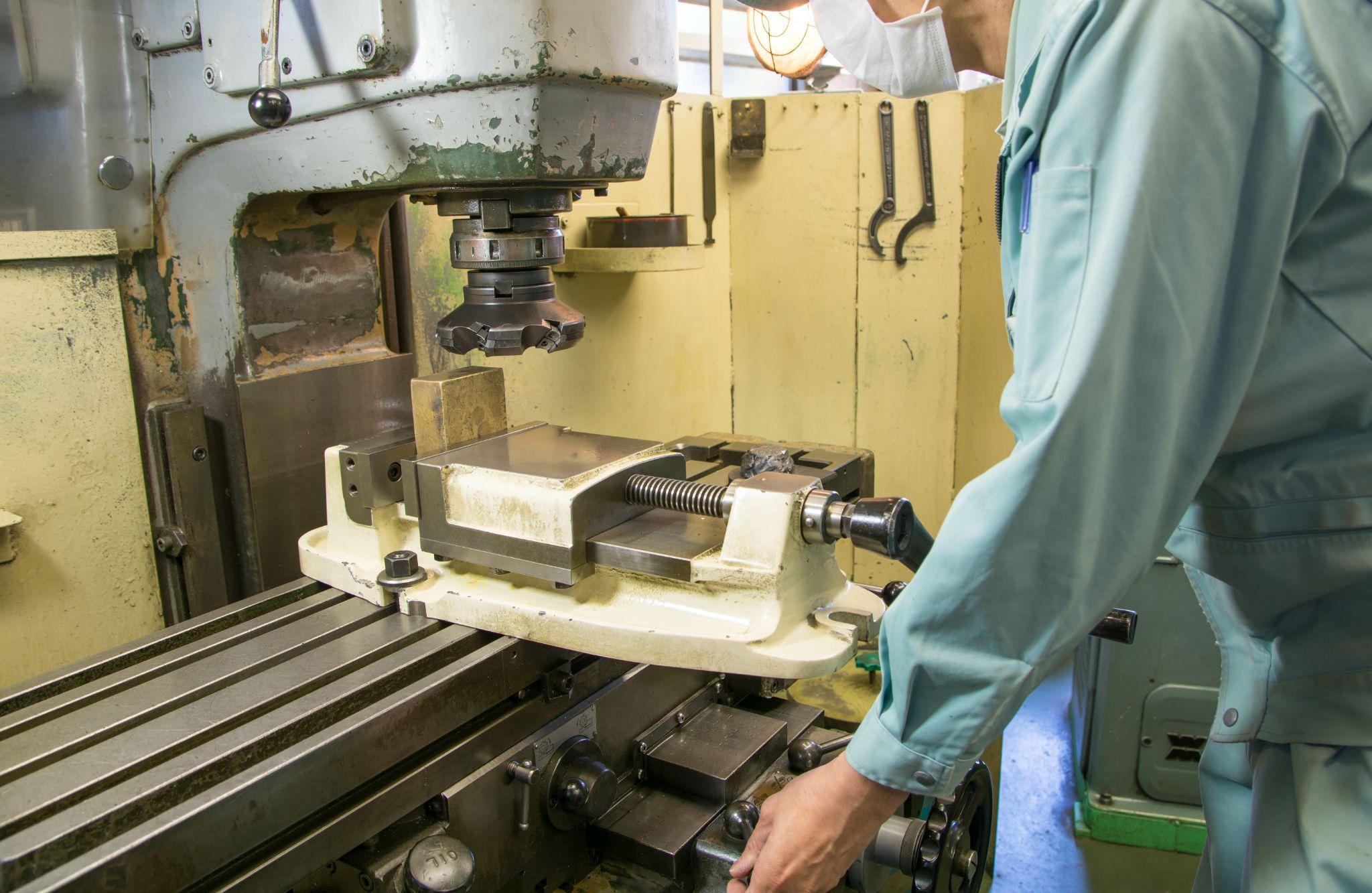
In extreme cases, if a machine vise is of poor quality, the movable jaw may slightly rotate or lift during tightening, causing part of the workpiece to lift and tilt.
When the workpiece lifts off the parallels like this, the depth of cut can vary and positional errors can occur, resulting in poor accuracy or parts falling outside dimensional tolerances.
A common shop-floor rule of thumb is: “If the workpiece is properly seated, the parallel blocks under the vise won’t move when pushed with a finger.”
Whether seating is good or bad is one of the key factors that determines machining success.
High-precision seating confirmation of workpiece and jig
- Air Gap Sensor -
You can check not only "presence/absence" but also "adhesion (gap)" at the same time with a repeatability of ±0.5 μm.
Click here ›Common Ways to Ensure Proper Seating
To achieve stable seating, you need a combination of proper locating and reliable clamping.
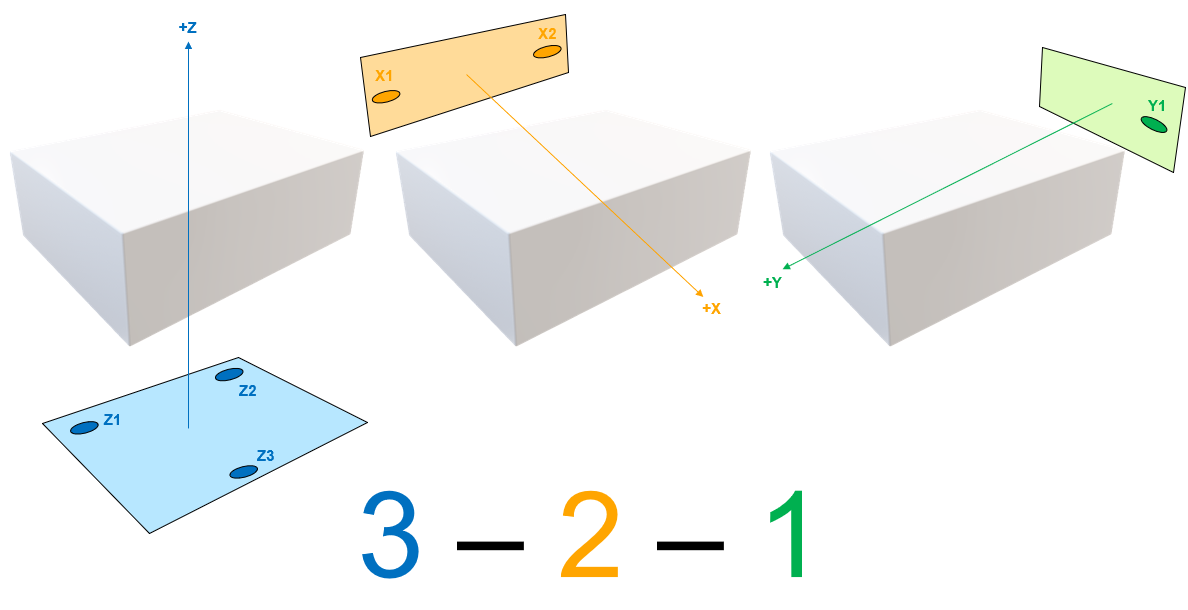
The “3-2-1 locating principle” is commonly used: six support/locating elements constrain the workpiece’s six degrees of freedom (translation and rotation along the X, Y, and Z axes).
Below are typical elements used to ensure stable seating.
Datum Surfaces and Support Points
Provide a datum (support) surface on the fixture to support the underside of the workpiece.
Typically, the workpiece is supported at three points (using three support pins or blocks), which stabilizes it on a plane and prevents rocking. With three-point support, all points inevitably contact, creating a stable datum plane on the underside of the workpiece.
Locating Pins (Datum Pins)
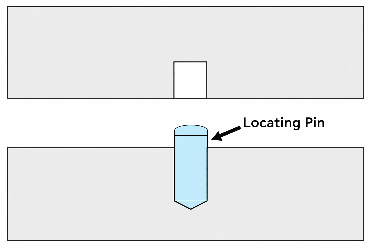
Use locating pins that correspond to the workpiece’s side surfaces or holes to prevent shifting in the X and Y directions. Typically, two pins locate the side (two points constrain rotation), and an additional pin or stopper locates the end face.
By establishing these locating references, you improve repeatability so the workpiece can be mounted in the same position every time.
Clamping Devices (Clamping Mechanisms)
To firmly secure a workpiece placed in position, use clamps to hold it down. Common options include toggle clamps, screw clamps, hydraulic/pneumatic clamps, and vises.
The key is not only tightening but ensuring sufficient downward holding force. Proper clamping prevents vibration and shifting during machining and keeps the workpiece in the intended position.
Fixture Design Techniques
The fixture’s stiffness and accuracy are also critical factors.
Many precision fixtures are available from fixture/tool manufacturers; for example, vacuum chucks (suction holding) and magnetic chucks (magnetic holding) can be effective for seating workpieces with special shapes.
There are also locating pins—such as tapered pins and expanding pins—designed to minimize play according to the tolerance of the workpiece holes.
Using these fixture elements appropriately helps reduce the risk of poor seating.
How to Measure and Verify Seating
Even after you believe seating is secured, verifying “Is it truly installed correctly?” is essential for quality assurance. The following methods and technologies are commonly used on the shop floor.
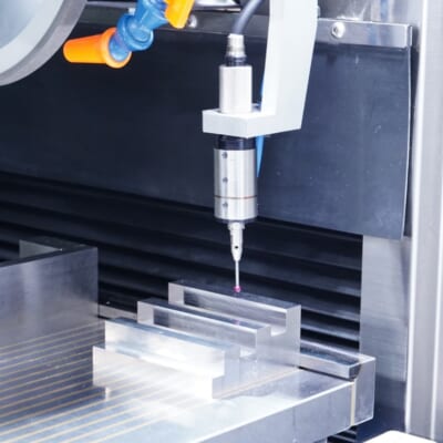
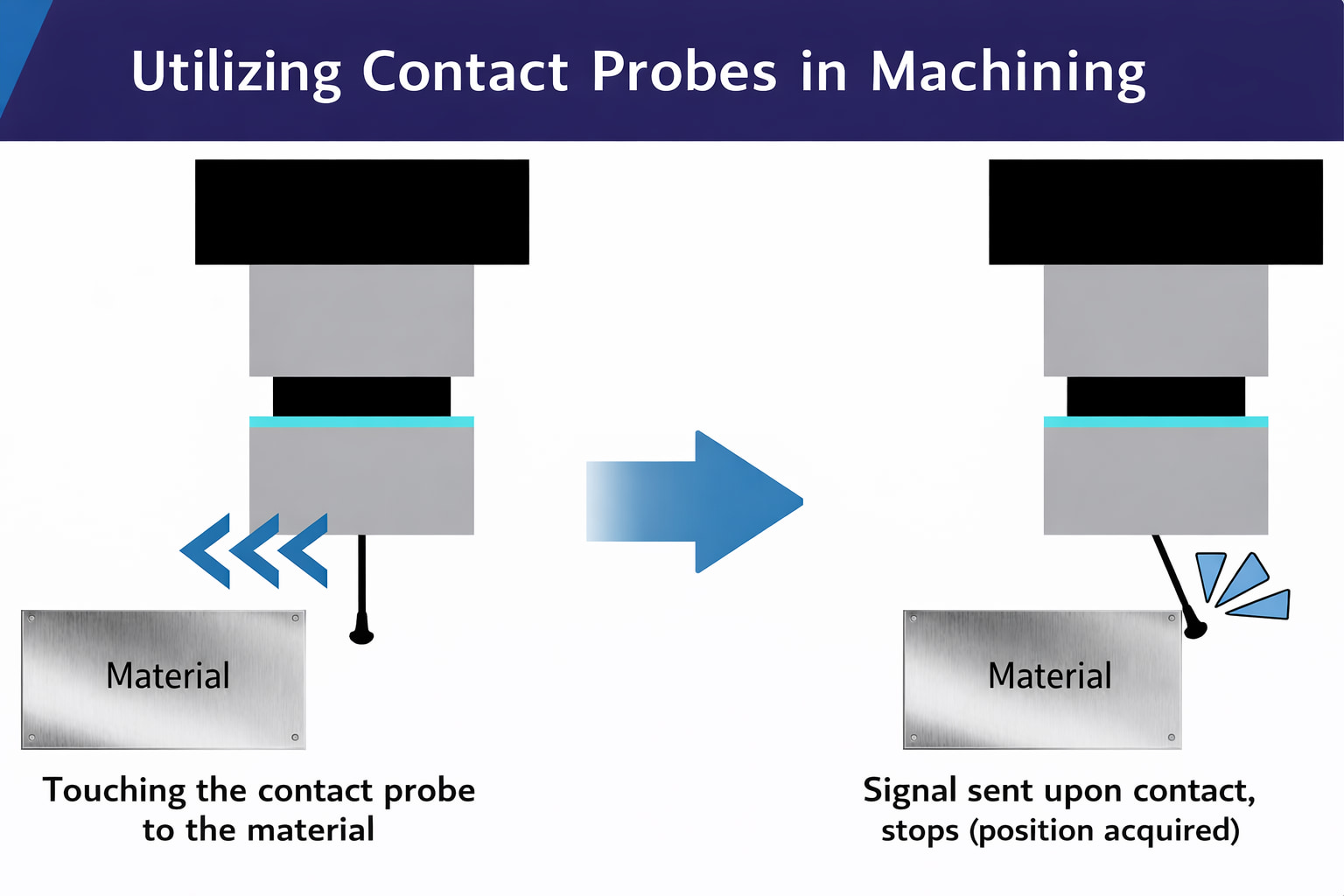
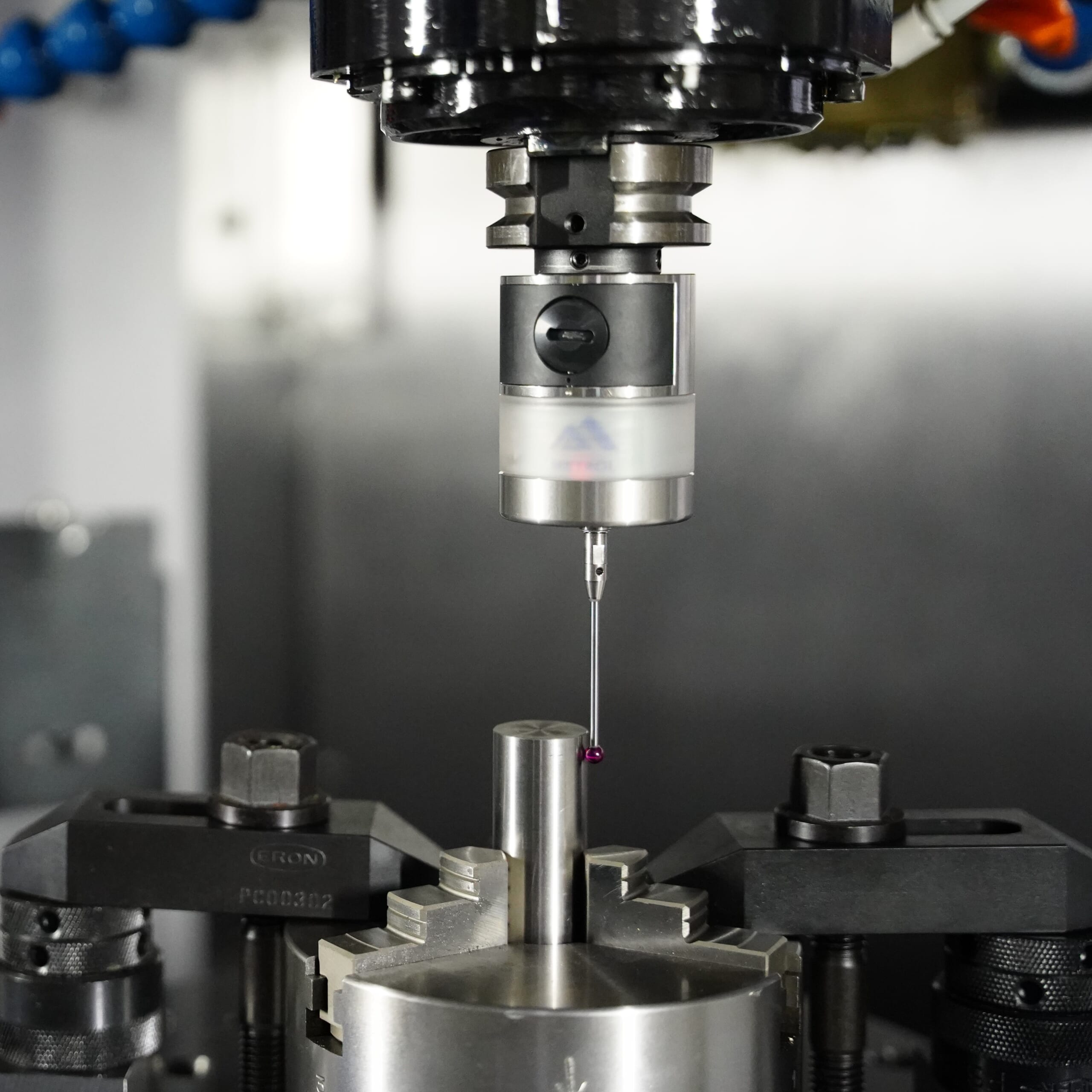
Verification Using a Probe
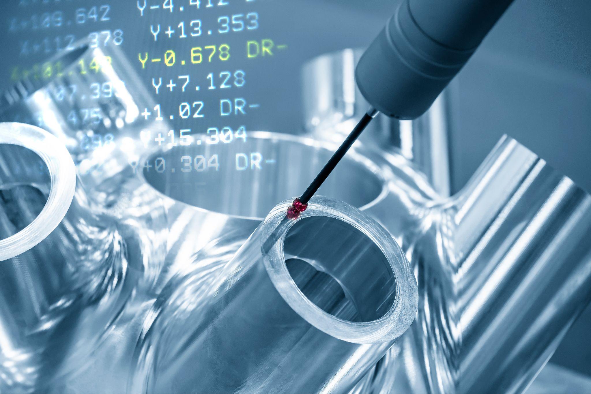
On CNC machine tools, touch probes can be used to measure the workpiece’s position and orientation. Before machining, the probe touches multiple points to check the height and location of the workpiece datum surface and confirm proper seating.
By leveraging on-machine measurement, real-time inspection before and after machining becomes possible, helping to prevent defective machining.
Probes can quickly verify the accurate position and dimensions of the workpiece and fixture, detecting misalignment and errors without relying on complex dedicated fixtures.
In practice, operations such as “detect the workpiece position with a probe for each cycle and apply compensation if there is an error” greatly contribute to process stabilization and improved confidence in unattended operation.
Automated workpiece centering and positioning
- Touch probe -
A contact/touch sensor for on-machine measurement that improves the efficiency of setup work
Click here ›Verification Using a Vision System
Another approach is to use a vision system (camera inspection equipment) to check workpiece placement. For example, a camera can capture and detect gaps between the workpiece surface and the fixture datum surface, or image recognition can determine whether the workpiece outline is within a specified range.
In automated transfer lines, robots may place the workpiece and then cameras capture images from above or the side to verify there is no tilt or lift-off.
Vision-based verification is non-contact and fast, and once acceptance criteria are prepared for each product, it can handle high-mix production relatively easily.
Verification Using Contact Sensors and Air Sensors
This method integrates sensors into the machine tool or fixture to detect the workpiece seating state mechanically or pneumatically.
One example of a mechanical sensor is a small spring pin (a spring-loaded contact) installed on the fixture datum surface; when the workpiece seats correctly, the pin is pushed in and the sensor turns ON. By monitoring contact at the four corners, you can even detect whether any corner of the workpiece is lifting.
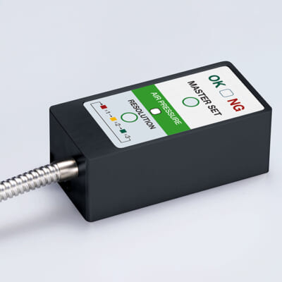
With a pneumatic approach (air micro sensors), small holes are added to the fixture datum surface to blow air, and the presence of a gap is determined from changes in back pressure.
Conventional general-purpose air sensors were mainly intended to detect the presence/absence of a workpiece, and in some cases were not sufficient for high-precision requirements.
In recent years, high-precision air gap sensors have emerged that can detect gaps under 10 µm with repeatability around ±0.5 µm, reliably finding even very slight lift caused by chip entrapment.
There are also reported cases where introducing high-precision sensors addressed shop-floor concerns such as “conventional air sensors cannot meet a 35 µm accuracy requirement,” resulting in improved machining accuracy.
By combining these measurement and verification methods, you can significantly reduce the risk of “starting machining with poor seating.”
If issues are detected before machining, operators or the system can respond immediately (re-seat the workpiece, clean chips, etc.), preventing serious defects and machine incidents.
Automated workpiece centering and positioning
- Touch probe -
A contact/touch sensor for on-machine measurement that improves the efficiency of setup work
Click here ›The Role of Seating in Automation and Smart Factories
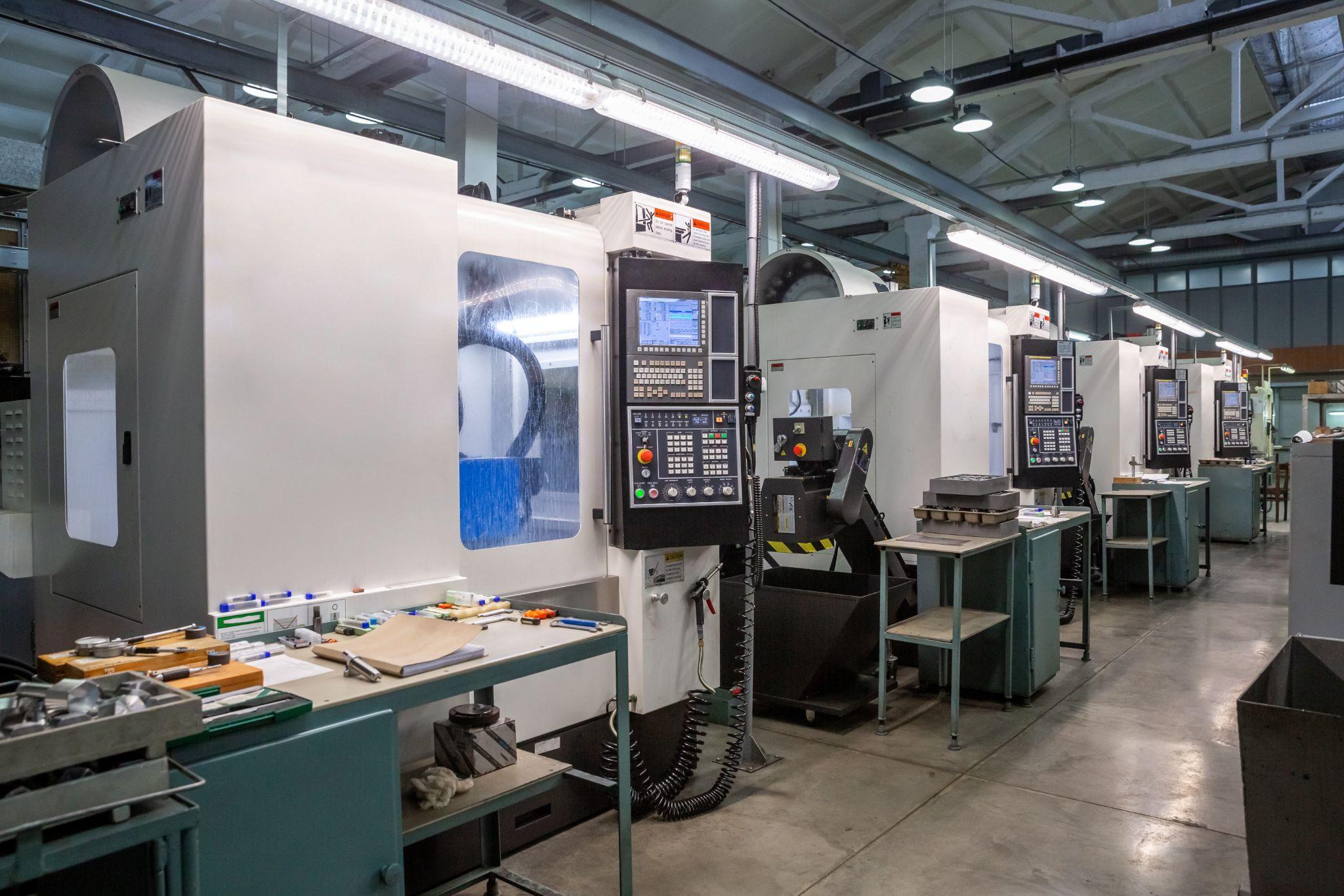
In automated production lines and smart factories, mechanisms to guarantee seating without relying on manual fine adjustment become even more important.
In robot handling and palletized automatic machining, if the workpiece is not set correctly at each step, subsequent machining will immediately produce defects.
For this reason, systems that use seating sensors or probes to verify setup—and stop the machine and trigger an alarm in case of incorrect installation—are essential.
This automatic feedback loop—“verify seating → stop on abnormality”—enables the quality assurance concept of preventing defects within the process and not passing them to downstream steps (jidoka/automatic stop).
A concrete example is a sensor used on CNC lathes to confirm contact (seating) between the chuck’s inner surface and the workpiece end face when setting the workpiece in the chuck.
Machine tool builders and sensor manufacturers offer seating confirmation switches integrated into chucks as well as the aforementioned air gap sensors, allowing continuous monitoring of proper seating even during unattended operation.
In high-precision machining lines, there is strong demand for “seating verification accuracy of ±10 µm,” and advanced factories may detect even 10 µm of lift with sensors, immediately stop machining, and alert operators.
Smart factories also integrate and manage sensor and machine information over networks. Seating-related data (e.g., “how many seating failures occurred,” “which fixtures have more,” “how often sensors are triggered,” etc.) is accumulated and used for quality improvement and preventive maintenance.
For example, if data shows repeated seating failures with a specific fixture, it can lead to countermeasures such as redesigning the fixture or adding a cleaning step.
Looking ahead, more advanced autonomous systems are becoming feasible, where AI detects early signs of abnormalities in real time from vision or acoustic sensors and makes automatic compensation or stop decisions without human intervention.
Therefore, the more automation advances, the more important it becomes for the machine itself to confirm that proper seating has been achieved.
Checks that once relied on craftsmen’s intuition and visual inspection are increasingly handled by sensors and data analysis in smart factories.
Ensuring reliable seating is key to maintaining product quality in unmanned lines and preventing issues such as production stoppages and tool breakage.
Seating Considerations in Design and Process Planning
Seating issues should be considered not only as shop-floor countermeasures but also from the product design and process design stages.
Keeping the following points in mind when defining the workpiece geometry and machining process makes it easier to achieve stable seating and ensure quality on the shop floor.
Product Design with Datums and Clamping Points in Mind
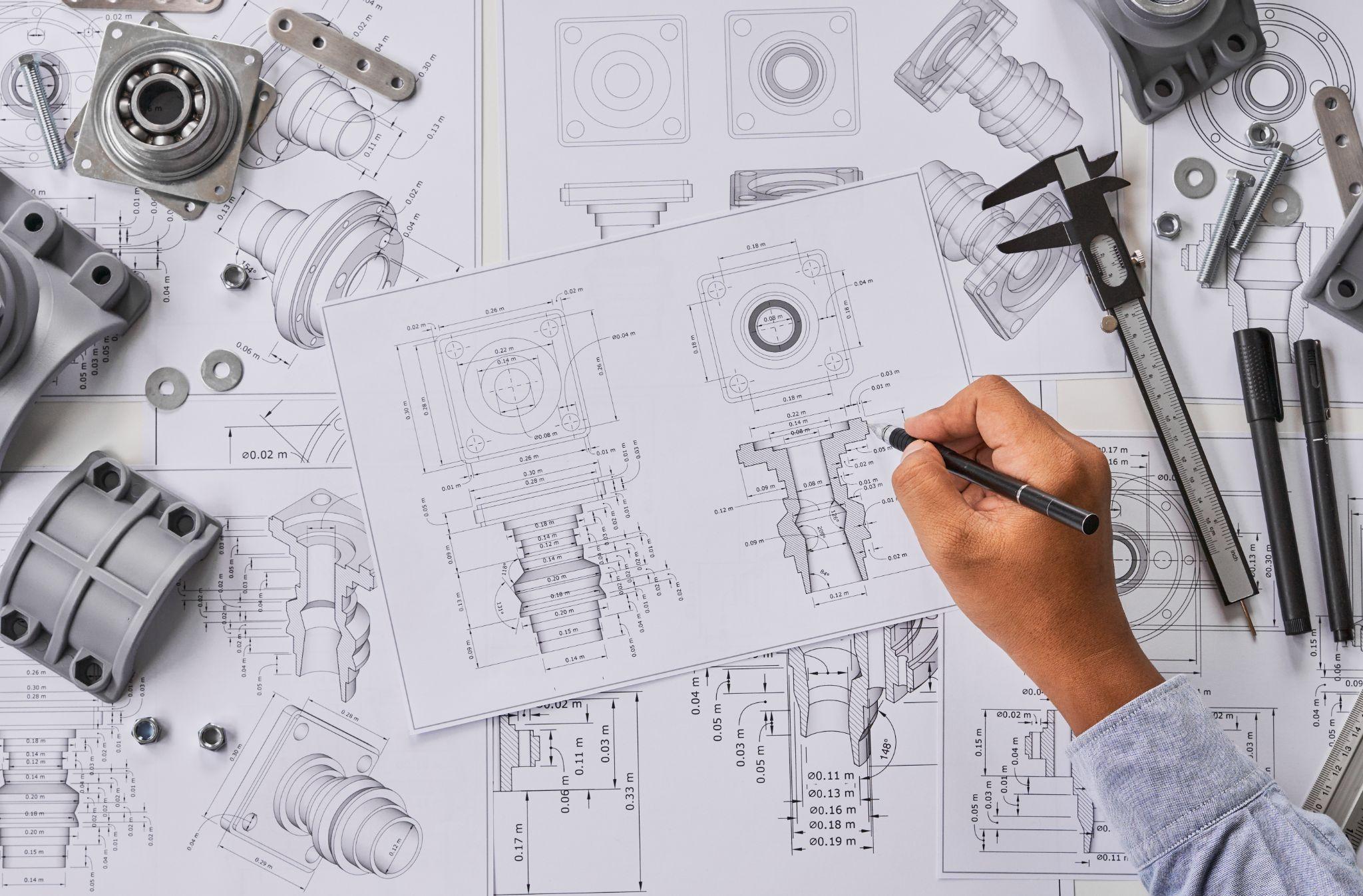
During product design, it is important to anticipate datums and clamping positions for machining. Designing one side as a large flat surface allows stable seating using that surface as a datum, and adding bosses or holes that can be gripped by a fixture enables the use of locating pins.
If the designer decides the geometry without considering where fixtures can grip (clamping allowance), the shop floor may require forced clamping or special fixtures, increasing the risk of poor seating and deformation.
As part of DFM (Design for Manufacturing), develop the habit of evaluating whether the geometry is easy to seat.
Especially for thin plates or unstable shapes that easily deflect during transfer and clamping, it can be effective to add ribs or include sacrificial material that is easy to support with a fixture and remove after machining.
Ensuring Process Stability and Repeatability
In process planning, the goal is to create a setup method that allows the workpiece to be mounted the same way every time.
One possible approach is to machine clear reference holes or datum surfaces in the first operation, then use them as locating references in subsequent operations.
In multi-step machining, changing the seating references between steps can introduce cumulative errors. Keep references consistent whenever possible, or if a reference change is necessary, insert a measurement/compensation step to reduce variation in later operations.
When re-mounting on the machine tool, it is often beneficial to use precision fixtures or pallet systems (high-repeatability reference locating mechanisms) and apply compensation values measured offline to cancel setup errors.
Impact on Fixture Design and Practical Shop-Floor Techniques
Fixture designers use many creative techniques to stabilize workpiece seating, but depending on the product geometry, secure workholding can still be difficult.
From a designer’s perspective, imagine “how will this be clamped on the shop floor?” and confirm that the geometry and tolerances are not excessively difficult to clamp.
If the material thickness at clamping points is too thin, it may deform during tightening; if all surfaces are curved and no datum can be established, dedicated fixtures may become large and complex, increasing cost.
Simpler machining fixtures are generally better, and if fixture simplification is possible through product design, it ultimately improves mass-production capability and stability.
On the shop floor, manual techniques are also used to stabilize seating, such as inserting parallels or shims, or lightly tapping with a plastic hammer during clamping to improve contact.
However, these methods depend heavily on operator skill, so it is ideal to implement poka-yoke-style measures to ensure seating as much as possible in the design and fixture stages.
High-precision seating confirmation of workpiece and jig
- Air Gap Sensor -
You can check not only "presence/absence" but also "adhesion (gap)" at the same time with a repeatability of ±0.5 μm.
Click here ›Practical Advice from a Product Designer’s Perspective
Below is a set of practical seating-related tips that are useful on the shop floor, summarized from the standpoint of a product design engineer.
Consider Manufacturing Early
At the design stage, picture the actual machining environment.
Even simply defining geometry and tolerances while imagining “Which surface will be the datum?” and “Where will it be gripped and clamped?” can make a meaningful difference in downstream stability.
By conducting DFM reviews with manufacturing—receiving feedback such as “seating may be unstable with this geometry” or “fixture support is needed here”—you can prevent major problems through design changes.
Communicate with the Shop Floor

It is also important to gather feedback from technicians and skilled workers who are actually responsible for machining.
Real comments like “this part is always hard to seat in the fixture” or “it deflects slightly when clamped, so we have to improvise” provide valuable hints for design improvement.
Designers should not rely only on desk-based studies—visit the factory and observe fixtures and machining in action. The importance of seating is best understood by seeing the real thing.
Feeding shop-floor insights back into the next product design will lead to designs that are easier to manufacture and deliver higher quality.
Common Seating Issues and Countermeasures—Based on Shop Experience
Defects and issues related to workpiece seating are problems that many people have experienced. Even today, problems caused by incomplete seating remain difficult to eliminate entirely, and companies implement a wide range of countermeasures.
Below, we describe these issues and example countermeasures based on shop-floor experience.
Below, we describe these issues and example countermeasures based on shop-floor experience.
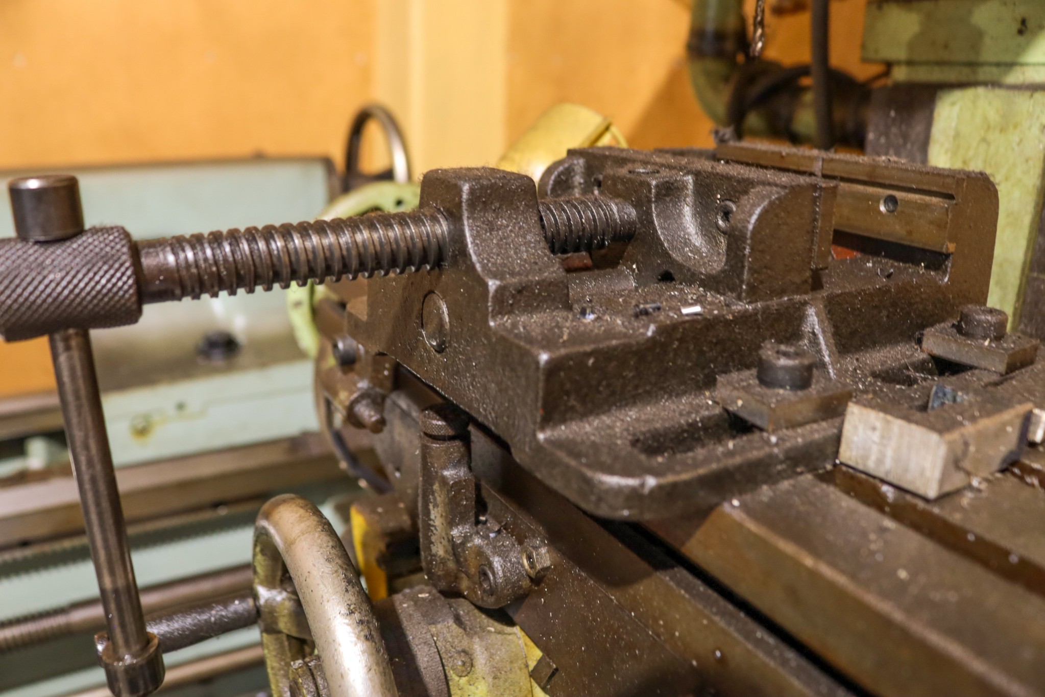
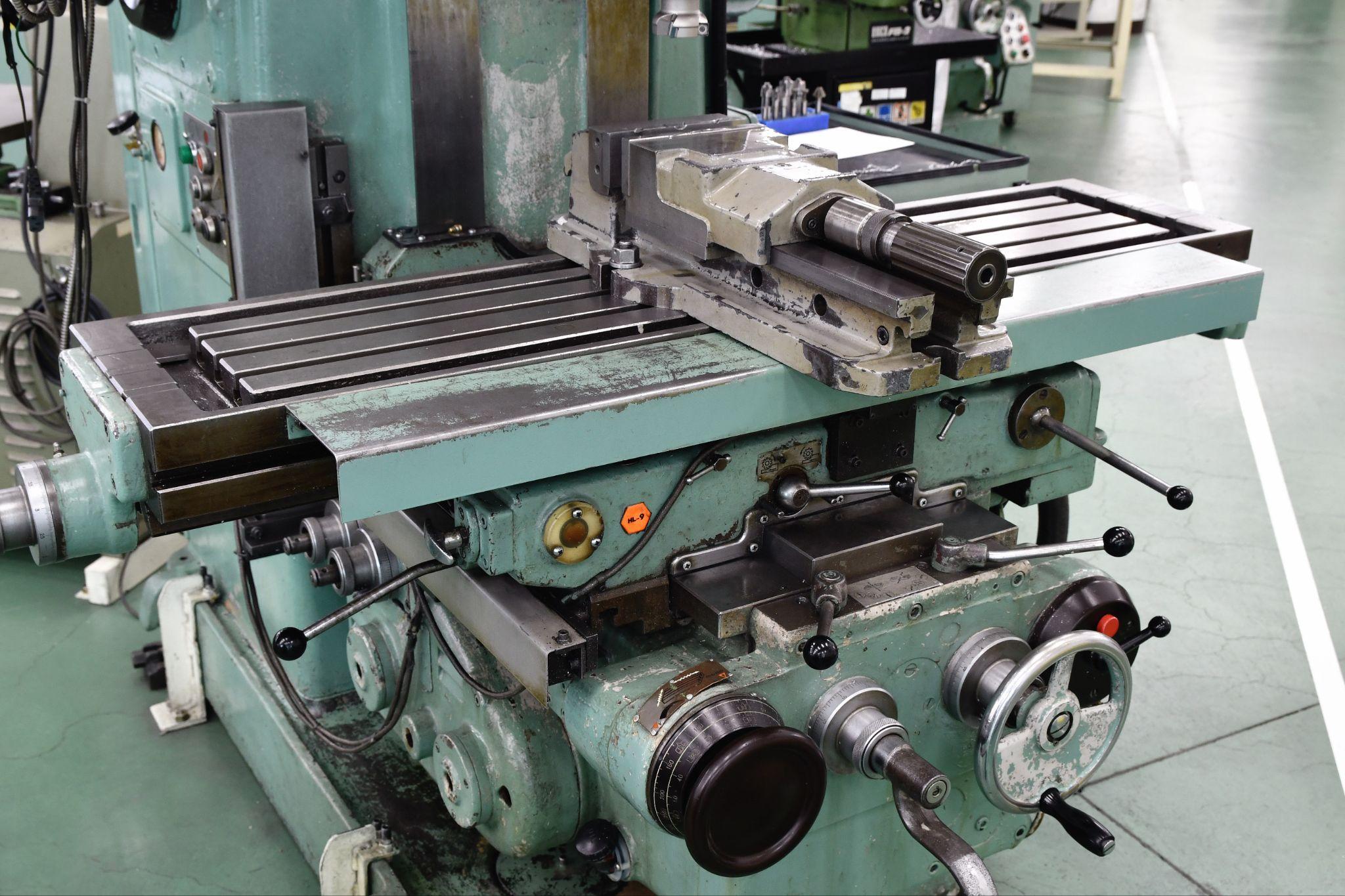
A vise grips a workpiece using a stationary jaw and a movable jaw. Seating issues can occur when the movable jaw develops play due to excessive impact or aging, causing an upward force to act on the movable jaw during tightening.
As mentioned earlier, some vises designed for precision machining incorporate an angular-lock mechanism that applies a downward holding force when gripping the workpiece, helping it seat against the vise base.
Even with such a vise, if workpiece lift (incomplete seating) still occurs, the quickest path to a solution may be to suspect the workpiece itself.
Workpiece lift can also occur when the clamped workpiece lacks proper squareness or parallelism.
As a cause of incomplete seating and a starting point for countermeasures, before questioning the workholding device or machine accuracy, first revisit machining fundamentals: “Are we using a machining method and procedure that can achieve squareness and parallelism?”
If a six-sided workpiece has been machined using methods and steps that achieve squareness and parallelism, its seating will be stable; when clamped in a vise, lightly tapping it from above with a plastic hammer will leave the parallel blocks immobile.
If you strike it too hard, rebound forces can occur and seating may become unstable instead.
When Machining Warped Plates, Clamp with the Convex Side Down
When machining plate stock on a machining center, it is not uncommon for the material to be warped before processing.
When machining such workpieces, be sure to clamp them with the convex side down (toward the table) and then perform machining.
If the convex side faces up, the center of the workpiece lifts and seating becomes unstable, which can lead to surface quality issues caused by deflection or chatter during machining.
Clamping with the convex side down improves seating between the workpiece and the table, which can mitigate issues that often occur near the center—such as chatter during side milling with an end mill, or inconsistent counterbore depth due to deflection.
What Are Metrol’s High-Precision Positioning Sensors?
In “seating verification” and “positioning” processes that strongly influence machining accuracy, detection technology that does not miss even a few microns of error is required.
Metrol offers a diverse lineup, including contact switches with repeatability up to 0.5 µm and air micro sensors that non-contactly detect lift under 10 µm. Here, we introduce Metrol’s representative positioning sensors that directly address shop-floor challenges.
Here, we introduce Metrol’s representative positioning sensors that directly address shop-floor challenges.
High-Precision Positioning Touch Switches
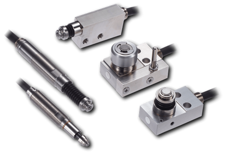
These are contact-type high-precision switches used for positioning and workpiece presence detection in machine tools, robots, and jigs. They achieve an extremely high repeatability of up to 0.5 µm and feature IP67-rated waterproof and dustproof protection, ensuring stable operation even in harsh environments. With more than 200 standard models available, they offer a wide range of variations, including designs for confined spaces, high-temperature environments, vacuum applications, and low contact force requirements.
Tool Setter (Tool Length Measurement Sensor)
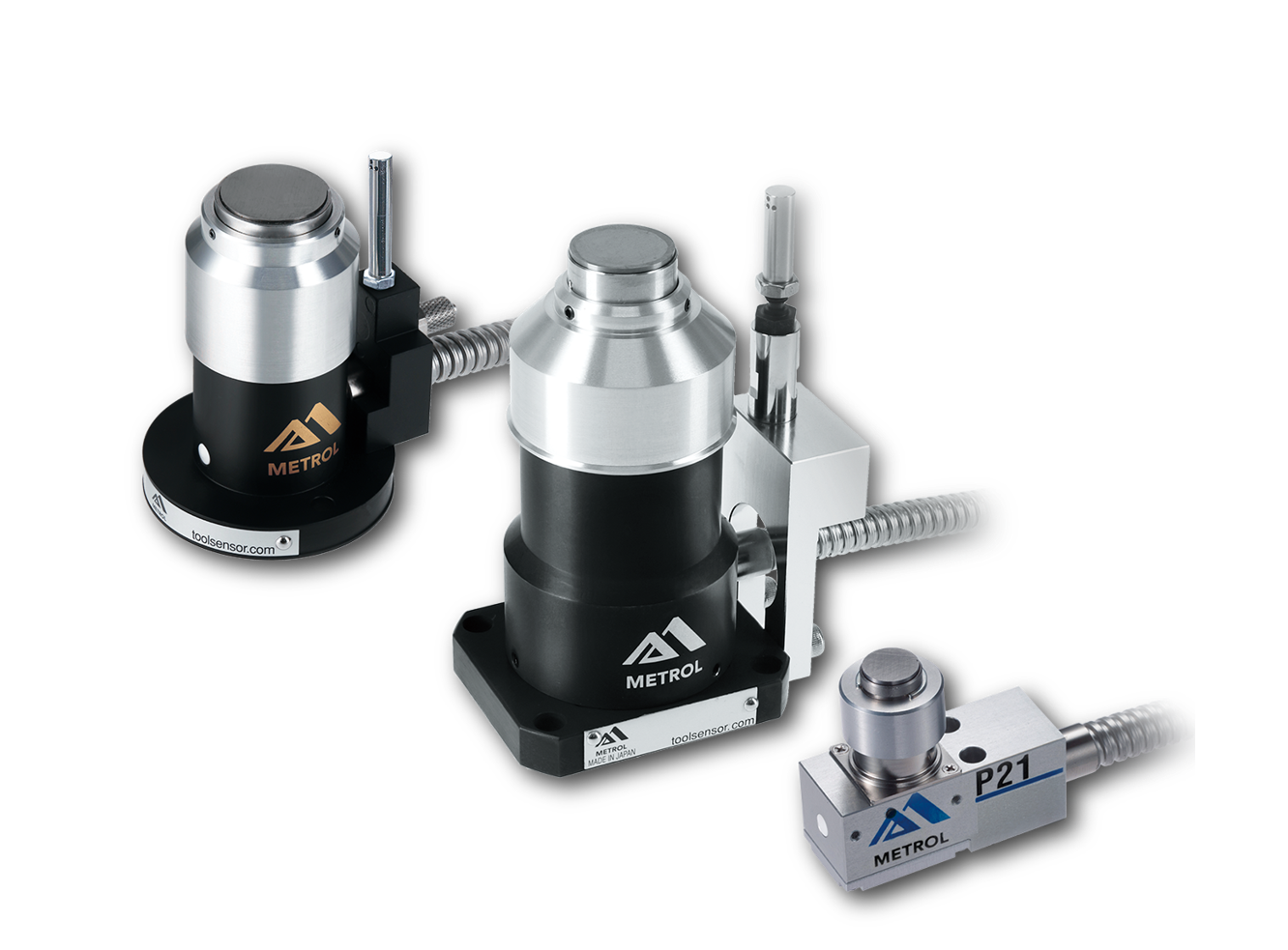
This is a contact-type sensor installed on CNC machine tools and industrial robots for tool length measurement, reference position setting, and tool breakage detection. By automatically measuring and compensating for tool length, wear, and thermal displacement inside the machine, it helps prevent machining defects and significantly reduces setup time. It is one of Metrol’s best-selling products, with a proven track record of more than 500,000 units shipped in 74 countries worldwide.
Touch Probe (On-Machine Measurement Probe)
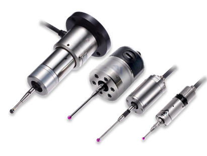
This is a contact-type probe for in-machine measurement, installed on machine tools and robots to automatically perform workpiece positioning (centering) before machining and dimensional measurement after machining. With a repeatability of 1 µm, it automates workpiece referencing and dimensional inspection, replacing skilled manual operations to reduce setup time and help prevent machining defects. Both wired and wireless models are available, meeting retrofit needs for 5-axis machining centers and robotic applications.
Air Gap Sensor (Pneumatic Sensor)
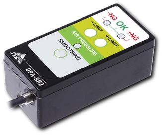
This is a non-contact sensor that uses air pressure to detect workpiece seating conditions with micron-level accuracy. It can detect gaps (“lift”) of less than 10 µm—previously difficult to measure—with a repeatability of ±0.5 µm, helping prevent machining defects and equipment downtime caused by insufficient contact between the workpiece and fixture. The sensor is used in applications such as semiconductor manufacturing processes, precision part clamping operations, and grinding wheel positioning on grinding machines, and it is a smart sensor that also supports the international standard IO-Link communication.