Milling Basics: Material Properties, Cutting Tools, and Key Points When Outsourcing Work
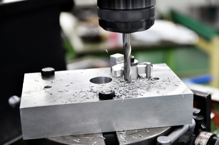
Today, machining with machining centers has become the standard in manufacturing sites, allowing even less-experienced operators to produce high-precision parts in a relatively short period of time. As a result, many people do not fully understand the basics of milling, and it is not uncommon for them to struggle when troubles occur during machining.
In this article, we clearly explain the fundamentals of milling, including cutting tools, workpiece materials, and how to troubleshoot common machining problems.
Table of Contents
Basic Knowledge of Milling
Milling is a machining method in which a high-speed rotating cutting tool is brought into contact with a workpiece. It is a type of material removal process, using tools such as face mills and end mills to cut away unnecessary material and create the desired shape.
Milling is mainly used for machining prismatic workpieces such as six-sided parts, but by selecting from various tools such as drills and side cutters, it can also produce complex features including flat surfaces, curved surfaces, slots, and holes.
Differences from Other Machining Methods (Lathe Machining)
Cutting processes can be broadly divided into two types: milling and turning. Milling uses a milling machine, while turning uses a lathe.
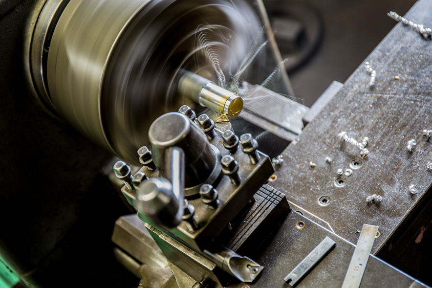
Turning is a machining method that uses a lathe, in which the workpiece is rotated at high speed while a cutting tool fixed to the tool post is pressed against it. Machining is performed along two axes: the radial direction (X-axis) and the longitudinal direction (Z-axis). For this reason, conventional lathes are mainly used to create rotationally symmetric shapes such as cylinders, hollow cylinders, cones, and threads.
In contrast, milling uses three machining axes—X (left/right), Y (front/back), and Z (up/down)—making it possible to machine more complex geometries than a lathe, including flat surfaces, slots, pockets, and three-dimensional curved surfaces.
Machine Tools and Cutting Tools Used in Milling
The appropriate selection of machine tools and cutting tools depends on the part geometry, size, and required machining accuracy.
Use the table below as a reference when selecting suitable machines and tools.
Machine Tools Used
| Machine | Advantages | Disadvantages |
|---|---|---|
Milling machine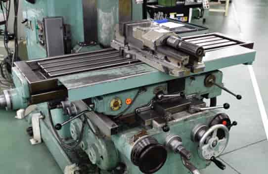 | ・Setup can be simplified. ・It is easier to respond to unexpected incidents such as tool breakage. ・Running costs are lower than those of numerically controlled equipment. | ・A certain level of operator skill is required. ・Complex geometries such as curved surfaces are difficult to machine. ・Machining accuracy varies depending on the operator’s skill level. |
NC milling machine | ・Complex geometries such as curved surfaces can be machined. ・There is less variation in machining accuracy due to individual differences or skill level. ・Machining conditions can be stored. ・A certain degree of labor saving and unattended operation is possible. | ・Programming knowledge is required. ・Not well suited to workpieces that require many different tools. |
Machining center 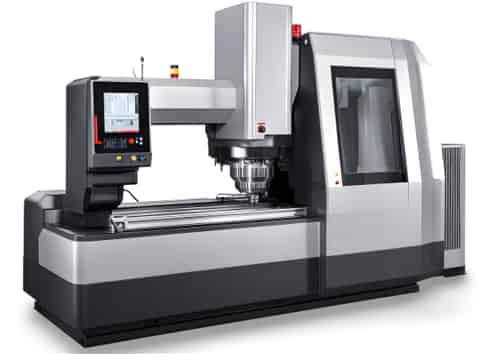 | ・It can machine curved surfaces and angled features that are difficult to produce manually, while maintaining high dimensional accuracy. ・Multiple tools can be used in a single setup. ・Even non-expert operators can perform the work, helping reduce labor costs. ・It offers relatively safe operation. ・By using robots or pallet changers, labor saving and unattended nighttime machining are possible. | ・Programming knowledge is required. ・ Setup becomes more complex. ・ Running costs are high due to lubricants, coolant, tool holders, and related items. ・The equipment itself, as well as initial and maintenance costs, is expensive. |
NC gear cutting machine | ・Because dedicated tools are used, complex coordinate calculations, programming, and setup are unnecessary. | ・In principle, it can only be used for gear machining. ・The dedicated hob tool is relatively expensive. |
Types of Cutting Tools and Machining Operations
The main tools used for machining prismatic workpieces include the following:
| Tool | Main Applications | Notes |
|---|---|---|
Face mill | Used for machining the face of a workpiece. It has a larger cutting diameter than an end mill and can machine wider surfaces. | In recent years, many products compatible with plunge cutting (helical interpolation) have also become available. |
Side cutter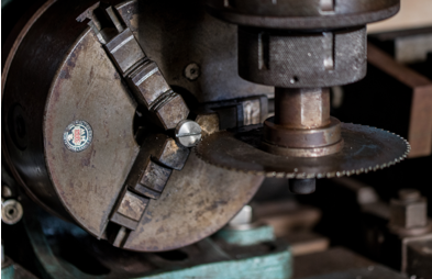 | Used for slotting workpieces. Staggered-tooth side cutters, which have alternating side cutting edges, are suitable for heavy cutting. | The difference from a metal saw is whether cutting edges are present on the side faces of the cutter. |
End mill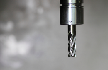 | Used for machining the sides, slots, and similar features of a workpiece. Many products are also compatible with plunge cutting and helical interpolation. | For deep holes and slotting operations where chips tend to clog, some types can supply coolant through the holder interior (through-coolant type). |
| Solid end mill | Used for side milling, slotting, plunge cutting, helical interpolation, and counterboring. Available in HSS and carbide types, and both side and bottom cutting edges can be reground. | Coated types are more expensive, but their high wear resistance makes them well suited for difficult-to-cut materials. |
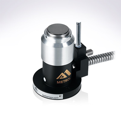
Automates originating of cutting tools
- Tool Setter -
Tool length and chips are monitored to prevent machining defects due to wear and thermal displacement
Click here ›Materials Used in Milling
Common workpiece materials used in milling include the following:
Steel Materials Such as SS400 and S45C
SS400 and S45C are commonly used materials in machining, as they are readily available and relatively inexpensive.
S45C in particular is classified as a carbon steel for machine structural use, and its hardness and mechanical properties can be improved through heat treatment.
It offers good machinability and can be machined with a wide range of tool materials, excluding tools intended for non-ferrous metals and diamond tools.
Aluminum Alloys
Aluminum alloys have good machinability and are lighter than steel materials, which is why they are used in aircraft components. They are also suitable for mass production through casting and extrusion.
They also offer higher corrosion resistance than steel and are non-magnetic, making them suitable for environments sensitive to magnetic influence, as well as locations exposed to fresh water, seawater, or low temperatures.
Because aluminum has a low melting point and tends to adhere to cutting edges, wet machining is generally preferred, and high-speed cutting with carbide tools is most suitable.
Copper and Brass
Copper has good machinability, but because it is ductile and has a low melting temperature, it tends to form a built-up edge, where material adheres to the cutting edge.
For cutting copper, oil-based coolant and sharp tools with a large rake angle are recommended, and high-speed machining is suitable.
Brass has good machinability and is a metal that is easy to process by bending, welding, polishing, and similar methods.
Its main applications include machine parts, terminals for electronic devices, wiring hardware, and brass instruments such as trumpets, where its attractive appearance is also valued.
Because brass has high ductility, burrs tend to form during machining and the tool tends to bite in more aggressively, so tools with a smaller rake angle are recommended.
Resins
Depending on their melting point, resins are classified into plastics, engineering plastics, and super engineering plastics. Other materials suitable for machining include ABS, polyethylene, PET, acrylic, and polycarbonate.
Because resins have low thermal conductivity and heat generated during machining can easily affect dimensional accuracy, sharp tools with a large rake angle are recommended.
Machining Difficult-to-Cut Materials
Difficult-to-cut materials is a general term for materials that are more difficult to machine than ordinary metals. While they offer excellent properties such as high strength, heat resistance, and corrosion resistance, they also present challenges in machining efficiency.
Stainless Steels Such as SUS303 and SUS304
SUS303 and SUS304 have excellent heat resistance and corrosion resistance, so they are mainly used for machine parts and housings intended for harsh environments.
Because stainless steels have high strength and hardness, tool life tends to be shorter and machining time longer, making stainless steel parts more expensive than ordinary steel parts. Stainless steel also has low thermal conductivity and tends to work harden, so wet machining with sufficient coolant is more suitable than dry cutting.
Titanium
Titanium is lighter than steel and offers excellent strength, heat resistance, and corrosion resistance, but it is difficult to machine and the raw material itself is expensive, so machined titanium products are generally more costly than steel products.
Titanium alloys have tensile strength about twice that of steel, and because of their low thermal conductivity, cutting tools are more likely to be damaged.
They are also prone to chatter, and the chips generated during cutting can ignite easily, so carbide tools should be used, cutting speed should be reduced, and chips should be removed frequently during machining.
Inconel
Inconel, which is classified as a heat-resistant alloy, is used for machine parts operating under high-temperature and high-pressure conditions, including aircraft and rocket engines, steam turbines in power plants, and exhaust systems for cars and motorcycles.
Because cutting edges wear more quickly than when machining stainless steel, which is also a difficult-to-cut material, coated carbide tools with excellent wear resistance are recommended.
It is also effective to use cutters with a high helix angle, a positive rake angle, or a larger number of flutes to distribute the load on the cutting edge.
Troubleshooting in Milling
Below is a summary of common milling troubles, along with their main causes and countermeasures.
| Trouble | Main Cause | Countermeasure |
|---|---|---|
| Chatter | Insufficient workpiece holding rigidity | • Review the workpiece holding method. • Reduce the depth of cut to decrease cutting resistance. • Select tools with a smaller corner R or parallel land. Use non-coated tools. |
| Workpiece weak in the axial direction | • Use a square cutter with a positive chip breaker. • Select a tool with a smaller corner R. • Reduce the depth of cut. • Check tool wear frequently. • Improve tool holder runout and the holding method. | |
| Excessive tool overhang | • Minimize tool overhang. • Use a variable-pitch cutter. • Increase feed per tooth. • Use up-cut milling during finishing. • Use carbide tools. • Select a 45° lead angle, a large corner R, or round inserts. | |
| Low-rigidity spindle / unstable table feed | • Select a smaller tool diameter. • Try up-cut milling. • Use a positive-rake or light-cutting cutter. • Check spindle and table-feed deflection. | |
| Cutting conditions | • Reduce the cutting speed. • Increase the feed rate. • Select an appropriate depth of cut. | |
| Chip clogging | Insert corner damage, edge chipping or breakage, chip recutting | • Supply cutting oil or compressed air with sufficient pressure and proper directionality. • Increase the number of machining passes. • Try up-cut milling for deep slots. • Use a coarse-pitch cutter, a carbide end mill, or a high-helix end mill. |
| Chip recutting | Cutting edge damage, tool life, chip clogging | • Use compressed air or ensure sufficient discharge pressure. • Supply cutting oil with proper directionality. • Select tools and machines with through-coolant capability. • Reduce the feed rate. • Change the cutter position or tool path, and increase the number of passes. |
| Surface roughness | Excessive feed per revolution | • Check spindle runout and the cutter mounting surface. • Reduce the feed to 70% of the insert’s parallel land width. • Use wiper inserts during finishing. |
| Built-up edge formation | • Increase the cutting speed. • Try dry machining. • Select tools with a large rake angle or positive chip breakers. • Use a cermet grade. | |
| Workpiece deformation | • Reduce the feed rate. • Adjust the cutter position to make the chips thinner at cutter exit. • Use sharp inserts or light-cutting breakers. • Check flank wear on the tool. | |
| Burr formation | Workpiece material properties, notch wear | • Use inserts with a larger corner R to reduce the lead angle. • Keep the depth of cut smaller than the corner R. • Review the cutter path. |
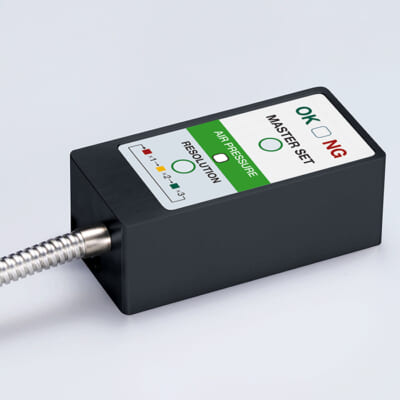
High-precision seating confirmation of workpiece and jig
- Air Gap Sensor -
You can check not only "presence/absence" but also "adhesion (gap)" at the same time with a repeatability of ±0.5 μm.
Click here ›Key Points When Outsourcing Milling
When outsourcing milling work, clearly communicate key requirements such as the shape and accuracy of the part, the material to be used, the quantity, and the delivery date. Among these, the following points are particularly important.
Key Points in Drawing Preparation
First, be sure to clearly specify all basic dimensions such as length, width, and height, as well as dimensional tolerances, geometric tolerances, and surface roughness requirements (such as Ra values).
As a cost-reduction measure, it is effective to clearly indicate the surfaces that require especially high precision on the drawing, while moderately relaxing tolerance and surface roughness requirements for surfaces that do not significantly affect product performance.
Tolerances and Finishing
In milling, medium-grade dimensional tolerances can generally be achieved. Surface roughness is also often specified using target values such as Ra 1.6 or Ra 3.2. Please note that specifying tighter-than-necessary tolerances or surface finish requirements can significantly increase machining costs.
Precautions Regarding Machined Areas and Shapes
In some cases, machining may not be possible because of interference caused by a small specified corner radius and the end mill geometry. It is important to review in advance whether the specified R dimension is truly necessary and to discuss this with the machining supplier.
In addition, when machining deep holes or pocket features, tool deflection and machining vibration tend to increase, which can lead to lower machining accuracy and higher costs. In such cases, consider dividing the part into multiple components or modifying dimensions to make machining easier wherever possible.
Metrol Sensors That Contribute to Milling Automation
High-Precision Positioning Touch Switches
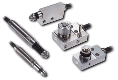
Metrol positioning touch switches are high-precision touch sensors that do not require an amplifier.
In milling applications, they can be used for X- and Y-axis positioning, checking workpiece presence, seating, and dimensions, as well as tool length measurement and breakage detection for small-diameter tools, and robot positioning.
Tool Setter
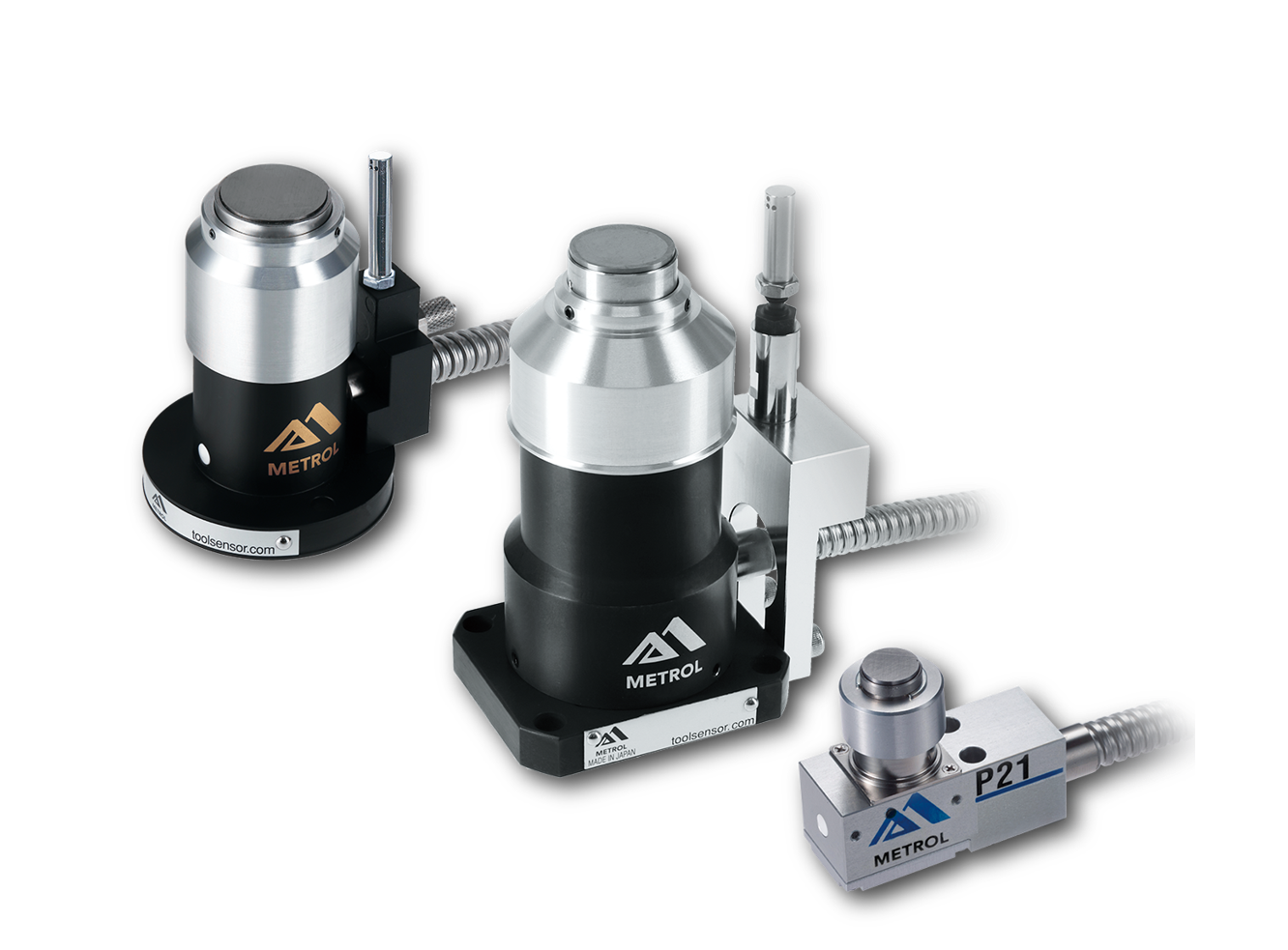
Metrol tool setters are high-precision touch sensors used for positioning tools and nozzles on CNC machine tools and industrial robots.
They can be used for tool length measurement, wear and breakage detection, and thermal displacement detection, helping prevent machining defects and collisions caused by tool wear or breakage.
Touch Probe
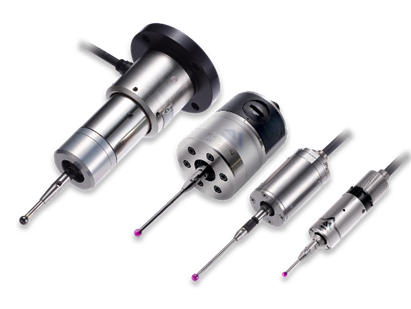
Touch probes are contact-type sensors for in-line measurement, mainly used on CNC machine tools and industrial robots.
Metrol touch probes can automate tasks such as pre-machining workpiece origin measurement and post-machining dimensional inspection, helping eliminate operator dependency, reduce setup time, improve cycle time, and prevent machining defects.
Air Gap Sensor
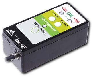
Metrol air micro sensors are high-precision air sensors capable of verifying proper workpiece seating.
They can be used to detect micron-level gaps caused by chip entrapment during workpiece clamping, inspect the inner diameter of workpieces, and align rotating grinding wheels on CNC grinders. They also support the IO-Link communication standard, enabling reduced wiring.
Related Articles
CNC automatic lathes, what you ABSOLUTELY need to know for MAXIMUM use?
This article explains the Cincom series of CNC automatic lathes from Citizen Machinery, which Metrol also uses.
- We want to advance NC implementation in our machining department.
- We want to eliminate machine troubles and minor stoppages to improve operating rates.
- We want to consolidate processes and streamline pre- and post-processes such as inspection.
This article is recommended for those with these goals in mind.