What Is a Fiber-Optic Sensor? Fundamentals, Key Types, and Practical Points for Real-World Use
Fiber-optic sensors are a specialized sensing technology that enables stable measurement even in harsh environments such as strong electromagnetic noise and high temperatures. Using optical fibers, they detect temperature, strain, pressure, and other physical quantities as changes in optical signals, making it possible to measure in extreme conditions where conventional electrical sensors struggle.
In manufacturing settings, they demonstrate particular strength in precision measurement under intense electromagnetic noise—around high-frequency induction heating furnaces and plasma cutting equipment, for example.
This article explains practical, job-relevant knowledge—from basic principles and major sensor types to concrete use cases in machine tools and metalworking, criteria for deciding whether to adopt them, and key points for real-world operation.
Table of Contents
What is a fiber-optic sensor?
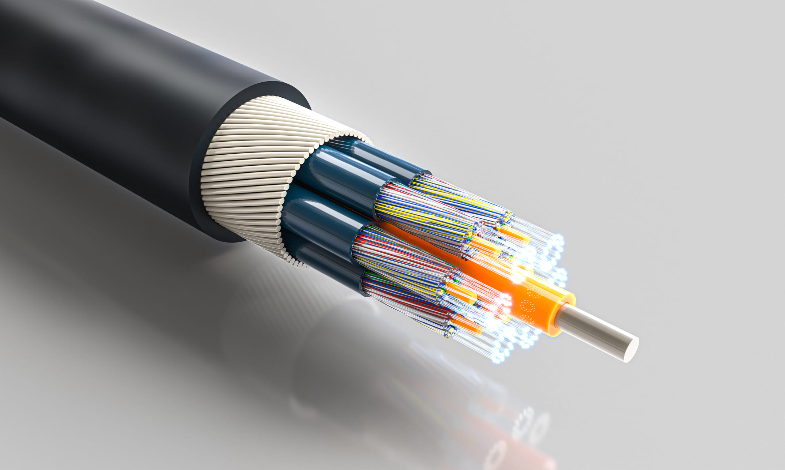
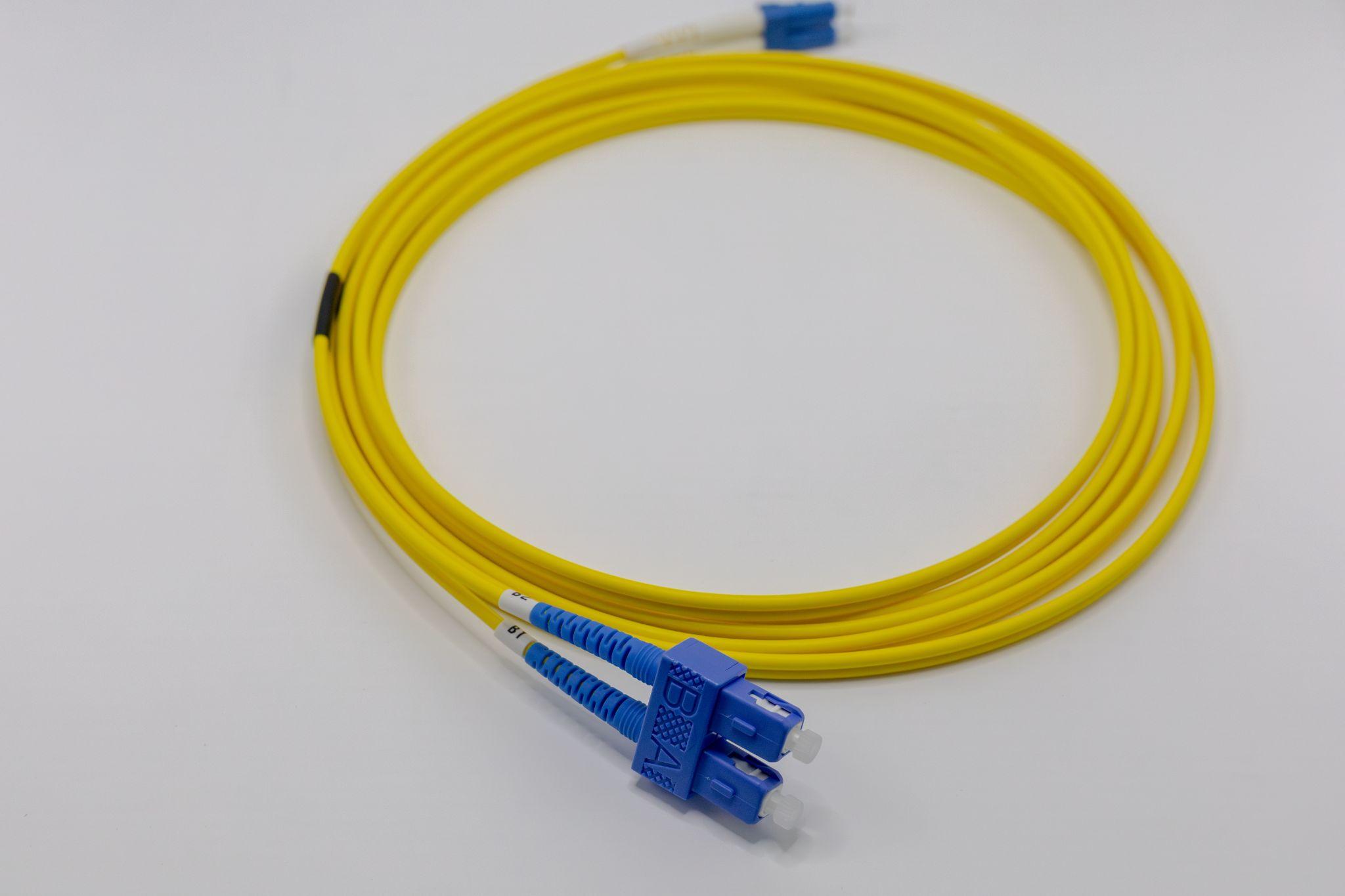
A fiber-optic sensor (also called an optical fiber sensor) is a technology that uses the same thin optical fibers employed for communications as the sensing element itself, measuring various physical quantities—such as temperature, strain, and pressure—as changes in optical signals.
It leverages the fact that characteristics of light—wavelength, intensity, phase, polarization state, and more—change depending on the surrounding environment, enabling measurement by sending light into an optical fiber from a remote location.
Because optical fibers are non-conductive media made of glass or plastic, they are electromagnetically passive. This provides high safety and draws attention as a sensing method suitable for harsh environments.
Thanks to these characteristics, fiber-optic sensors are being adopted across a wide range of fields, including aerospace, civil-structure monitoring, medical and biosensing, and environmental monitoring.
Basic structure and operating principles of fiber-optic sensors
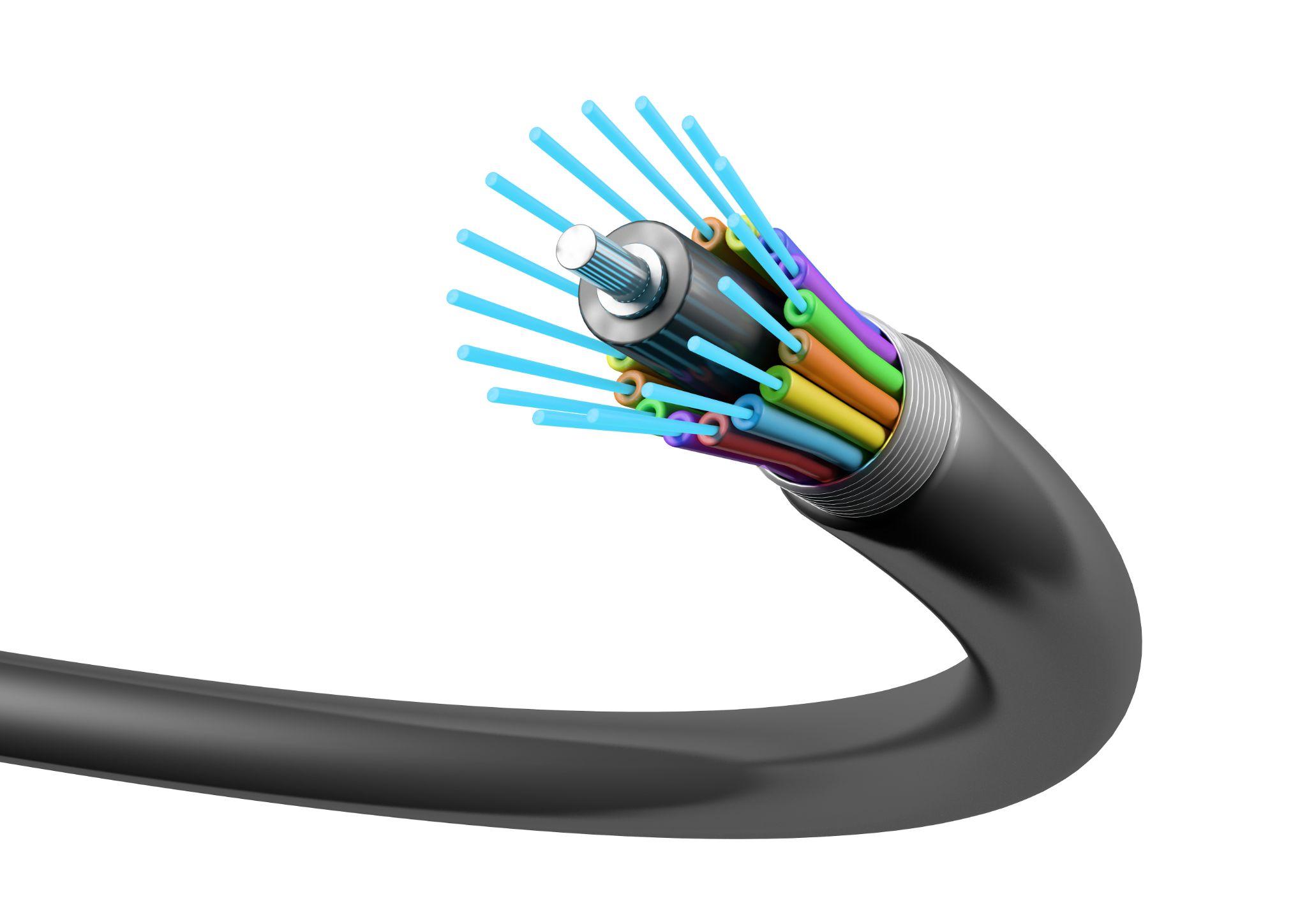
An optical fiber is an extremely thin dielectric (electrically insulating) waveguide with a two-layer structure consisting of a core and cladding. When light is guided through the fiber, the refractive-index difference between the core and cladding confines the light within the core and allows it to propagate.
When the optical fiber itself acts as the sensing element, environmental changes (such as temperature change or strain) cause minute expansion/contraction or bending of the fiber, which in turn changes properties of the light traveling inside it (such as intensity or phase).
For example, if constant light is injected into an optical fiber and the fiber thermally expands as temperature rises, the returned optical signal changes in accordance with the length change. By analyzing this change with a photodetector, you can determine the amount of temperature change.
Many fiber-optic sensors operate by directly converting physical changes in the environment into changes in optical signals, and then measuring by analyzing those optical signals.
Fiber-optic sensor configurations broadly fall into internal and external types. In the internal type, the optical fiber itself is the sensing region, and the light propagating within the fiber is directly modulated.
Without adding a separate sensor element, it detects changes in the intensity, phase, wavelength, and other properties of the light traveling in the fiber as they vary with the surrounding environment. In this approach, light can be transmitted without leaking outside the fiber, and the fiber plays a dual role as both sensor and transmission path—an advantage for multipoint measurement and long-distance monitoring.
In the external type, the optical fiber primarily serves as a medium to carry light, while a miniature sensor head placed at the fiber tip or along the fiber (e.g., a Fabry–Pérot interferometer) performs optical modulation according to environmental changes.
This allows the sensor head to be deployed into extreme environments that are normally difficult to access (such as inside an engine), with the optical fiber acting as the delivery and transmission path.
However, with external-type systems, integration can be challenging—for example, when combining with conventional electrical sensors, you may need to convert outputs into optical signals.
Fiber-optic sensors can be classified into several methods based on operating principles. Representative types include intensity-modulated, phase-modulated, wavelength-modulated, and distributed sensors.
Intensity modulation is the most basic method, based on changes in input/output optical intensity, and can be implemented with a simple configuration that connects a light source and a photodetector to the fiber. Phase modulation uses interferometry to detect changes in optical phase with high sensitivity. A representative wavelength-modulated approach is the Fiber Bragg Grating (FBG) sensor, which measures strain or temperature as changes in optical wavelength (spectrum).
Distributed sensing analyzes scattered light along the entire fiber length, enabling continuous detection of physical-quantity changes by location. There are also polarization-based approaches that use changes in polarization state, applying the phenomenon in which polarization changes due to birefringence effects within the optical fiber. The next section explains the most important types in more detail.
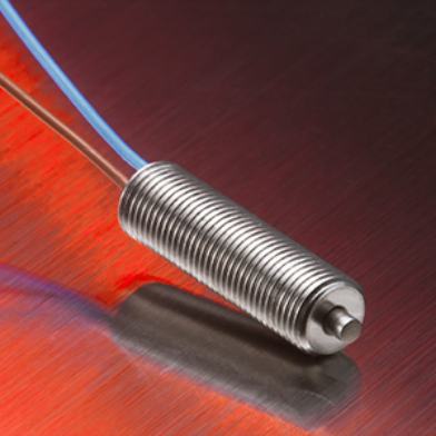
High Precision Positioning
- MT-Touch Switches-
0.5 μm repeatability without amplifier IP67, highly resistant to adverse environments
Click here ›Main types of fiber-optic sensors
Below is an overview of the main classifications based on sensing principles.
Intensity-modulated sensors
This is the simplest type of fiber-optic sensor, detecting changes in optical intensity (power). For example, it can use phenomena such as microbend loss—where light slightly leaks and attenuates when the fiber bends—to measure strain and similar quantities as optical attenuation.
It offers a simple structure and low cost, but it is susceptible to unwanted intensity fluctuations—such as light-source output drift and loss changes at connection points—so a reference path may be required to compensate for error factors.
Phase-modulated (interferometric) sensors
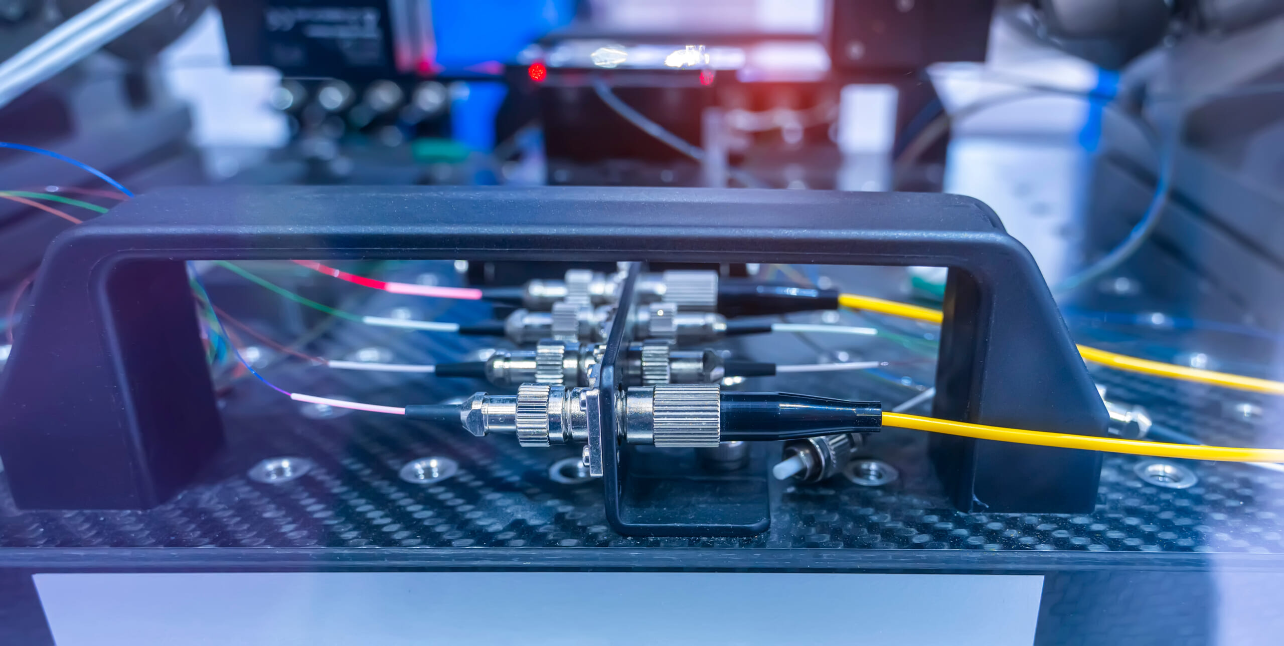
This approach detects changes in optical phase with high sensitivity and mainly uses optical interferometers. Representative examples include the Mach–Zehnder interferometer, Sagnac interferometer, Michelson interferometer, and Fabry–Pérot interferometer.
The basic principle is that environmental factors change the phase difference between reference light and measurement light; the resulting interference fringes are used to read minute phase variations. While it can achieve extremely high sensitivity and resolution, the optical system tends to be complex and costly.
For example, optical gyros (fiber-optic gyroscopes) that use fiber interferometers have been commercialized as high-precision inertial navigation devices for aircraft and satellites.
Wavelength-modulated sensors (FBG sensors)
Wavelength-modulated sensors use a special diffraction grating called an FBG (Fiber Bragg Grating) formed inside an optical fiber, reflecting only a specific wavelength of light for sensing.
An FBG is a structure in which fine periodic refractive-index modulation (a grating) is written into the fiber core—via methods such as UV interferometry—selectively reflecting only light at a specific wavelength.
When environmental changes (such as strain or temperature) alter the grating spacing or core refractive index, the reflected Bragg wavelength shifts slightly. By measuring this wavelength shift, you can detect changes in strain or temperature with high accuracy.
Because the signal is encoded as wavelength (an absolute value), FBG sensors are less affected by light-source power fluctuations and therefore offer high stability.
If different grating pitches are written for each sensor, they reflect different wavelengths, making it easy to place many FBG sensors in series along a single optical fiber for simultaneous multipoint measurement (wavelength-division multiplexing).
For this reason, FBG sensors are currently the most widely used sensing elements, offering versatility from single-point measurement to multipoint measurement across dozens of points.
In recent years, advances in fiber-laser-based FBG fabrication have accelerated research into operating FBG sensors in extremely high-temperature environments. For example, Type II FBGs fabricated using femtosecond lasers have been reported to operate stably over long periods at temperatures of 1000°C.
Distributed sensors
Distributed fiber-optic sensors enable a single optical fiber to function as a spatially continuous sensor. Light propagating through the fiber constantly generates weak scattered light such as Rayleigh scattering, Raman scattering, and Brillouin scattering.
By analyzing the intensity and frequency shift of these scattered components, you can measure environmental changes experienced at each position along the fiber.
A typical method is OTDR (Optical Time Domain Reflectometry), which injects pulse light into the fiber, identifies the scattering location from the time delay until backscattered light returns, and calculates temperature or strain from changes in scattering intensity.
Systems using Brillouin scattering can continuously measure strain and temperature over tens of kilometers, making them useful for remote monitoring of large-scale structures.
Because the optical fiber itself becomes a long, continuous sensor, distributed sensing is expected to be applied to wide-area infrastructure monitoring—such as bridges and pipelines—and to disaster-prevention monitoring (landslide detection and seismic-motion monitoring).
Applications of fiber-optic sensors
Leveraging the characteristics described above, fiber-optic sensors are being applied across a wide variety of fields. Here, we introduce major examples by application area.
Medical and biosensing
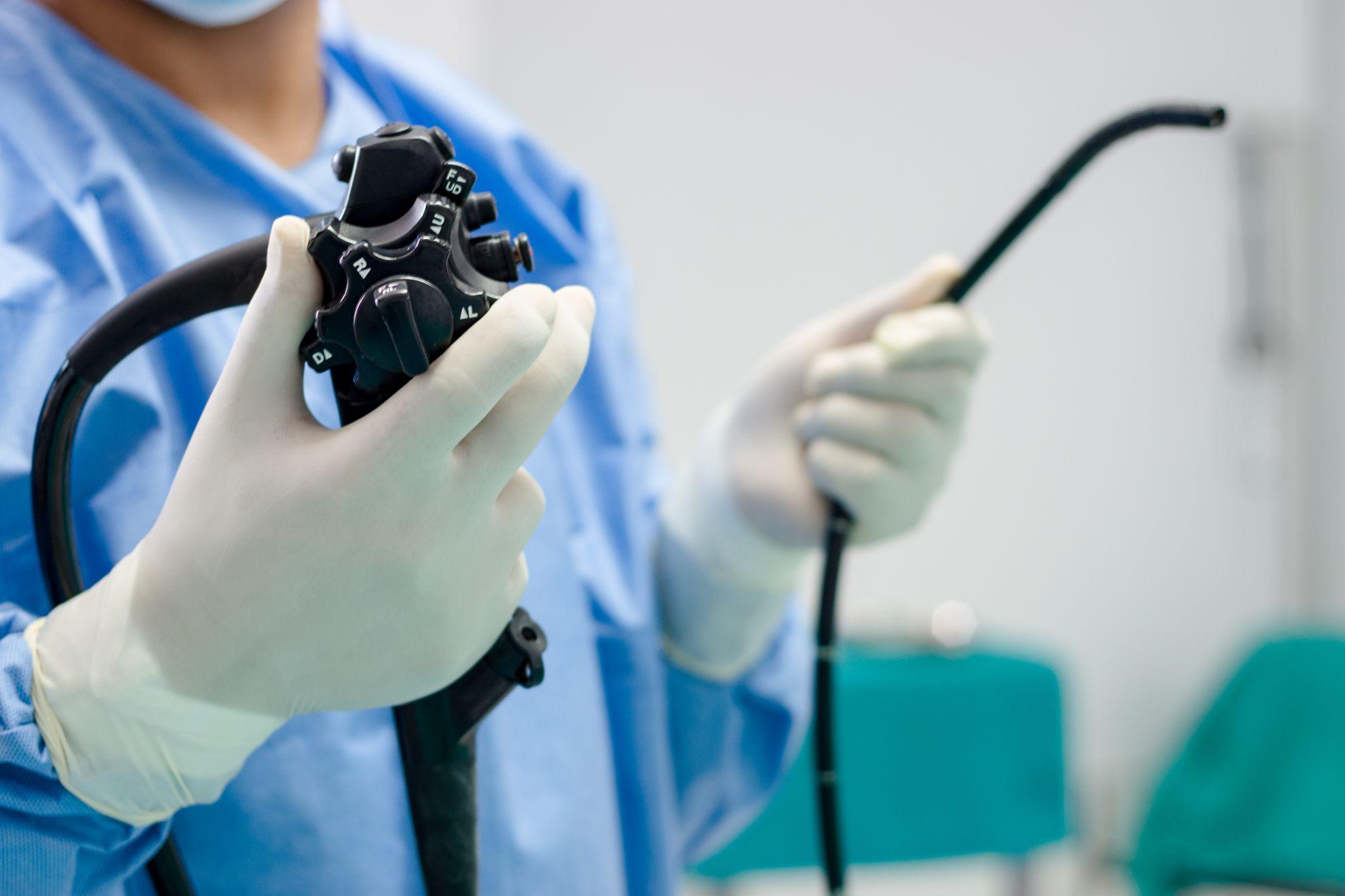
Fiber-optic sensors also hold significant potential in the medical field. Taking advantage of thin, flexible optical fibers that can be inserted into the body, they are applied to pressure sensors integrated into catheter tips and to endoscopic methods for measuring internal temperature and strain.
For example, heartbeat and respiration monitoring sensors using Fiber Bragg Gratings (FBGs) are being studied, with efforts to integrate them into patient beds and wearable devices for real-time vital-sign measurement.
Because optical fibers are chemically inert to the human body, they offer high biocompatibility, and they can operate in strong magnetic-field environments such as MRI. This supports exploration of sensors usable under magnetic resonance as well as implantable long-term monitoring sensors.
With their radiation-resistant characteristics, they are also expected to be used broadly in medical and biotechnology applications—for example, dosimetry during radiation therapy.
Structural monitoring (civil engineering and construction)
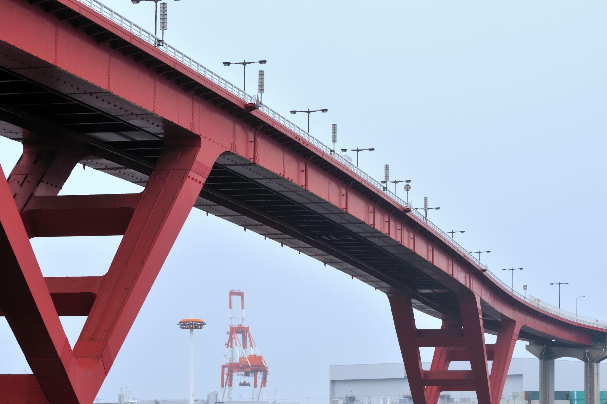
Fiber-optic sensors also play an important role in assessing the health of large structures—such as bridges, buildings, tunnels, and dams—through SHM (Structural Health Monitoring).
Fiber-optic sensors are extremely compact and lightweight and can even be embedded within structures. Because they do not use electricity, they are not affected by lightning strikes or strong electric fields, enabling safe, long-term monitoring.
They enable multi-decade aging monitoring and direct measurement deep inside structures—difficult with conventional electrical strain gauges—making them well-suited for concrete strain measurement and monitoring strain in steel-frame structures.
In fact, since fiber-optic sensors were first introduced for monitoring concrete bridges in the late 1980s, their use has expanded to monitoring strain and displacement in bridges and tunnels, building-tilt monitoring, fire monitoring, and more.
Demonstrations are advancing in infrastructure maintenance, including systems that place optical fibers along railway rails to detect train passage and anomalies from strain changes, and applications of FBG sensors for monitoring tension in bridge cables.
Aerospace

Adoption is also advancing in aircraft, rockets, and satellites. Aircraft must ensure safety through structural health monitoring that continuously tracks stress and vibration during flight, which traditionally required numerous electrical sensors and extensive wiring.
With fiber-optic sensors, a single thin fiber can measure strain and temperature at multiple points across the airframe simultaneously, greatly contributing to weight reduction and simplified wiring.
Research includes structural health monitoring systems for composite wings with multiple embedded FBG sensors, and tests are being conducted toward real-time monitoring during aircraft operation.
In space applications as well, fiber-optic sensors are beginning to be used to monitor temperature and stress in satellites and rocket engines. Because optical fibers are lightweight and easy to route, they are well suited to confined cabins and spacecraft interiors, and are expected to become indispensable for future aerospace condition-monitoring systems.
Switches for High Vacuum Class
- GN Switches-
High vacuum at 10-5Pa with low outgassing
Click here ›Energy industry

Fiber-optic sensors also play an important role in energy-related sites. In the oil and gas industry, systems that insert optical fibers into wells to measure deep temperature and pressure in real time have been commercialized.
Traditionally, it was difficult to deploy sensors deep underground, but with optical fibers, even a narrow bore can deliver sensors several kilometers down. Using FBGs and distributed temperature sensors (based on Raman scattering) that can operate under high temperature and high pressure, well conditions are monitored.
Deployment is also advancing for distributed acoustic sensing (DAS), which buries optical fiber cables along long-distance oil pipelines to detect vibrations caused by leaks or impacts.
Because it can precisely identify where along pipelines—spanning tens of kilometers—an abnormal event occurs (leakage, impact, unauthorized intrusion, etc.), it is effective for preventing environmental contamination and theft.
In the power sector, fiber-optic sensors are used on large substation transformers to detect internal temperature rise, and optical current sensors that measure magnetic fields generated by current in transmission lines via the Faraday effect have been commercialized.
Under the harsh environmental conditions typical of the energy industry, fiber-optic sensors are becoming established as safe and reliable monitoring tools.
Advantages and disadvantages compared with other sensor technologies
Below is a summary of the distinctive advantages and drawbacks of fiber-optic sensors compared with common sensor technologies (such as electrical temperature and strain sensors).
Key advantages of fiber-optic sensors
Immune to electromagnetic noise
Because they operate using optical signals, they are essentially unaffected by electromagnetic induction or radio-frequency noise (EMI/RFI), maintaining measurement accuracy even under strong electric/magnetic fields or near high-voltage lines. This is a major advantage over conventional electrical sensors that are vulnerable to lightning surge and induced noise.
Safe to use in hazardous environments
Optical fibers are non-conductive and do not generate ignition sources (sparks), so they can be used safely in explosion-proof environments filled with gasoline vapor or gas. They are also radiation-resistant, chemically stable, and corrosion-resistant (as glass media), making them suitable for harsh measurement environments such as inside nuclear reactors or chemical plants.
Compact, lightweight, and well-suited for long-distance transmission
Because fiber-optic sensors are extremely thin and lightweight, embedding or attaching them to structures and equipment does not cause obstruction. With low signal attenuation, optical signals can be transmitted over distances of tens of kilometers, which is advantageous for remote monitoring.
Multipoint sensing on a single fiber
Using wavelength-division multiplexing and time-division multiplexing techniques, it is possible to build a sensor network by connecting multiple sensors in series along a single optical fiber. This enables efficient, low-wiring monitoring of a large number of measurement points, providing strong capabilities for wide-area infrastructure monitoring.
High-temperature and high-pressure tolerance
Quartz-glass optical fibers can withstand temperatures exceeding 1000°C, and some specialized sensors—such as laser-processed FBGs—have been reported to operate in environments near 1500°C. They can also perform in high-pressure or deep-sea environments when used in sealed configurations, enabling measurements in extreme conditions that are difficult for conventional sensors.
High sensitivity and wide bandwidth
Because light behaves as a wave, it is excellent at detecting extremely small changes; interferometer-based phase sensors can detect strain on the nano-strain order. In addition, optical fibers can transmit broadband signals, enabling fast response and strong multiplexing performance.
Key drawbacks of fiber-optic sensors
High cost
Fiber-optic sensor systems are generally expensive, with costs driven by the sensing elements themselves and specialized equipment such as interrogators (wavelength analysis units). Although mass production is reducing costs, adoption may still be difficult for applications that demand very low cost.
System complexity
They require peripheral devices—such as light sources, detectors, and spectrum analyzers—to generate, detect, and analyze optical signals, which tends to make system architecture more complex than with electrical sensors.
Because adjusting optical components and handling fibers require specialized knowledge, developing capable engineers and applying advanced installation methods can become challenges.
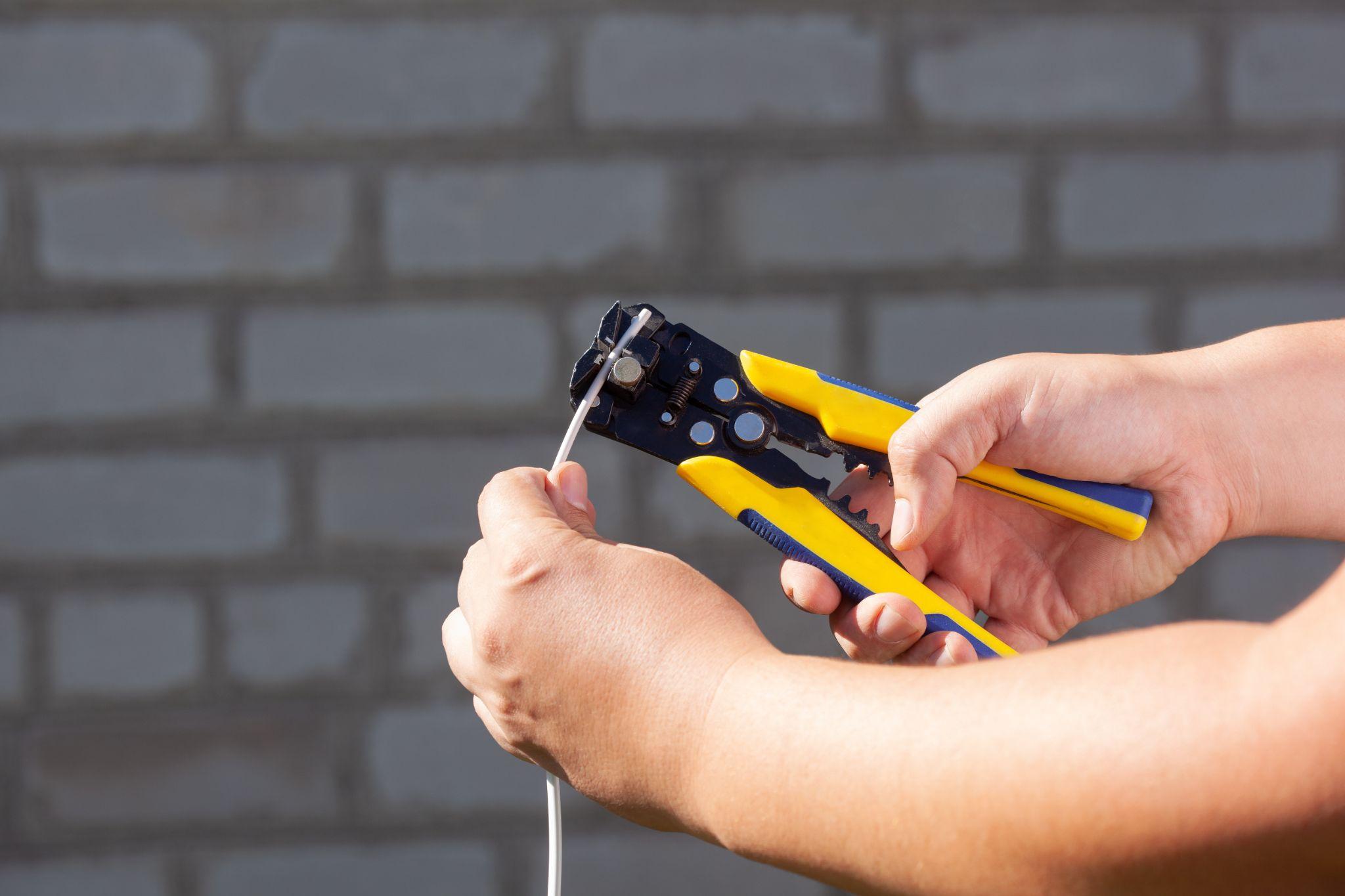
Difficulty of handling optical fibers
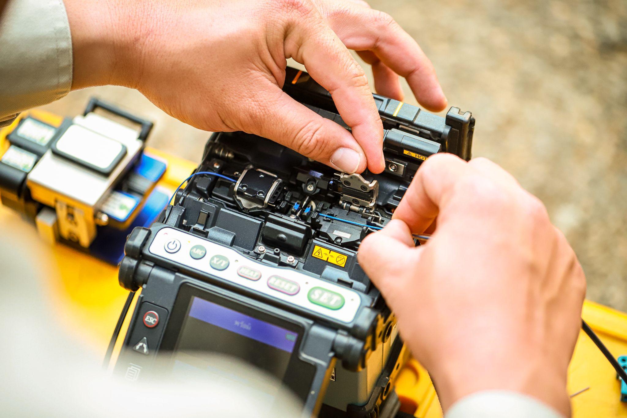
Optical fiber, a thin glass filament, is vulnerable to bending and tensile stress and carries a risk of breakage. During on-site installation and routing, careful handling is required—maintaining the minimum bend radius and providing service loops, for example. Connections can also be more labor-intensive than conventional wiring, requiring dedicated fusion splicers and high-precision connectors.
Integration with other systems can be challenging
Signals from fiber-optic sensors are optical. To connect directly to conventional electrical measurement systems or control systems, an interface is needed to convert them into electrical signals.
In hybrid configurations combining different sensor types, this difference in signal format can become a bottleneck and make integration difficult.
In terms of standardization and interoperability, cross-industry standard development also tends to lag behind what is available for electronic sensors.
High Precision Positioning
- MT-Touch Switches-
0.5 μm repeatability without amplifier IP67, highly resistant to adverse environments
Click here ›Practical points on fiber-optic sensors from experienced users
Here are practical considerations to keep in mind when working with fiber-optic sensors, from the perspective of real-world experience.
Environments where adoption should be considered
Fiber-optic sensors deliver their greatest value in special environments where conventional sensors cannot measure reliably. A particularly effective use case is temperature measurement around high-frequency induction heating systems. Induction heating involves high-frequency currents from tens of kHz to several MHz, and the resulting electromagnetic noise often makes thermocouples and resistance temperature detectors unusable.
For example, it becomes possible to monitor workpiece temperature in an induction heating furnace for a forging line using FBG sensors and perform high-precision control.
They are also effective in plasma cutting and laser processing environments. In intense electromagnetic environments created by plasma arcs, standard temperature sensors can instantly output abnormal values, whereas fiber-optic sensors can measure stably. They are especially useful for managing preheating temperature in thick-plate cutting and for monitoring plate temperature that directly affects cutting quality.
They can also be essential for displacement measurement near large motors and inverter equipment. Switching noise from inverters in the hundreds-of-kW class can cause malfunctions in magnetic sensors and photoelectric sensors, but fiber-optic sensors are unaffected.
They can also be used for vibration monitoring at motor bearing sections and for measuring thermal displacement of spindles in large machine tools.
Working with specialists and building an internal support structure
Because fiber-optic sensors require optical expertise, deploying them solely in-house can be difficult. The key to success is partnering with a reliable specialist. It is important to choose a provider that can deliver end-to-end support—not only selling sensors, but also conducting on-site surveys, selecting the optimal sensors, and handling calibration and maintenance.
When selecting a provider, prioritize a proven track record in your industry. Fiber-optic sensor characteristics vary greatly by application, so it is best to avoid vendors without experience in the machine-tool domain.
Internally, developing a dedicated owner is essential. Fiber-optic sensors require specialized knowledge such as optical wavelength analysis, which may be difficult for electrical maintenance personnel to handle alone.
For example, you might assign one dedicated person from the mechanical design department and have them attend external training for six months.
Practical cautions for installation and operation
For fiber-cable routing, strict compliance with the minimum bend radius is the most critical requirement. For a standard 0.9 mm diameter cable, the minimum bend radius is 30 mm. If you go below this, optical loss increases sharply and measurement accuracy degrades.
When routing inside machinery, verify cable routes in advance using 3D CAD and design paths that ensure sufficient bend radius.
For use in high-temperature environments, cable protection is essential. Standard nylon-jacket cables are typically limited to around 80°C, so near hot zones you should combine stainless protective tubes or ceramic sleeves. Especially near furnace bodies, radiant heat can embrittle cables, making the use of heat shields mandatory.
To ensure connection reliability, standardize on dedicated connectors. With optical fibers, general-purpose screw connections often produce unstable connection quality, becoming a source of measurement error.
Use dedicated optical connectors such as FC/APC or SC/APC types, and ensure long-term stability by keeping connection loss at 0.3 dB or less.
For periodic inspections, perform a monthly transmission-loss check using an optical power meter. If loss degrades by 1 dB or more from the baseline at installation, inspect and clean the cables. Because contamination on connector end faces is a primary cause of measurement error, make wiping with a dedicated cleaning kit a standard task.
How to choose and combine with other sensors
When deciding whether to adopt fiber-optic sensors, carefully assess necessity. Introducing them simply because they are “high precision” often leads to failure, and there is no need to use expensive fiber-optic sensors for applications that conventional sensors can handle. As an example of decision criteria, consider fiber-optic sensors only if at least one of the following applies: (1) electromagnetic noise level of 30 V/m or higher, (2) operating temperature of 200°C or higher, (3) explosive atmosphere, or (4) simultaneous multipoint measurement (10 points or more). For other common uses, magnetic sensors or photoelectric sensors often offer better cost performance.
What Are Metrol’s High-Precision Positioning Sensors?
While fiber-optic sensors offer excellent characteristics such as immunity to electromagnetic noise and high-temperature capability, they have limitations when it comes to mechanical positioning at the μm (micrometer) level.
In particular, when aiming to improve machining accuracy and shorten setup time on machine tools, there are many cases where precise contact detection is required—beyond what non-contact sensors alone can handle.
For such applications, dedicated sensors that are contact-based yet can achieve repeatability of 1 μm or less deliver strong performance. Below, we introduce Metrol’s sensor products specialized for high-precision positioning at the micrometer level.
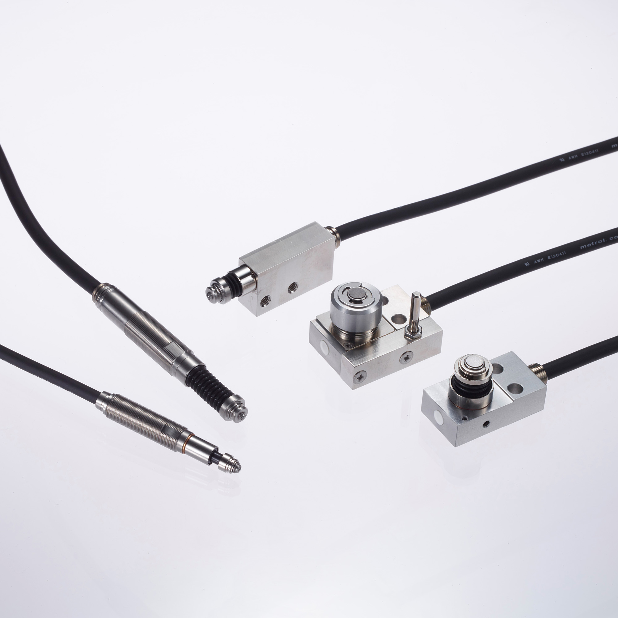
High-Precision Positioning Touch Switches
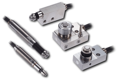
These are contact-type high-precision switches used for positioning and workpiece presence detection in machine tools, robots, and jigs. They achieve an extremely high repeatability of up to 0.5 µm and feature IP67-rated waterproof and dustproof protection, ensuring stable operation even in harsh environments. With more than 200 standard models available, they offer a wide range of variations, including designs for confined spaces, high-temperature environments, vacuum applications, and low contact force requirements.
Tool Setter (Tool Length Measurement Sensor)
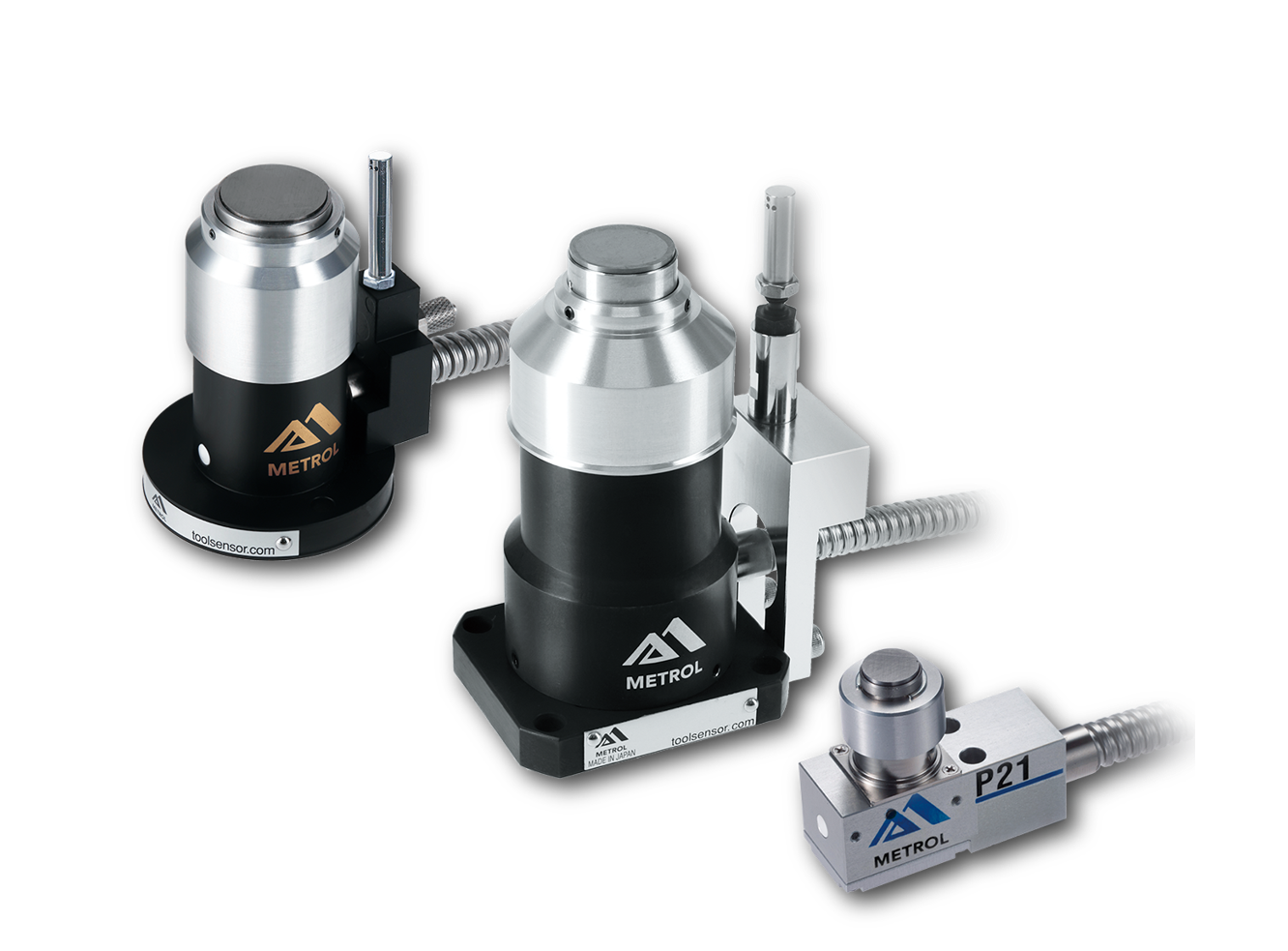
This is a contact-type sensor installed on CNC machine tools and industrial robots for tool length measurement, reference position setting, and tool breakage detection. By automatically measuring and compensating for tool length, wear, and thermal displacement inside the machine, it helps prevent machining defects and significantly reduces setup time. It is one of Metrol’s best-selling products, with a proven track record of more than 500,000 units shipped in 74 countries worldwide.
Touch Probe (On-Machine Measurement Probe)
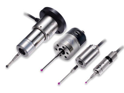
This is a contact-type probe for in-machine measurement, installed on machine tools and robots to automatically perform workpiece positioning (centering) before machining and dimensional measurement after machining. With a repeatability of 1 µm, it automates workpiece referencing and dimensional inspection, replacing skilled manual operations to reduce setup time and help prevent machining defects. Both wired and wireless models are available, meeting retrofit needs for 5-axis machining centers and robotic applications.
Air Gap Sensor (Pneumatic Sensor)
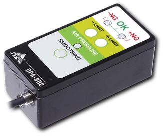
This is a non-contact sensor that uses air pressure to detect workpiece seating conditions with micron-level accuracy. It can detect gaps (“lift”) of less than 10 µm—previously difficult to measure—with a repeatability of ±0.5 µm, helping prevent machining defects and equipment downtime caused by insufficient contact between the workpiece and fixture. The sensor is used in applications such as semiconductor manufacturing processes, precision part clamping operations, and grinding wheel positioning on grinding machines, and it is a smart sensor that also supports the international standard IO-Link communication.