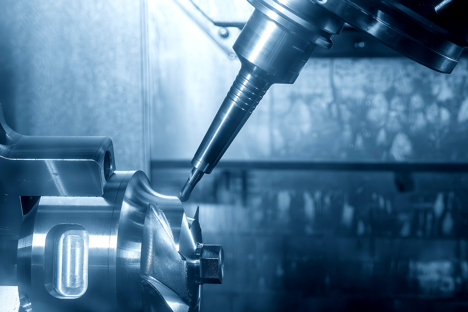
What Is a Gear Cutting Machine? An Easy-to-Understand Guide to Types and Features
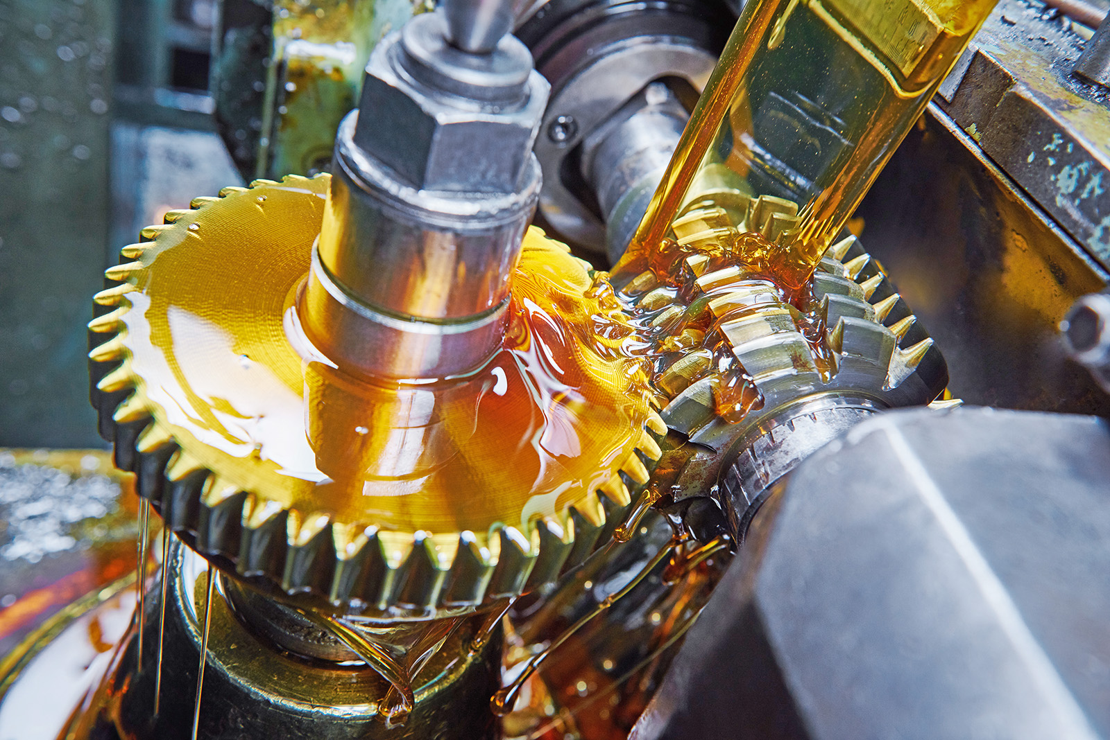
Key Points
- Gears are important machine components used to transmit power
- Gear machining is broadly classified into generating methods and form cutting methods
- Gear skiving is also attracting attention
Source: "Hajimete no Kousaku Kikai"
Table of Contents
What Are Gears?
1. Features
Gears are one of the most important machine elements, and some type of gear is used in most machinery. Gears have a long history and are said to have been used in devices such as water-lifting mechanisms since ancient times.
The functions of gears can be summarized into three main roles: (1) transmitting power, (2) changing rotational speed and torque, and (3) changing the direction of rotation.
Gears are generally used to transmit rotational power from devices such as motors from one shaft to another. Other power transmission components include belts and roller chains used in bicycles. However, gears have a relatively simple structure and provide low transmission loss. In addition, gears are available in a wide range of sizes, from miniature gears used in watches to large gears used in ship turbines, making them widely adopted in machinery.
A single gear cannot function on its own. Power is transmitted to another shaft through the meshing of two or more gears. By changing the ratio of the number of teeth between meshing gears, the rotational speed of a motor can be adjusted freely. This ratio is called the reduction ratio.
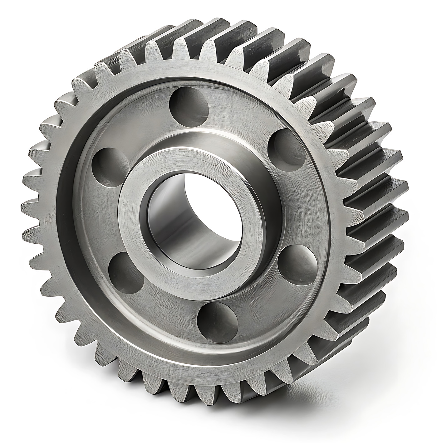
When gears are used to reduce rotational speed, higher torque can be obtained in return. A device that utilizes the reduction ratio of gears is called a reducer, and reducers are widely used across many industries, particularly in automobiles and industrial robots. In addition, depending on the combination of gears, the direction of motor rotation can also be changed.
The number of teeth and tooth size are important factors when considering the reduction ratio. Gear size is indicated by a parameter called the "module." The larger the module, the larger the teeth. In addition, the spacing between teeth is called the "pitch," and a larger module results in a larger pitch as well.
The module is expressed in millimeters, while in countries such as the United States, gear size is often indicated using the inch-based "diametral pitch."
For multiple gears to mesh and rotate properly, intentional clearance must be provided between the contact surfaces of the gears. This clearance is called "backlash." Without backlash, gears cannot rotate smoothly. However, excessive backlash can cause noise and vibration and may also affect gear life. Therefore, gears used in machine tools are generally preferred to have minimal backlash.
Automates originating of cutting tools
- Tool Setter -
Tool length and chips are monitored to prevent machining defects due to wear and thermal displacement
Click here ›2. Types
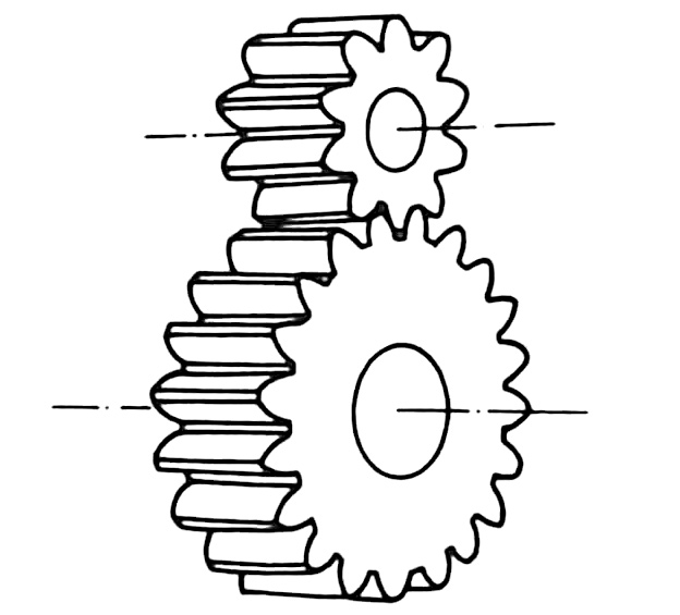
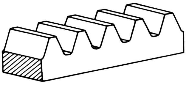
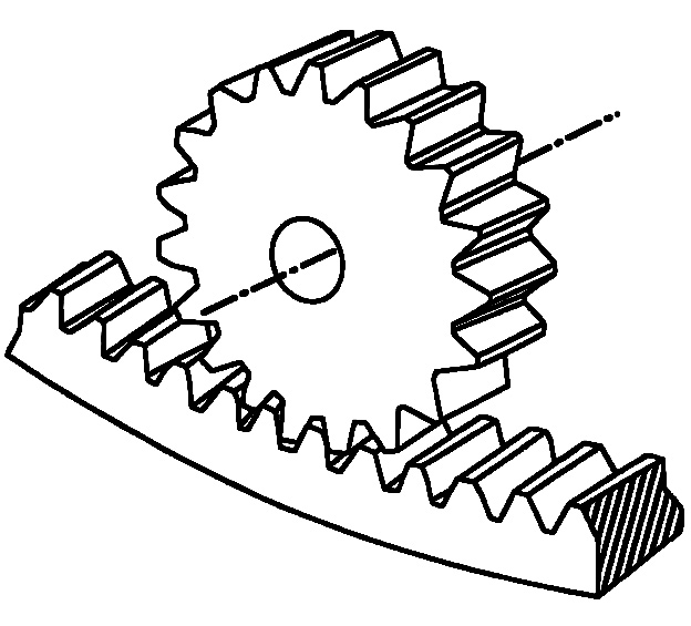
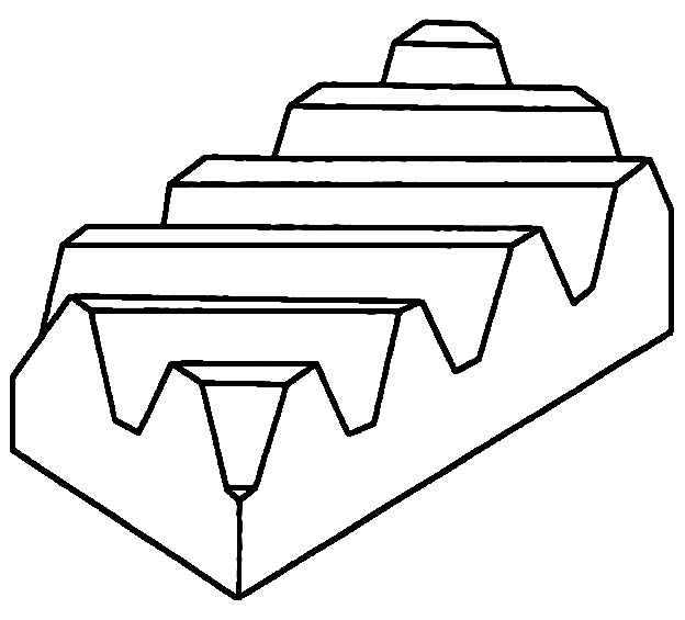
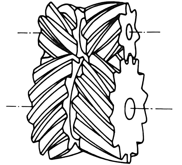
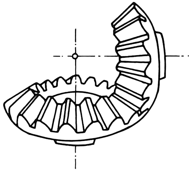
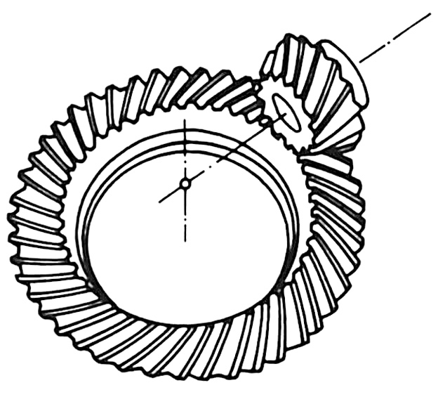
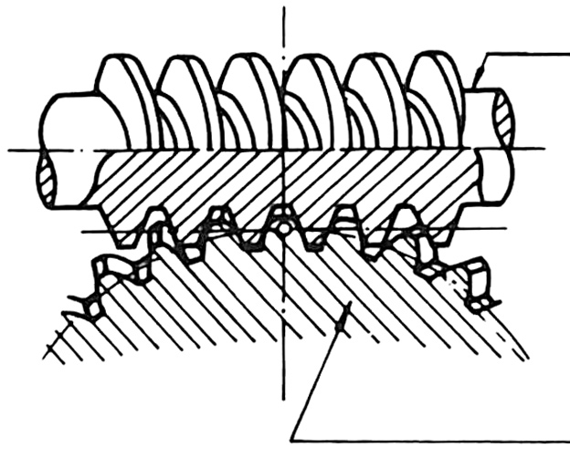
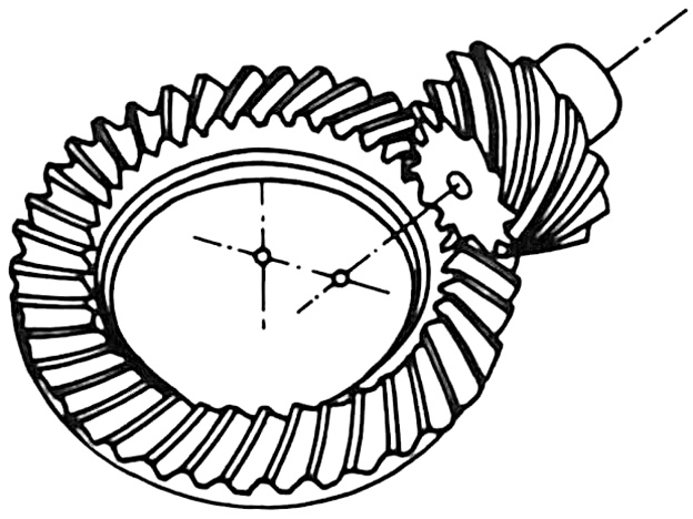
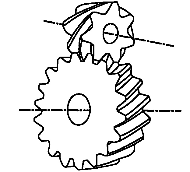
There are many types of gears, including (1) spur gears, (2) racks, (3) internal gears, (4) external gears, (5) helical gears, (6) helical racks, (7) double helical gears, (8) straight bevel gears, (9) spiral bevel gears, (10) cylindrical worm gears, (11) hypoid gears, and (12) screw gears.
Gears can be classified into three types based on the positional relationship of the two shafts that transmit power: parallel shafts, intersecting shafts, and skew shafts. Parallel-shaft gears transmit power between two parallel shafts and include spur gears, racks, and helical gears.
Intersecting-shaft gears transmit power between two intersecting shafts and include straight bevel gears and spiral bevel gears.
Skew-shaft gears are used when two shafts are neither parallel nor intersecting. Examples include cylindrical worm gears and screw gears.
For gears used in general machinery, the tooth profile is typically based on part of a curve known as the involute curve. An involute curve is defined as "the curve traced by the end of a taut string as it is unwound from a cylinder." A tooth profile manufactured using this curve is called an involute tooth profile.
Cycloidal curves may also be used in tooth profile design. This is "the curve traced by a point on a circle as the circle rolls," and it is used in gears for precision devices such as watches.
The required specifications and performance of gears vary depending on the application. For example, automotive transmissions require high speed, high precision, high productivity, compact size, light weight, low vibration, and low noise. Gears for industrial robots emphasize rotational accuracy and ease of control.
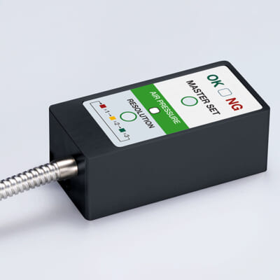
High-precision seating confirmation of workpiece and jig
- Air Gap Sensor -
You can check not only "presence/absence" but also "adhesion (gap)" at the same time with a repeatability of ±0.5 μm.
Click here ›What Is Gear Machining?
Gears are mainly manufactured through cutting and grinding processes. Machining gear tooth profiles by cutting is also referred to as "gear cutting."
Gear cutting and grinding methods are broadly classified into two categories: the generating method and the form cutting method. Other methods, such as template-based gear cutting, also exist. In the template method, the cutting tool follows the curve of a template to directly create the tooth profile. This method is used for machining conical gears such as bevel gears.
In addition to cutting and grinding, gears can also be manufactured through plastic forming methods such as rolling and forging, as well as sintering. These methods are commonly used for mass production of small gears. Sintering is a process in which metal powder is heated and compacted into a desired shape.
1. Generating Method
The generating method uses tools such as rack cutters, pinion cutters, and hob cutters to machine tooth profiles on a workpiece. A rack cutter is a flat tool with tooth grooves. A pinion cutter resembles a spur gear, while a hob cutter has multiple cutting edges arranged helically around the outer circumference of a cylinder.
In grinding processes, screw-shaped grinding wheels and similar tools are used. The grinding wheel meshes with the workpiece to grind the tooth profile with high precision.
A key feature of the generating method is that the tooth profile is created through the relative motion between the tool and the workpiece. This method is suitable for efficiently machining high-precision gears. Many gear cutting machines and gear grinding machines described later adopt this method.
2. Form Cutting Method
The form cutting method uses a tool pre-shaped to match the desired tooth groove profile and machines the gear teeth one by one on the workpiece. Even without a dedicated gear cutting machine, gear cutting can be performed using machining centers (MCs) and other general-purpose machine tools, making this method highly versatile.
In grinding applications, grinding wheels shaped to match the tooth groove are used to grind each groove individually. With an indexing device, complex mechanisms are unnecessary, simplifying the machine structure. Grinding efficiency is also high, making this method suitable for mass production. Indexing refers to accurately rotating the axis to a specified angle.
What Is a Gear Cutting Machine?
A gear cutting machine is a general term for machine tools used to machine gear tooth profiles. Since tooth profiles vary greatly depending on the type and characteristics of the gear, many types of gear cutting machines are available.
Among them, the most representative are gear cutting machines such as hobbing machines and gear shapers. These machines use rack cutters, pinion cutters, and hob cutters to machine tooth profiles through cutting processes.
There are also machines such as gear grinding machines and gear honing machines that finish tooth profiles through grinding. Gear chamfering machines may also be used to round the corners of gear teeth.
1. Hobbing Machine
A hobbing machine is a machine tool that performs gear cutting using a hob cutter and is widely used as one of the most common gear cutting machines. The hob cutter and workpiece rotate synchronously during machining.
Machining with rack cutters and pinion cutters is less efficient because the tool repeatedly moves up and down during cutting. In contrast, hob cutters can continuously cut into the synchronously rotating workpiece while rotating, enabling highly efficient gear machining. Hobbing machines are widely used in gear manufacturing, particularly in the automotive industry.
NC hobbing machines can numerically control the synchronized rotation of the hob spindle and work spindle, as well as the feed motion of the hob cutter. Some models feature a swiveling hob spindle, enabling the machining of angled tooth profiles such as helical gears.
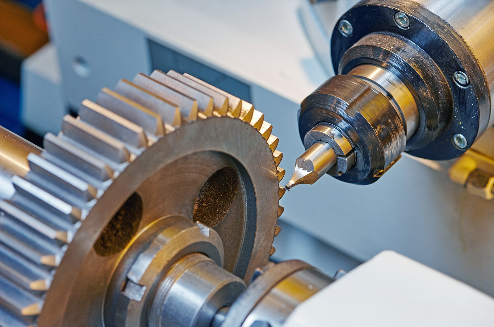
The rigidity of the NC hobbing machine itself greatly affects machining accuracy. As a result, active research and development efforts are underway to reduce machine size without sacrificing rigidity, while also improving precision and productivity.
To improve productivity, higher rotational speeds for the hob spindle and work spindle are also being pursued. However, higher speeds can shorten the life of the hob cutter. Countermeasures such as the use of long-life small-diameter multi-groove hob cutters are therefore being implemented.
2. Gear Shaper
A gear shaper is a machine that uses rack cutters or pinion cutters to machine gears. Machines used for spur gears and helical gears are generally classified into Maag-type and Fellows-type systems. Another key feature is the ability to machine internal gears with tooth grooves on the inside of the workpiece, which cannot be processed by hobbing machines. Gear shapers are also referred to as "gear shapers."
The Maag-type machine is a representative gear shaper that uses a rack cutter. The rack cutter reciprocates vertically while machining the rotating workpiece. It provides high accuracy and is especially effective for machining large gears, achieving precise tooth profiles and lead accuracy. When machining helical gears, the cutter head holding the rack cutter is tilted according to the helix angle, allowing machining in a manner similar to spur gears.
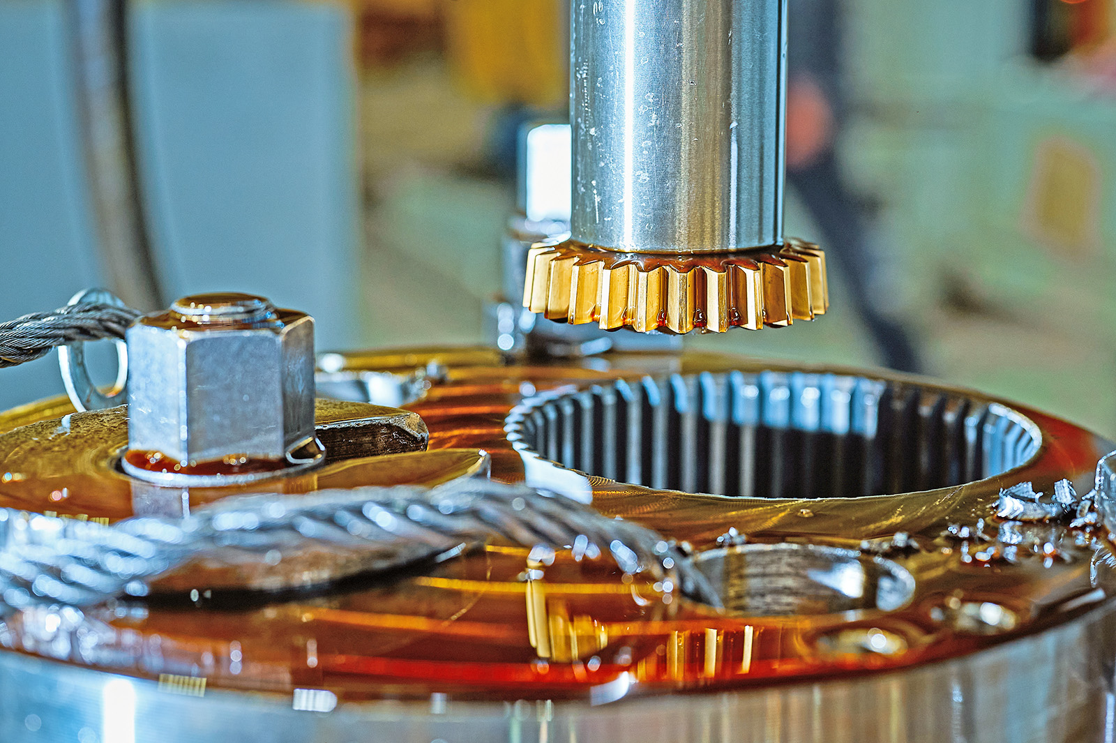
Since a rack cutter is a linear tool, it must return to its original position after each stroke. As a result, machining accuracy is high, but machining efficiency is relatively low.
The Fellows-type machine is a representative gear shaper that uses a pinion cutter. The pinion cutter reciprocates vertically while cutting into the rotating workpiece. Unlike rack cutters, the circular shape of the pinion cutter allows continuous machining.
Other types of gear shapers include bevel gear cutting machines used for manufacturing bevel gears.
3. Gear Grinding Machine
A gear grinding machine is used to grind hardened gears after heat treatment. Hardening is a type of heat treatment that increases the hardness of metal. Hardened gears become extremely durable and can withstand high-speed rotation and heavy loads.
As with gear cutting, grinding methods are classified into generating methods and form grinding methods. Generating methods are widely used, with the Reishauer-type and Maag-type systems being representative examples.
The Reishauer-type system uses a screw-shaped grinding wheel. Similar to hobbing, the grinding wheel and workpiece rotate synchronously, and grinding is performed through their meshing motion. This method is characterized by high grinding efficiency.
The Maag-type system grinds gear teeth by placing them between two dish-shaped grinding wheels and grinding along the inner surfaces of the wheels.
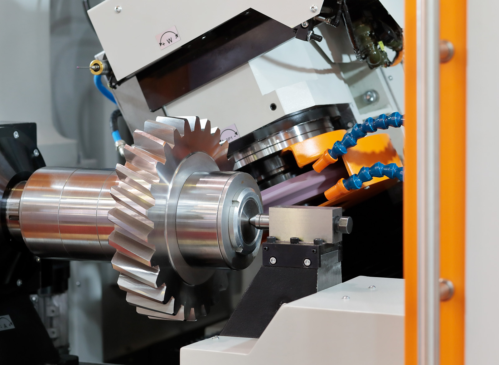
In contrast, the form grinding method uses grinding wheels shaped to match the gear tooth profile and grinds each tooth individually.
Automates originating of cutting tools
- Tool Setter -
Tool length and chips are monitored to prevent machining defects due to wear and thermal displacement
Click here ›Gear Skiving
Gear skiving is a type of generating process that applies skiving technology to gear machining. The term "skiving" means "to shave thinly" and refers to a machining method that removes material in thin layers, similar to planing. This technology has recently attracted significant attention.
Gear skiving can machine both external and internal gears, but it is particularly effective for highly efficient machining of internal gears. Internal gears have traditionally been machined using gear shapers, but efficiency was low because rack cutters and pinion cutters relied on vertical reciprocating motion.
In contrast, gear skiving uses a dedicated rotating tool called a skiving cutter, which rotates synchronously with the workpiece while shaving away thin layers of material. This dramatically improves machining efficiency compared with conventional gear shapers.
Another major feature is the ease of modifying the tooth lead, including applying "crowning," which gives the teeth a slight curvature to reduce gear noise.
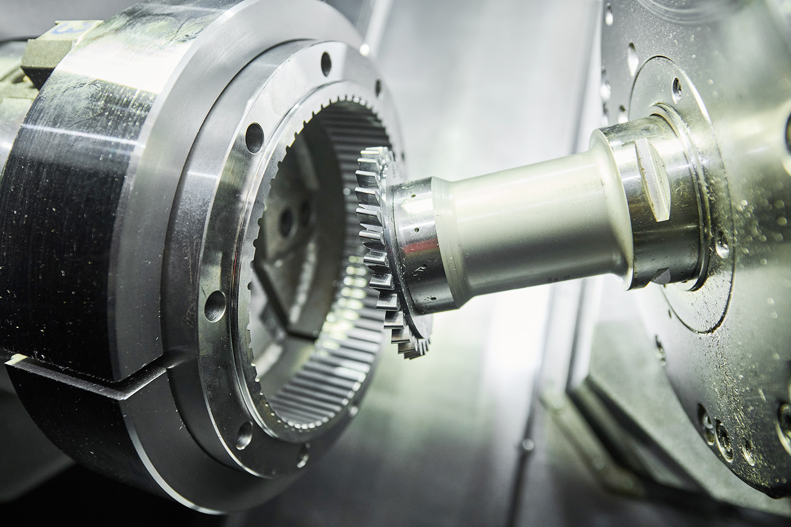
The machining theory behind gear skiving was developed in Germany in 1912 and has a history of more than 100 years. Research and development also progressed in Europe and Japan during the 1970s, but the performance of tools and machines at that time was insufficient for widespread adoption. Although the technology remained largely unused for many years, advances in tooling, machine performance, and control technology have enabled practical implementation, leading to its recent spread.
Today, multiple machine tool manufacturers offer machines capable of gear skiving. In addition to dedicated gear skiving machines, many process-integrated models combine turning, milling, drilling, and other machining methods into a single machine.
With process-integrated machines, operations that previously required multiple machines such as gear cutting machines and lathes can now be consolidated into a single unit, significantly reducing floor space requirements.
Several machine tool manufacturers are also proposing technologies that enable gear skiving on general-purpose machine tools rather than dedicated gear skiving machines. By installing dedicated software and mounting a skiving cutter, gear skiving can be performed on versatile machine tools as well.
However, because the skiving cutter rotates at an angle relative to the workpiece, the process is limited to certain machines such as 5-axis machining centers and multi-tasking machines.
Source: "Hajimete no Kousaku Kikai"
High Precision Positioning
- MT-Touch Switches -
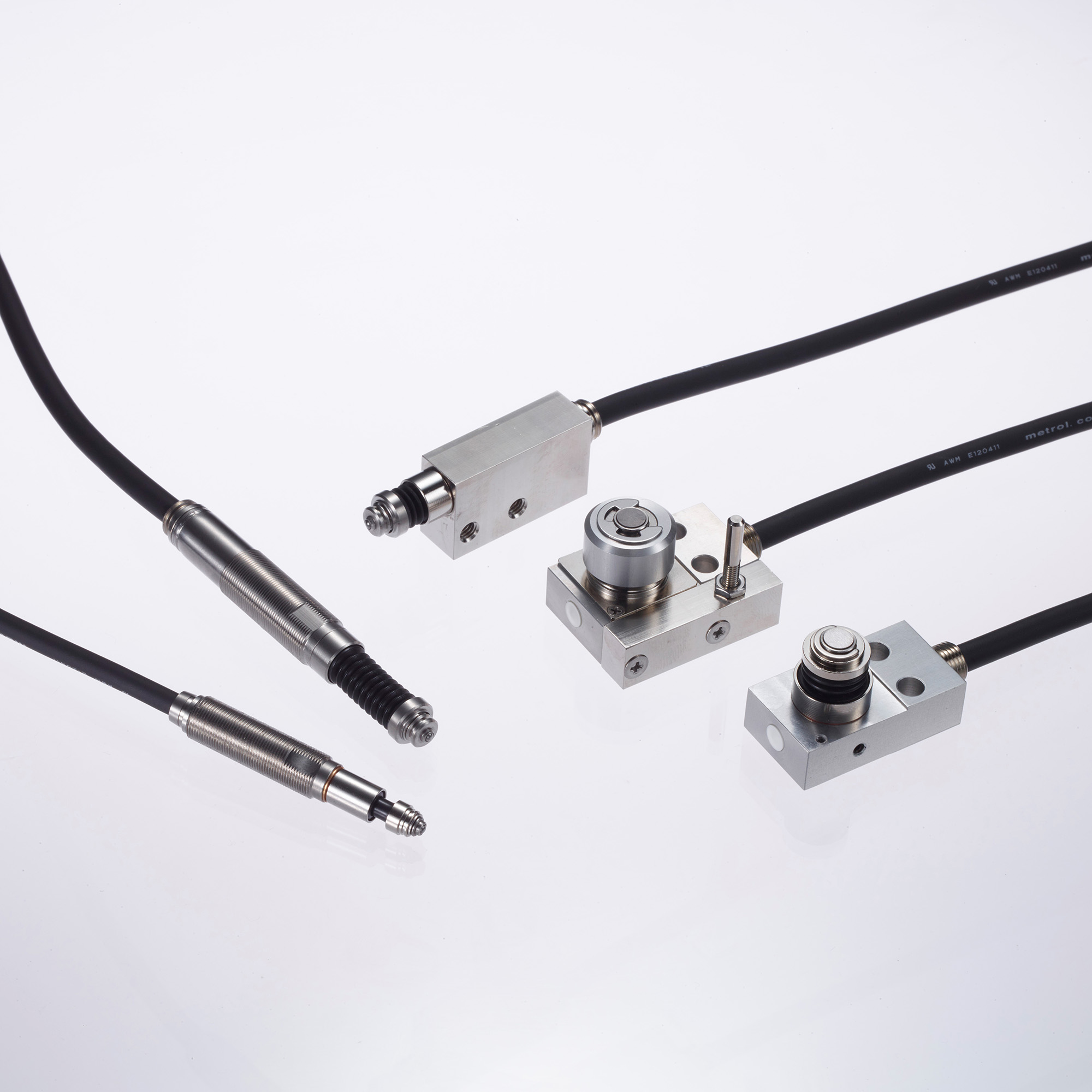
0.5 μm repeatability without amplifier IP67, highly resistant to adverse environments
Click here ›Sensor Implementation Examples
Consistent non-contact detection of 10μm float of shaft components
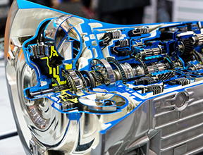
This automotive parts manufacturer produces special gears for a major automobile manufacturer.
A representative from the engineering department consulted us regarding "seating confirmation" for special gear shaft components during drilling operations.
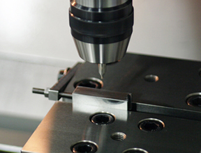
Detection of tool wear by CNC machining center has realized the improvement of the machining accuracy
This precision machining manufacturer produces precision components for a major aerospace manufacturer.
A representative from the cutting department consulted us regarding tool wear detection during machining center cutting operations.
[Video]
【A must-see for CNC Users】Automate Tool Measurement High-PrecisionTool Setter
Related Articles
What Is a Multitasking Machine?An Easy-to-Understand Guide to Its Types and Features
A multi-tasking machine is a general term for machine tools that integrate multiple machining methods with different functions and characteristics into a single unit, such as turning, which machines a rotating workpiece using a cutting tool, and milling, which machines a fixed workpiece using a rotating cutting tool.
Some models can also mount tools such as hob cutters and gear skiving cutters, enabling turning, milling, and gear machining on a single machine.