Cutting Tool Breakage Basics: Setting Machining Conditions and Solving Common Problems
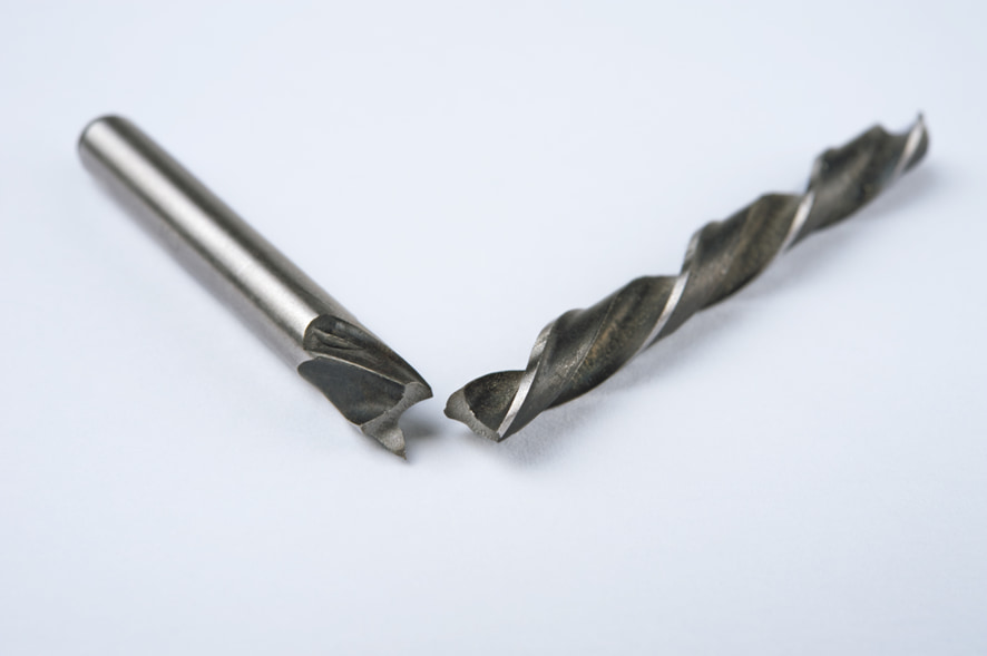
Anyone involved in machining has likely experienced tool breakage at least once. Tool breakage refers to a phenomenon in which a cutting tool suddenly breaks or deforms during machining.
Many people assume that because tools are consumables, breakage is simply unavoidable.
However, by understanding why breakage occurs, it is possible to reduce product loss and excessive tool consumption caused by breakage.
This article clearly explains the main causes of tool breakage and the measures that can be taken to prevent it.
Table of Contents
Basic Understanding of Cutting Tools
Because cutting tools must be selected according to the required machining geometry and accuracy, they are available in a wide variety of types and materials. The tools listed below are representative tools essential to machining operations.
Types and Characteristics of Cutting Tools
Milling Cutters
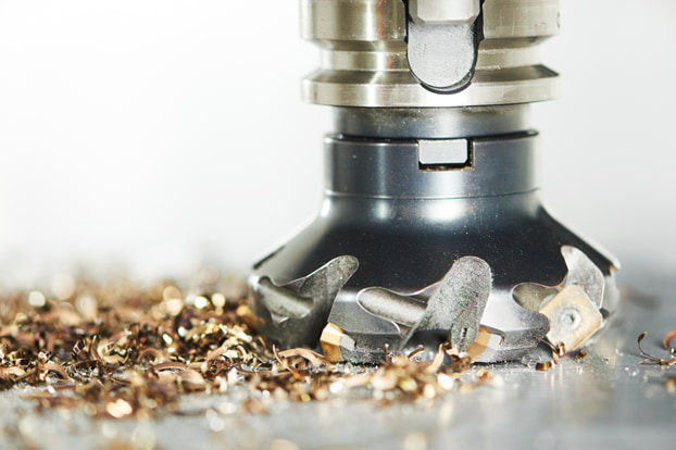
Tools such as end mills and face mills, mainly used on milling machines and machining centers.
They can machine flat surfaces, side faces, and more, and are available in high-speed steel, carbide, and indexable insert types.
Drills
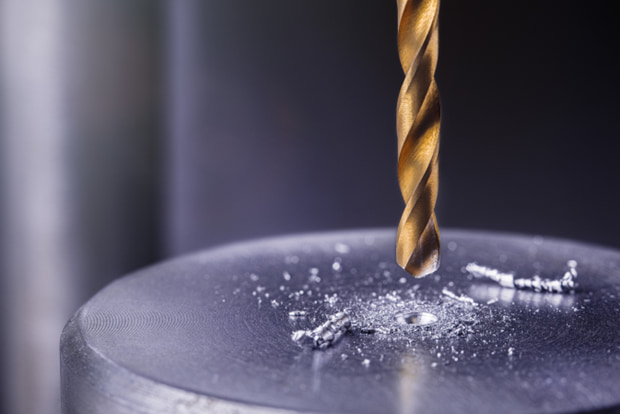
Tools used for hole-making operations on drill presses, lathes, machining centers, and CNC lathes.
The main tool materials are high-speed steel and carbide. In addition to indexable and replaceable-tip types, there are also counterbore drills, step drills, and gun drills specialized for deep-hole machining.
Taps
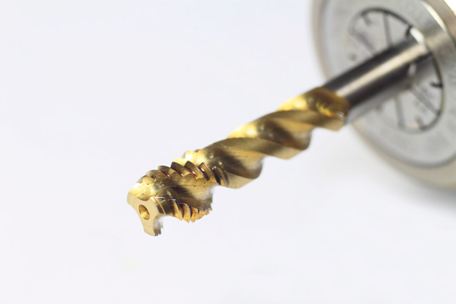
Tools used to machine internal threads, including point taps for through holes and spiral taps for blind holes. They are mainly used on drill presses equipped for tapping and on lathes.
They are available in high-speed steel and carbide, and thread mills that use helical interpolation on machining centers are also used.
Reamers
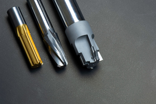
Tools used to precisely finish the inner diameter and surface quality of holes previously machined with a drill.
They are available in high-speed steel and carbide, and depending on the pilot hole shape, there are types for through holes and blind holes.
Mill reamers, which have end-cutting edges at the tip, enable highly accurate positioning and can reduce machining time by reducing the number of tools required.
Turning Tools
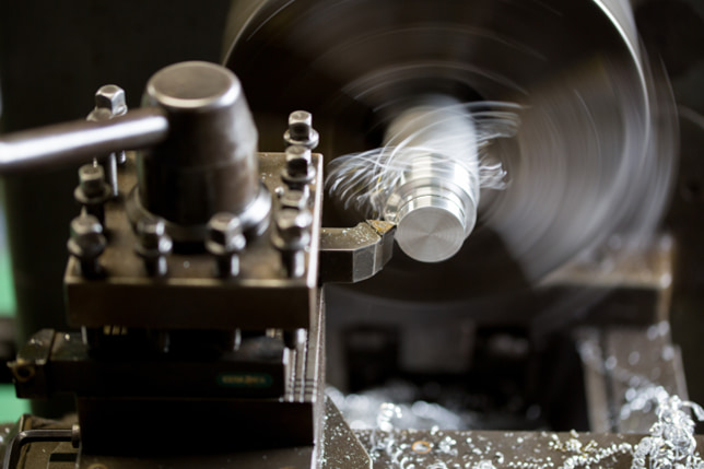
Turning tools are commonly used in turning operations and include types suited to specific machining profiles, such as single-point tools, pointed tools, parting tools, boring tools, and threading tools.
Carbide and indexable types are common, but high-speed steel indexable inserts suitable for threading at low cutting speeds are also available.
About Tool Materials
High-Speed Steel
High-speed steel is a common tool material with advantages such as low cost, easy availability, resistance to edge chipping, and reduced chip scattering during cutting.
It is tougher and less expensive than carbide, but it is less resistant to high temperatures and is not suitable for hardened, high-hardness work materials.
Carbide
Because carbide has higher hardness and heat resistance than high-speed steel, it can be used for high-speed dry machining, but it is more likely to fracture under strong impact.
By selecting a carbide grade and machining conditions suited to the work material and its hardness, stable machining with long tool life can be achieved.
CBN
CBN is a tool material made from the synthetic material cubic boron nitride and is mainly used for finish machining of hardened ferrous materials. Although it is extremely hard, it is prone to cracking and chipping and is also vulnerable to thermal shock, so dry cutting with a small depth of cut is the basic approach.
Diamond
Diamond has extremely high hardness, and compared with carbide tools, built-up edge is less likely to form, enabling long tool life and stable machining.
It is suitable for cutting non-ferrous metals such as aluminum, but because the carbon in diamond has high chemical affinity with iron, it is not suitable for machining ferrous work materials.
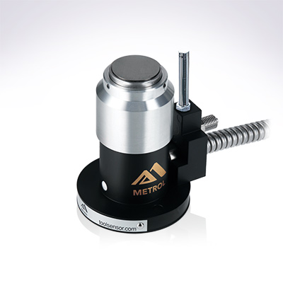
Automates originating of cutting tools
- Tool Setter -
Tool length and chips are monitored to prevent machining defects due to wear and thermal displacement
Click here ›Basic Causes of Tool Breakage
There are three basic causes of cutting tool breakage.
【Mechanical Factors】
- Loads that exceed the tool’s strength
- Unexpected vibration
- Tool holding condition
Mechanical factors are problems related to the physical forces and motion involved in machining.
If the cutting speed or feed rate is too high, the tool may be subjected to a load beyond what it can withstand. Unexpected vibration can also occur due to machine vibration or tool deflection. Improper tool mounting can increase the risk of breakage even under normal machining conditions.
【Material Factors】
- Incorrect selection of tool material for the work material
- Incorrect selection of tool material for the hardness or ductility of the work material
- Overload and vibration caused by the workpiece shape
Material factors are problems related to the compatibility between the tool and the work material.
For example, when cutting a high-hardness material, selecting a tool material that is not suitable for it can lead to rapid wear or edge failure.
If the work material has high ductility, chip control becomes more difficult and the load on the tool increases. In addition, when the workpiece shape is complex, unexpected vibration or impact may occur during cutting, shortening tool life.
【Operating Environment Factors】
- Insufficient cooling
- Improper coolant selection
- Chip clogging
Operating environment factors are problems related to the surrounding conditions during machining. If the temperature at the cutting point rises too high, tool strength decreases and wear progresses rapidly. Using an inappropriate coolant prevents effective cooling and lubrication, shortening tool life. In addition, if chips are not discharged properly, they can accumulate in the cutting area, create abnormal loads, and cause tool breakage.
Types of Breakage Patterns
There are several patterns of tool breakage, each with its own mechanism. These are explained below.
Chipping
Chipping is a condition in which the cutting edge of a hard, brittle tool material such as carbide or CBN becomes finely serrated due to chatter or sudden thermal changes.
It tends to occur when the tool hardness is too high relative to the work material, when the feed amount is too large, or during interrupted cutting.
Another cause of chipping is the detachment of built-up edge that has adhered to the cutting edge.
Fracture
Fracture occurs when a large internal stress is generated in the tool during machining and the resulting load exceeds the tensile strength of the tool material. Breakage caused by overload during heavy cutting falls into this category.
Even when the load is below the tensile strength, metal fatigue caused by repeated loading is also a type of fracture.
Plastic Deformation
Plastic deformation occurs when atoms slip along specific crystal planes inside a material, associated with line defects in the lattice called dislocations. Unlike elastic deformation, plastic deformation does not return to its original state over time. When the limit of deformation or the tensile strength limit is exceeded, failure occurs in the form of breakage.
Automates originating of cutting tools
- Tool Setter -
Tool length and chips are monitored to prevent machining defects due to wear and thermal displacement
Click here ›Machining Conditions for Preventing Tool Breakage
When a tool breaks during machining, it can cause various types of damage to both the machine and the workpiece being machined.
To avoid wasting valuable products, tools, and machining time, it is important to set optimal machining conditions to prevent breakage.
Setting Cutting Conditions
Increasing the cutting speed is one effective way to help prevent tool breakage.
However, cutting speed is harder to increase near the center of tools such as drills, end mills, and ball end mills, as well as with small-diameter end mills, so machining conditions must be set with careful attention to effective cutting speed.
Optimizing the tool path and depth of cut, as well as adding upstream processes to equalize cutting volume and reduce load, are also effective measures for preventing tool breakage. However, planning must take into account the economic cost of increased machining time.
Reviewing Machine-Related Factors
The accuracy and mechanical rigidity of the spindle and tool post are also important factors in preventing tool breakage.
Changing the machining program, adjusting and improving prior processes, and reconsidering the workholding method are also effective measures.
In addition, modern simultaneous 5-axis machining centers allow finishing operations that avoid the center of the ball end mill, making it possible to machine without reducing cutting speed.
Using Coolants and Lubricants
Selecting the appropriate coolant is also effective in preventing tool breakage.
By selecting oil-based or water-soluble coolant according to the work material, heat generated during machining can be dissipated, helping to prevent tool wear and built-up edge. For areas where coolant is difficult to reach or for deep machining, choosing machines or tools with through-tool coolant supply is also effective for preventing tool breakage.
Common Problems and Solutions
Finally, let’s look at common tool breakage problems and their solutions.
When the Material Is Too Hard
If the material hardness is too high, consider using carbide, CBN, or diamond tools and set machining conditions with a reduced depth of cut. In addition, when cutting hardened steel, cutting oil can make the tool more likely to slip, so dry machining or the use of a water-soluble coolant is recommended.
Using Coolants and Lubricants
Selecting the appropriate coolant is also effective in preventing tool breakage.
By selecting oil-based or water-soluble coolant according to the work material, heat generated during machining can be dissipated, helping to prevent tool wear and built-up edge. For areas where coolant is difficult to reach or for deep machining, choosing machines or tools with through-tool coolant supply is also effective for preventing tool breakage.
Breakage Caused by Vibration
To prevent breakage caused by vibration, review the tool overhang length and the clamping method.
Using a shrink-fit chuck, which utilizes thermal contraction, is also highly effective for preventing vibration-related breakage. In addition, when using long-shank end mills and similar tools with a collet chuck, cutting off excess shank length in advance can help prevent breakage inside the collet caused by machining vibration.
Breakage Caused by Overheating
To prevent breakage caused by overheating, directional compressed air and an adequate coolant supply are required.
For deep-hole machining or machining in areas where coolant or air has difficulty reaching the cutting point, selecting machines or tools with through-tool coolant supply enables efficient cooling of the cutting edge.
Metrol Tool Breakage Detection Sensor
Tool Breakage Detection Sensor DFM Series
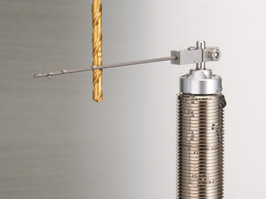
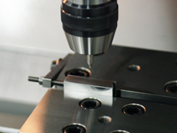
Metrol’s DFM Series tool breakage detection sensor is installed within the machine’s machining area and detects tool breakage using an air-driven needle.
Because it detects breakage by directly contacting the tool with a needle-shaped contact probe, it offers low false-detection rates and reasonable cost even under harsh conditions where coolant and chips are present.
【Video】
Drill Bit Breakage Detection Sensor, DFM series
Related Article
Improving Machining Accuracy with Tool Wear Detection for CNC Machining Centers
Tool length is constantly changing in the harsh operating environment of CNC machine tools, where coolant and chips scatter and where cutting wear, day-night temperature differences, and machine thermal displacement all have an effect.
Metrol’s Tool Setter feeds tool length values back to the NC, enabling tool wear to be detected and compensated with an accuracy of 1 μm.
This eliminates the need for skilled operations such as trial cutting, measurement, and NC data entry, significantly improving machine utilization.