What Is a Machining Center? An Easy-to-Understand Guide to Its Types and Features
Source: "Hajimete no Kousaku Kikai"
Key Points
- A representative type of cutting machine tool
- Machines a fixed workpiece by pressing a rotating cutting tool against it
- Equipped with an NC unit and ATC
Table of Contents
What Is a Machining Center?
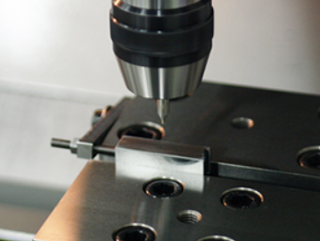
A machining center (MC) is a machine tool that machines a fixed workpiece by pressing a rotating cutting tool against it. Among cutting machine tools, machining centers and lathes are recognized as representative machine types.
Machining centers are used in a wide range of industries, including automotive, aerospace, medical, electronic components, and mold manufacturing.
The four major characteristics of an MC are: (1) the use of rotary tools, (2) numerical control, (3) automatic tool changing, and (4) the ability to perform many machining operations without changing the workpiece setup.
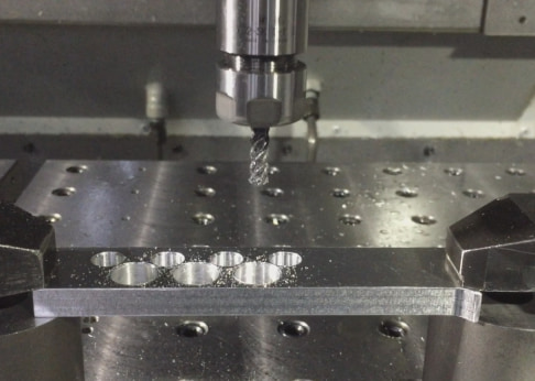
Rotary tools refer to tools such as milling cutters and end mills that machine the workpiece while rotating. The machining method that uses these rotary tools to cut flat surfaces and grooves in a workpiece is called milling.
Another major feature of an MC is numerical control. Numerical control means controlling operations such as the movement of cutting tools and the table, as well as tool changes, using numerical data.
In English, this is called “Numerical Control,” abbreviated as “NC.” Every MC is equipped with an NC unit.
The ability to change tools automatically is also a distinctive feature of an MC. Every MC is equipped with an automatic tool changer. In English, this is called an “Automatic Tool Changer,” abbreviated as ATC.
The ATC stores various tools, including milling cutters and end mills for milling, drills for hole making, and taps for threading, and retrieves them when needed.
Because of the ATC, various operations such as milling, drilling, and threading can be performed after the workpiece is set on the table only once.
Machining centers and lathes are both representative machine tools, but the difference between the two is easiest to understand in terms of the machining method.
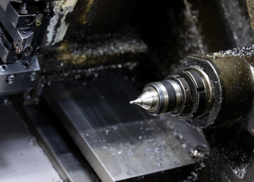
A lathe machines a rotating workpiece by moving a cutting tool fixed on a tool post and pressing it against the workpiece. This machining method is called turning. It is mainly used for machining cylindrical workpieces.
In contrast, an MC uses rotary tools to machine a fixed workpiece. It is suitable for machining plate-shaped or block-shaped workpieces.
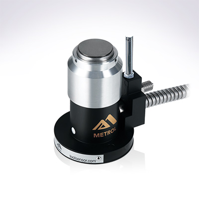
Automates originating of cutting tools
- Tool Setter -
Tool length and chips are monitored to prevent machining defects due to wear and thermal displacement
Click here ›Basic Structure of a Machining Center
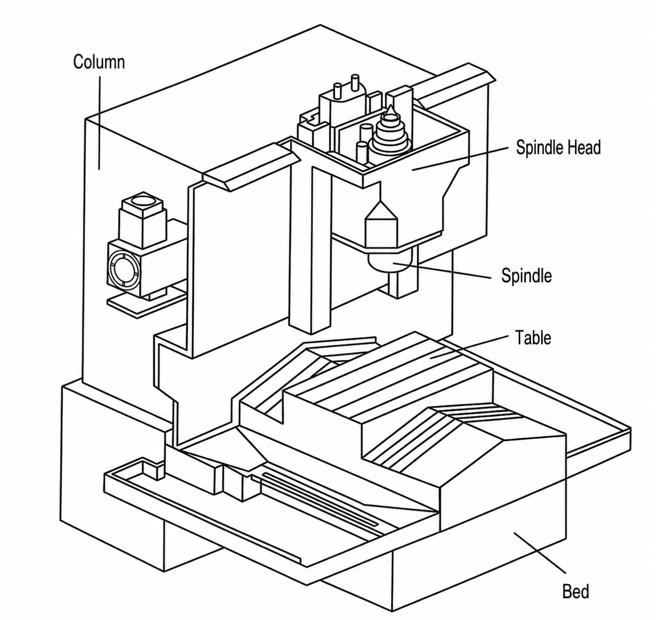
An MC basically consists of (1) spindle head, (2) bed, (3) column, (4) ATC, and (5) NC unit.
1. Spindle Head
This is the section that houses the spindle. It consists of the spindle head body, the spindle itself, and the drive mechanism that rotates the spindle. The tool is mounted on the spindle.
Because an MC machines a workpiece using rotating tools, the accuracy of the spindle directly affects machining accuracy. For this reason, it is positioned as one of the most important components of an MC.
The spindle is required to provide various performance characteristics, including (1) rotational speed, (2) rotational accuracy, (3) torque (torsional strength), and (4) rigidity.
Rigidity is an index that indicates resistance to deformation caused by external forces such as bending and twisting, and it is regarded as an important factor when evaluating machine tool performance.
Servo motors are mainly used to drive the spindle. A servo motor features stepless speed control and can rotate from low speed to high speed with nearly the same torque.
To transmit the rotation of the servo motor, gear-based speed-change mechanisms and fastening components called couplings are used. Recently, built-in motors with the servo motor integrated into the spindle have also been adopted in high-speed MCs and other machines.
Tools are mounted on the spindle via a tool holding device (tool holder), and there are several standards for tool holders.
In Japan, the BT shank is widely used. BT stands for “Bottle Grip Taper” and is recognized as a standard originating in Japan.
A BT shank is characterized by the tapered shape of the shank section—the part of the tool holder that contacts the spindle—which narrows toward the tip.
BT shanks are classified into BT30, BT40, and BT50 according to the diameter of the largest part of the taper.
These numbers also indicate the size of the MC. The larger the number, the larger the BT shank and the larger the MC.
2. Bed
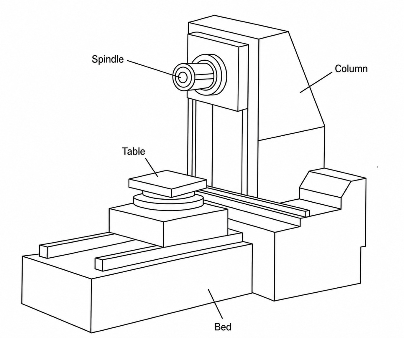
The bed serves as the base that supports the body of the MC. It has guideways that accurately guide the table to the target position.
In cutting operations, large forces and vibrations are generally generated when the cutting tool removes material from the workpiece.
The bed is required to have sufficient rigidity to withstand these forces and high damping capacity to absorb vibration. To increase rigidity, some beds are designed with reinforcing members called ribs placed at various locations.
3. Column
The column is the upright structure installed vertically on the bed. Some columns can move along the guideways on the bed, while others are integrated with the bed.
Metal has a property called thermal displacement, in which dimensions change due to heat, and thermal displacement negatively affects machining accuracy.
For this reason, many machines use columns with a thermally symmetrical left-right structure to minimize the effects of thermal displacement.
4. ATC
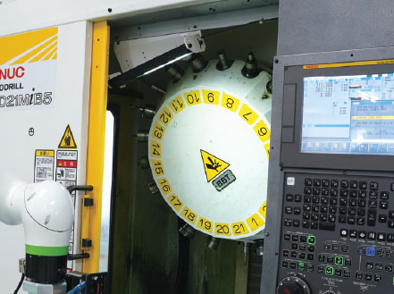
The ATC is a device that automatically changes cutting tools. It consists of a tool magazine that stores the tools and a changer arm that changes the tools in place of human hands.
The tools are stored one by one in the tool magazine. Based on commands from the NC unit, the required tool is called from the tool magazine.
5. NC Unit
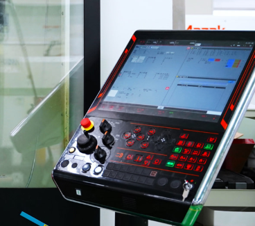
The NC unit serves as the brain of the MC and is responsible for commanding spindle speed and the movement of the table and cutting tools.
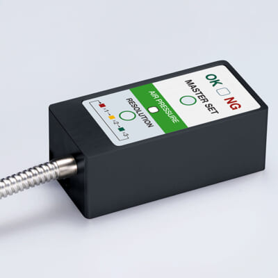
High-precision seating confirmation of workpiece and jig
- Air Gap Sensor -
You can check not only "presence/absence" but also "adhesion (gap)" at the same time with a repeatability of ±0.5 μm.
Click here ›Types of Machining Centers
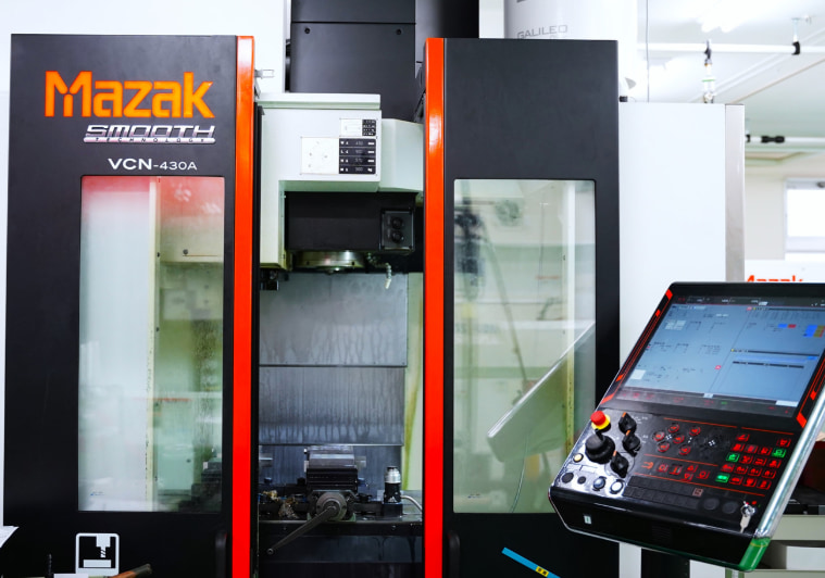
MCs are broadly classified into vertical and horizontal types according to spindle orientation. In addition, there are various other types such as gantry MCs and line-compatible MCs.
1. Vertical Machining Center
(1) Structure
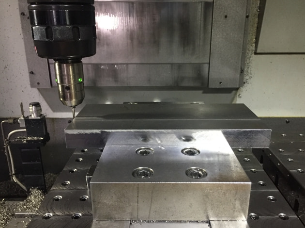
This type of MC has a spindle mounted vertically relative to the ground. It is widely used among MCs and is mainly used for machining small- to medium-sized parts.
In many cases, the table moves in a horizontal plane while the spindle side moves up and down.
However, in large machines, the combined weight of the workpiece and table may exceed that of the column, so there are also types in which the column side moves vertically and front to back.
When viewed from the front of the machine, the vertical direction in which the spindle moves is generally the Z-axis, the left-right direction is the X-axis, and the front-back direction is the Y-axis. These three axes enable three-dimensional machining.
(2) Features
A vertical MC is suitable for machining plate-shaped workpieces with a large machining area per surface, such as molds.
Because the workpiece is machined from above, it is easy to compare the machining drawing with the actual machining point, providing good operability and reducing machining errors.
Another feature is that it is easy to judge the distance between the cutting edge of the tool and the workpiece. It also requires relatively little installation space.
On the other hand, in a vertical MC, the column supports the spindle head, and the spindle projects over the table in a cantilevered structure.
Because cutting resistance during machining acts as a force that tends to lift the spindle head, the column must have sufficient rigidity to prevent a decline in machining accuracy.
Also, because the workpiece is machined from above, chips tend to accumulate easily. To avoid problems caused by chips being caught during machining, the chips must be thoroughly removed using coolant or air blow.
2. Horizontal Machining Center
(1) Structure
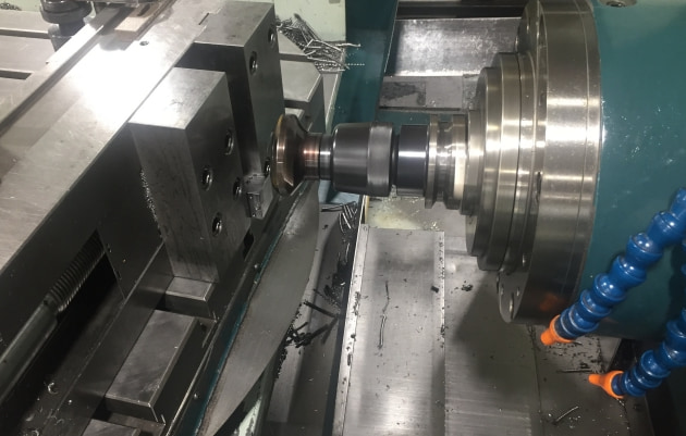
This type of MC has a spindle mounted horizontally relative to the ground. Many models are equipped with a rotating table.
To support long operating hours and line production, some machines are also equipped with an automatic pallet changer (APC). APC stands for “Automatic Pallet Changer.”
When viewed facing the spindle, the spindle direction (front-back) is generally the Z-axis, the left-right direction is the X-axis, and the up-down direction is the Y-axis.
(2) Features
Because the spindle of a horizontal MC is mounted horizontally relative to the ground, chips fall naturally by gravity, making various chip-related problems less likely to occur.
For this reason, it is well suited to long periods of unattended operation and automation using APC and similar systems.
In addition, if the machine has an indexing table that rotates around the Y-axis, four sides of the workpiece can be machined after mounting it on the table only once, resulting in high machining efficiency. Also, by using a jig called an angle plate, many workpieces can be mounted at once for efficient machining. A jig is an auxiliary device used to fix a workpiece to a machine tool.
However, because the spindle is mounted horizontally relative to the operator’s line of sight, it is more difficult to judge the distance between the tool and the workpiece. As a result, setup is more difficult and machining errors are more likely to occur.
3. Gantry Machining Center
(1) Structure
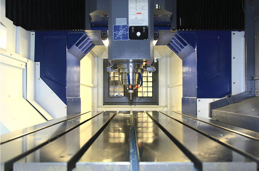
This type of MC forms a gate-like structure with two columns and a cross rail that guides the spindle head. It is also called a gantry-type MC.
Gantry MCs can be broadly divided into two types according to how the spindle and cross rail are driven: the moving cross rail type and the fixed cross rail type.
In the fixed cross rail type, the cross rail and columns are fixed, and the spindle head moves vertically and horizontally. In the moving cross rail type, the spindle and cross rail are fixed together, and the entire cross rail moves.
(2) Features
Gantry MCs excel in machining large workpieces used in industries such as aerospace, shipbuilding, and heavy electrical equipment.
By attaching devices called attachments to the spindle head, a single gantry MC can perform a variety of machining operations, including angled holes. By using different attachments, up to five sides can be machined, excluding the surface in contact with the table.
This type of gantry MC is also called a “5-face machining center.” If five-face machining can be completed in a single setup, the workpiece can be machined efficiently and with high accuracy.
However, because the large spindle head is mounted on the front of the cross rail, the overall weight balance of the cross rail tends to be poor. In addition, because the target workpieces are large, machining time is longer and thermal displacement is more likely to occur. Thermal displacement can cause the column to tilt, leading to reduced machining accuracy. For this reason, many recent gantry MCs are equipped with technologies to suppress thermal displacement.
4. Line-Compatible Machining Center
(1) Structure
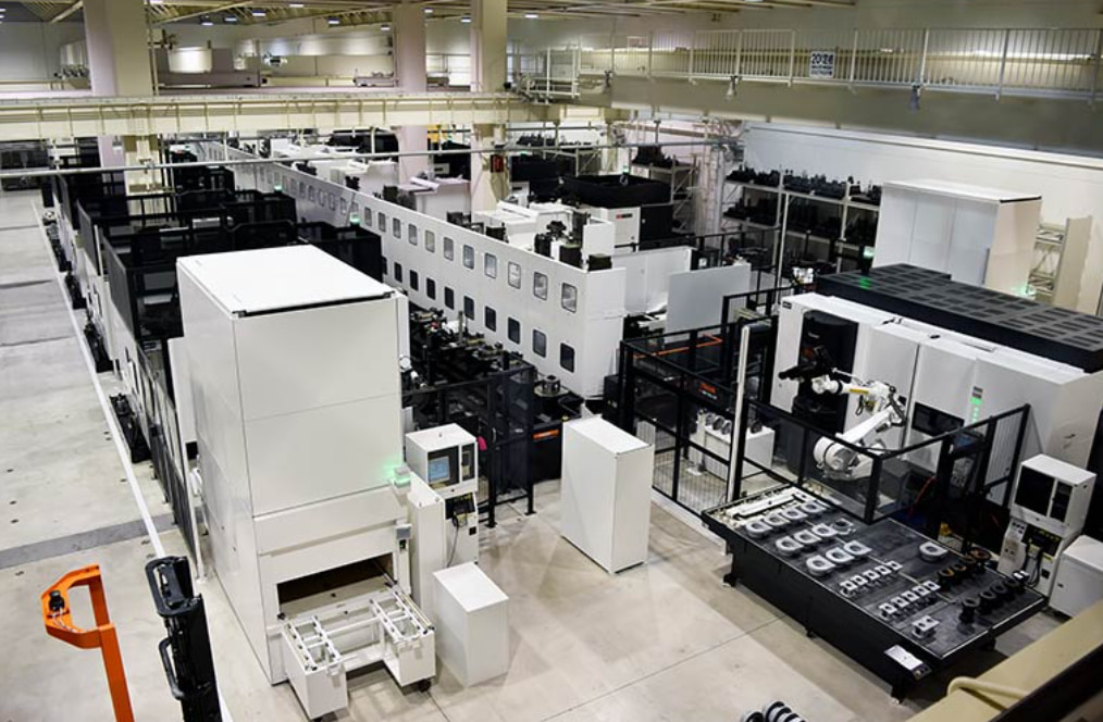
This refers to MCs used in production lines for automotive parts and similar applications. In standard MCs, the table side is often driven, but in line-compatible MCs, the mainstream type keeps the table fixed while the column side moves front-back, left-right, and up-down. This is also called the column-traverse type.
It offers excellent chip handling and good accessibility to the workpiece. Another feature is that workpieces can be easily transferred between process steps.
Source: "Hajimete no Kousaku Kikai"
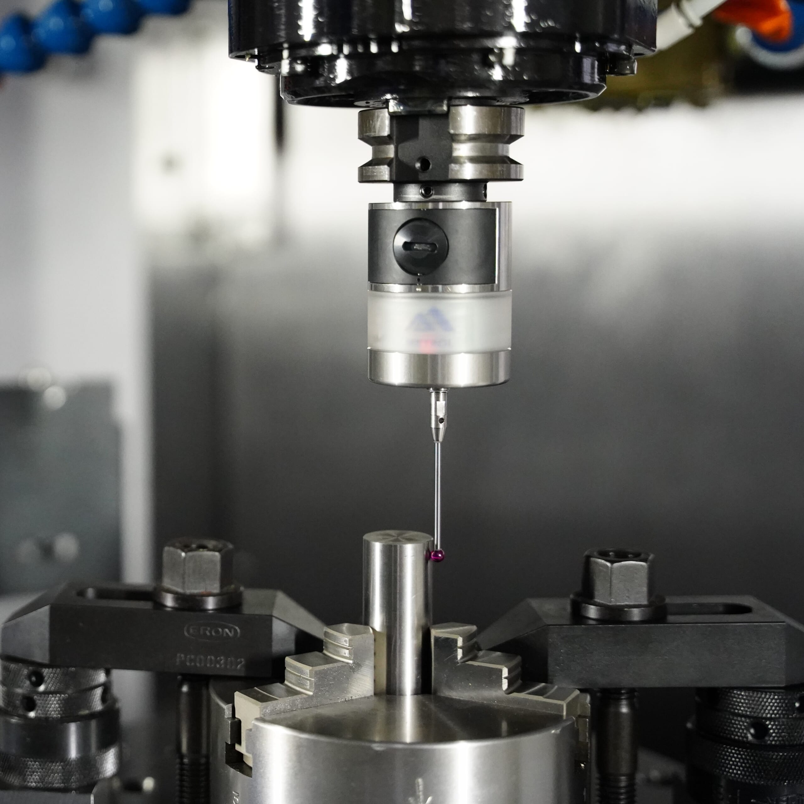
Automated workpiece centering and positioning
- Touch probe -
A contact/touch sensor for on-machine measurement that improves the efficiency of setup work
Click here ›Sensor Implementation Examples for Machining Centers
Shank adhesion confirmation realizes ultra-precise machining
We were consulted by the ATC design engineer of a machine tool manufacturer that produces machining centers regarding verification of shank contact.
By installing an air micro sensor in the tool changer of a CNC machining center, a 10 μm gap caused by chips trapped between the shank and the tool holder was detected.
Stably detected an uplift of the jig and workpiece of the CNC machine tool without contact.
Here we introduce an example of stable non-contact detection of lift-up between a fixture and a workpiece on a CNC machine tool. During cutting, chips became trapped and caused lift-up, leading to machining defects.
Air sensors made by other companies lacked sufficient accuracy and could not stably detect 10 μm lift-up. However, Metrol’s air micro sensor achieves this with an accuracy of ±0.5 μm. It can be installed inside the machine, shortens the air piping, improves response speed to 0.8 seconds, and significantly enhances productivity.
Related Articles
Detection of tool wear by CNC machining center has realized the improvement of the machining accuracy
Tool length is constantly changing in the harsh operating environment of CNC machine tools, where coolant and chips scatter and factors such as cutting wear, day-night temperature differences, and machine thermal displacement are always present.
Metrol’s “Tool Setter” feeds back the tool length value to the NC, enabling detection and compensation of tool wear with 1 μm accuracy.
This eliminates the need for skilled work such as trial cutting, measurement, and NC input, greatly improving machine utilization.