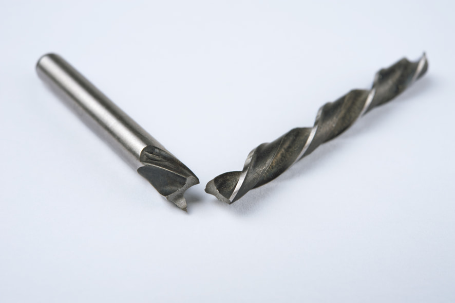
What Are Cutting Tools? An Easy-to-Understand Guide to Their Types and Features
Source: "Hajimete no Kousaku Kikai"
Key Points
- Precisely machines metal materials and more
- Hardness and toughness are the fundamental properties
- Cemented carbide tools are the most widely used
Table of Contents
What Are Cutting Tools?
Cutting tools are a general term for tools used to machine materials such as metals.
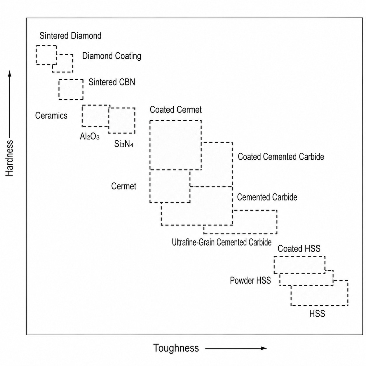
The two primary characteristics required of cutting tools are (1) hardness and (2) toughness. A cutting tool mounted on a machine tool removes material by being pressed against a workpiece fixed to the same machine. Therefore, the cutting tool material must be significantly harder than the workpiece material.
In addition, cutting tools experience significant impact at the moment they contact the workpiece. To withstand this impact, the tool material must also possess toughness. This property is referred to as "toughness."
In addition to hardness and toughness, cutting tools require various other properties. A large amount of heat is generated when the tool cuts material. Therefore, cutting tools must maintain hardness at high temperatures and also have high thermal conductivity to dissipate heat effectively. Furthermore, when the tool separates from the material, it is rapidly cooled by air exposure. Because heating and cooling repeat continuously during machining, heat resistance and resistance to sudden temperature changes are also essential.
Types of Cutting Tools
There are various types of machining processes, including turning, drilling, and milling. Accordingly, a wide variety of cutting tools are used.
1. Insert Tips
An insert tip is a replaceable cutting edge attached to a cutting tool designed for interchangeable inserts. It can be easily fastened to the tool body using screws and can be replaced quickly when worn.
Insert tips are used in turning tools, face milling cutters, indexable drills, and end mills. Cutting tools that use replaceable inserts are also called "insert-type cutting tools," "indexable tools," or "replaceable-tip tools."
Each part of an insert tip has a specific name. The surface along which chips flow during cutting is called the "rake face." The surface perpendicular to the rake face is called the "flank face," and the edge where the rake face and flank face intersect is called the "cutting edge."
The angle at which the cutting edge penetrates the material is called the "rake angle." Generally, a larger rake angle provides better cutting performance.
The angle formed between the tool feed direction and the flank face is called the "clearance angle." This angle prevents the flank face from contacting the material. In general, a smaller clearance angle increases the likelihood of contact and friction between the flank face and the material.
Conversely, a larger clearance angle reduces friction on the flank face, but it also makes the cutting edge sharper. While this improves cutting performance, it also increases the risk of chipping. Insert tips with clearance angles of approximately 5 to 10 degrees are commonly used.
There are two main types of insert tips: "positive inserts," which have a clearance angle, and "negative inserts," which have a 0-degree clearance angle. Positive inserts provide superior cutting performance but can only be used on one side. Negative inserts experience more flank wear due to the lack of clearance angle, but both sides can be used as cutting edges, making them more economical.
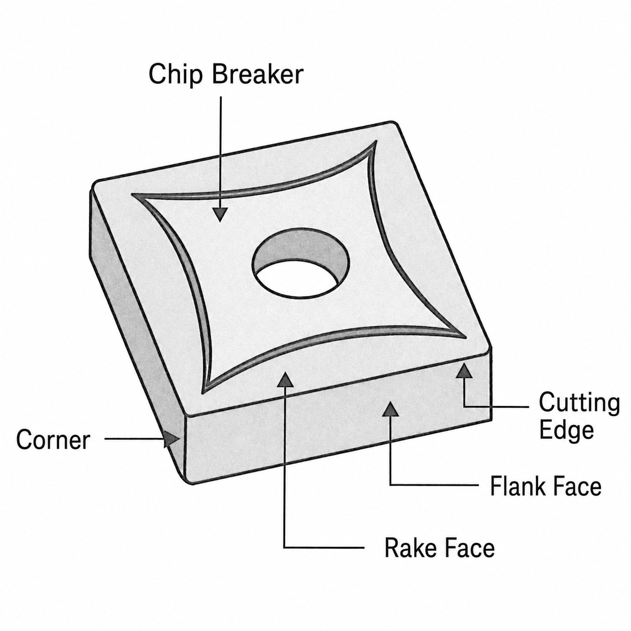
The tip area of the rake face is called the "corner" or "nose." This area is rounded, and the radius of the curvature is referred to as the "corner radius," "corner R," "nose radius," or "nose R." The "R" stands for "Radius."
In general, a larger corner radius increases cutting edge strength but reduces sharpness and cutting ability. Conversely, a smaller corner radius improves cutting performance but increases the likelihood of chipping because the edge becomes sharper.
In addition, the rake face of insert tips is designed with grooves or protrusions for chip control. These features are called "chip breakers." Here, "chip" refers to cutting chips, while "breaker" means to break or divide them. The term "chip" can refer either to the insert tip itself or to cutting chips, so attention to context is important.
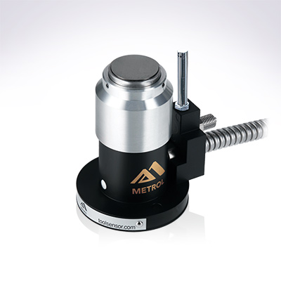
Automates originating of cutting tools
- Tool Setter -
Tool length and chips are monitored to prevent machining defects due to wear and thermal displacement
Click here ›2. Turning Tools
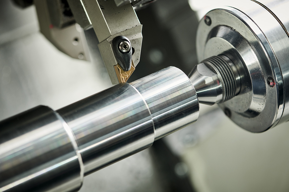
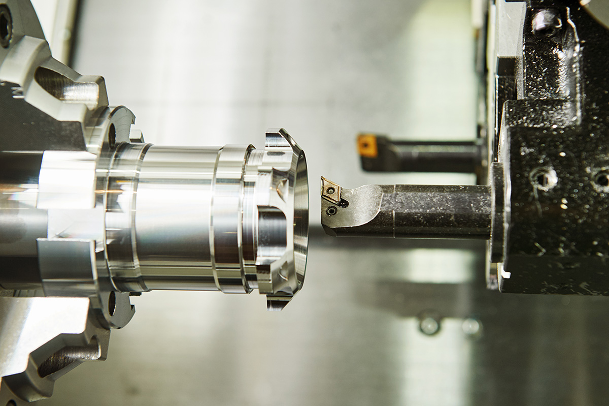
A turning tool is a tool used in turning operations. It is mounted on a lathe and used to machine cylindrical workpieces.
A turning tool consists of a cutting section that holds the insert tip and a holder called a "shank" that secures the cutting edge. The entire assembly, including the cutting section and shank, is referred to as the "body."
Turning tools are broadly classified into three types: (1) solid tools, (2) brazed-tip tools, and (3) clamp-type tools. Solid tools use the entire body as the cutting portion.
A brazed-tip tool is a type of turning tool in which the insert tip is brazed onto the body. Because a filler metal called brazing alloy is used during the joining process, it is also called a "brazed tool."
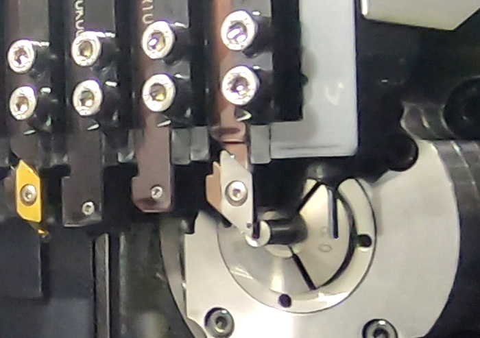
A clamp-type tool secures the insert tip using screws or similar fastening methods. Since worn inserts can be replaced easily, these tools are highly practical.
The Japanese Industrial Standards (JIS) define 32 types of turning tools according to machining applications. These include boring tools, threading tools, and parting tools used to cut off the workpiece after machining. Different tool shapes must be selected depending on the machining operation.
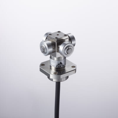
Tool Wear & Thermal Compensation
- Tool Setter -
Performs wear, chipping, and thermal displacement compensation, contributing to maintaining the constant machining precision of the machine tool
Click here ›3. Drills
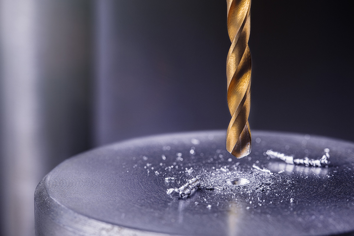
A drill is a tool used for drilling operations. Since electric drills are also commonly used in DIY work, the role of a drill is relatively easy to understand. In metalworking, drilling accounts for a large proportion of machining operations, making drills widely used in manufacturing environments.
Drills are classified in various ways based on material, structure, flute geometry, shank shape, and length. Structurally, there are three main types: solid drills with an integrated body and shank, indexable drills with replaceable insert tips, and exchangeable-head drills with replaceable cutting heads.
Based on flute geometry, drills include twist drills with helical flutes and straight drills without flute twist. Based on shank shape, there are straight shank drills with cylindrical shanks and taper shank drills with tapered shanks.
The point angle of a drill affects the cutting resistance known as thrust resistance. Thrust resistance refers to the force acting opposite to the drill feed direction. A larger point angle increases strength and enables stable machining of hard materials, but it also increases thrust resistance. Conversely, a sharper point angle reduces thrust resistance and is suitable for machining softer materials such as aluminum alloys. Flat drills with a 180-degree flat point are also available.
In drilling operations, chip evacuation becomes more difficult as holes become narrower and deeper. To remove chips effectively, machining is often performed using "step feed," where the drill is periodically retracted from the hole and then reinserted.
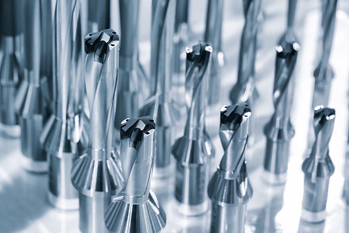
To improve chip evacuation efficiency, internally cooled drills are increasingly used. Normally, coolant is supplied externally through hoses, but internally cooled drills deliver coolant directly through the drill tip, enabling effective coolant supply even in deep-hole machining.
Special drills called gun drills are used when drilling holes that are dozens of times deeper than the drill diameter.
4. Milling Cutters
Milling cutters are tools used to machine flat surfaces and grooves in plates and block materials.
A key feature of milling cutters is that they have multiple cutting edges arranged around the circumference. Tools of this type are called multi-edge tools. As the milling cutter rotates and machines the workpiece fixed to the machine table, each cutting edge alternates between cutting and non-cutting periods. This process is called "interrupted cutting."
Significant impact occurs each time a cutting edge contacts the workpiece. Since milling cutters have multiple edges, this impact is repeated continuously. Therefore, multi-edge tools such as milling cutters require high toughness to withstand repeated impacts.
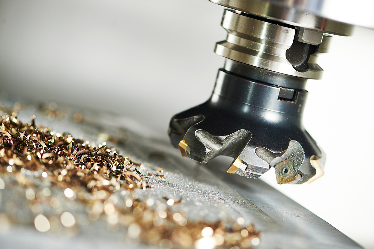
In contrast, turning tools used in turning operations have only one cutting edge and are called single-edge tools. In turning, the workpiece rotates, so the cutting edge contacts the workpiece only once at the start of machining and then remains in continuous contact. This process is called "continuous cutting."
There are various types of milling cutters, including face mills and plain milling cutters. Face mills are used for wide-area surface machining of plates and blocks, while plain milling cutters are used for machining flat surfaces and grooves.
5. End Mills
An end mill is also a type of milling cutter used for machining grooves, side surfaces, and contours in plates and blocks. The name comes from the fact that it has cutting edges on both the outer circumference and the end face (bottom). A key feature is its ability to machine various shapes with a single tool.
Structurally, end mills include solid end mills with integrated cutting sections and shanks, as well as indexable end mills that use replaceable insert tips.
Based on cutting edge shape, end mills are classified into three types: (1) square end mills, (2) radius end mills, and (3) ball end mills.
Square end mills have flat bottom edges and are mainly used for machining grooves and side surfaces. Radius end mills have rounded corners on the bottom edge. Ball end mills have spherical cutting ends and are effective for machining curved surfaces.
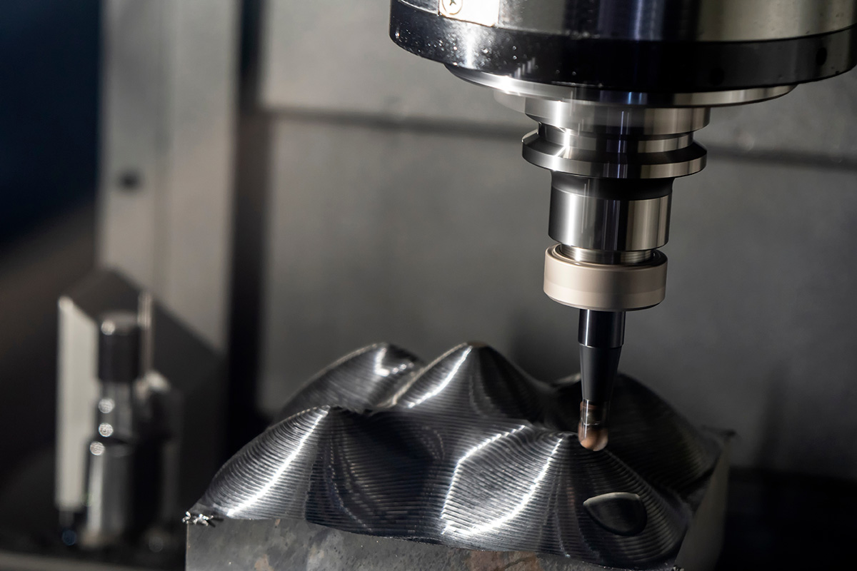
Other types include roughing end mills with wavy peripheral cutting edges and tapered end mills with peripheral edges that narrow toward the tip.
In recent years, specially shaped end mills with a large radius on the peripheral cutting edge have also appeared. Although dedicated CAM software is required, their large peripheral radius enables more efficient machining than standard ball end mills. These are called "form tools" or "barrel tools" because the cutting edge resembles the shape of a barrel.
6. Reamers and Boring Bars
Reamers and boring bars are tools used to finish pilot holes drilled beforehand to precise dimensions and shapes, while also smoothing the inner surface of the hole.
Reamers are generally used for holes up to approximately 20 mm in diameter. For larger holes, boring bars are used.
When machining deep holes with a boring bar, the tool overhang becomes longer. A longer overhang can cause tool vibration during machining, which may reduce hole accuracy. Therefore, boring bars require features that suppress this type of vibration.
7. Taps and Dies
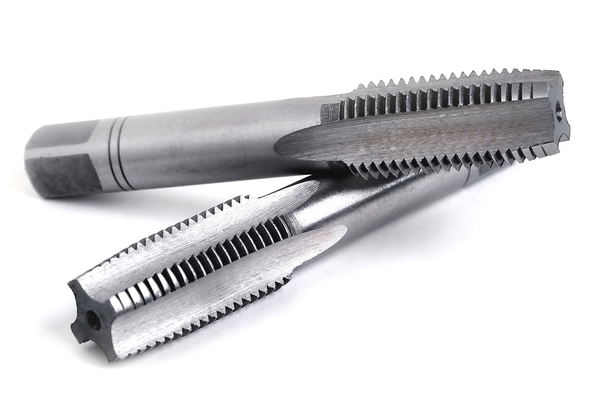
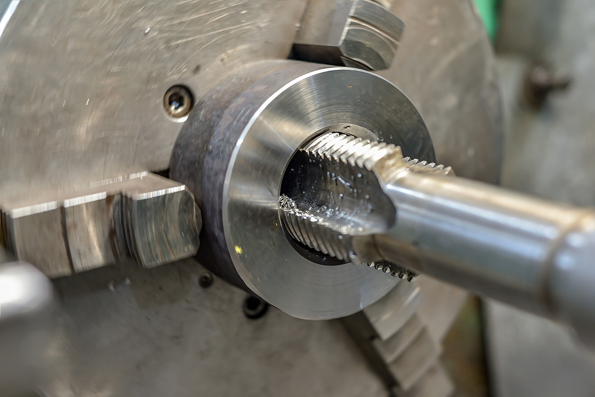
Taps and dies are tools used to cut threads into pilot holes drilled beforehand. A tap is used to create an internal thread, or "female thread," inside a hole. A die is used to create an external thread, or "male thread," on the outside of a workpiece. It may be easier to think of male threads as bolts and female threads as nuts.
Taps are broadly classified into two types: cutting taps, which generate and discharge chips, and forming taps, which create threads without producing chips.
Types of cutting taps include spiral taps, hand taps, and point taps. Spiral taps have twisted flutes that guide chips upward along the spiral. Hand taps have straight flutes and can be used for both through holes and blind holes. Point taps push chips forward, making them suitable for through-hole machining but not for blind holes.
Dies are also available in cutting and forming types, but thread manufacturing often uses forming dies, which do not produce chips.
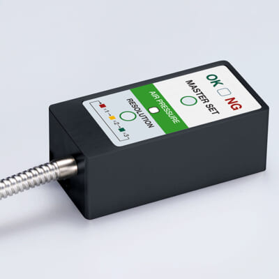
High-precision seating confirmation of workpiece and jig
- Air Gap Sensor -
You can check not only "presence/absence" but also "adhesion (gap)" at the same time with a repeatability of ±0.5 μm.
Click here ›Tool Materials
Although there are countless materials in the world, it is said that only around ten types are commonly used for cutting tools.
1. PCD
PCD stands for "Poly-Crystalline Diamond" and refers to sintered diamond material.
PCD is manufactured by adding cobalt, which acts as a binder, to diamond powder and then sintering the mixture. It is the hardest material used in cutting tools and performs exceptionally well when machining non-ferrous materials such as aluminum alloys and copper alloys.
However, PCD is not suitable for machining ferrous materials. Diamond consists of carbon atoms, and carbon has high chemical affinity with iron-based materials. As a result, machining ferrous materials with PCD tools causes severe wear and significantly shortens tool life.
2. CBN
CBN stands for "Cubic Boron Nitride." It is a synthetic material composed of boron and nitrogen and was developed by General Electric (GE) in the United States in 1957.
CBN is second only to diamond in hardness and also offers excellent heat resistance. Unlike diamond, it has no chemical affinity with carbon, making it suitable for machining ferrous materials containing carbon. It is primarily used for machining hardened steel, cast iron, and heat-resistant alloys such as nickel-based superalloys.
3. Ceramics
Although ceramics are often associated with pottery and similar products, they are also used as cutting tool materials.
Ceramics are characterized by their ability to maintain hardness at high temperatures and their low chemical affinity with metals.
Ceramics used for cutting tools are broadly classified into two categories: (1) alumina-based ceramics and (2) silicon nitride-based ceramics. Alumina-based ceramics are further divided into "white ceramics," primarily composed of aluminum oxide, and "black ceramics," which contain titanium carbide in addition to aluminum oxide. Black ceramics offer greater toughness than white ceramics, and both are suitable for finishing cast iron.
There are also alumina-based materials reinforced with needle-shaped silicon carbide crystals called whiskers, which perform well in machining heat-resistant alloys.
Silicon nitride-based ceramics are divided into those primarily composed of silicon nitride and "Sialon," which contains aluminum oxide in addition to silicon nitride. Silicon nitride types maintain toughness even at high temperatures and are suitable for milling operations, while Sialon is effective for machining heat-resistant alloys.
4. Cermets
Cermets are materials made by sintering powders such as titanium carbide, titanium nitride, tantalum carbide, and tantalum nitride together with binders such as nickel or cobalt. Because they combine the properties of ceramics and metals, the name "Cermet" is derived from "Ceramic" and "Metal."
One characteristic of cermets is that they do not contain tungsten, the primary component of cemented carbide. Tungsten has high affinity with iron and tends to alloy easily with it. Since cermets do not contain tungsten, they are widely used for machining ferrous materials and cast iron.
5. Cemented Carbide
Cemented carbide is a material that offers a well-balanced combination of hardness and toughness required for cutting tools. Carbide tools made from this material are the most widely used tools in metalworking environments.
The primary component of cemented carbide is tungsten carbide, which is produced by sintering tungsten carbide powder together with cobalt as a binder.
Under JIS standards, cemented carbide for cutting tools is classified into six categories: "P," "M," "K," "N," "S," and "H." P is used for steel materials, M for stainless steel, K for cast iron, N for aluminum, S for heat-resistant alloys such as titanium alloys, and H for hardened steel.
The toughness of cemented carbide also changes depending on the amount of binder content. Increasing the binder improves toughness but reduces hardness. Therefore, selecting the optimal carbide grade according to the characteristics of the workpiece is important.
Cemented carbide was first commercialized in 1926 by the German company Krupp under the trademark "Widia," which means "diamond-like."
6. Ultra-Fine Grain Cemented Carbide
Ultra-fine grain cemented carbide is a carbide alloy made using extremely small tungsten carbide particles. Under JIS standards, materials with an average particle size of 1 μm or less are defined as ultra-fine grain cemented carbide. One micrometer equals one-thousandth of a millimeter.
Reducing the size of tungsten carbide particles improves toughness compared with standard cemented carbide. As a result, ultra-fine grain carbide is used for milling cutters subjected to interrupted cutting and for small-diameter tools that are thin and prone to breakage.
7. High-Speed Steel
High-speed steel (HSS) is short for high-speed tool steel. It is broadly divided into tungsten-based and molybdenum-based types. Generally, tungsten-based HSS offers superior hardness, while molybdenum-based HSS provides better toughness. Adding cobalt further increases hardness in both types. HSS containing cobalt is called "cobalt HSS."
Although HSS is less hard than cemented carbide, it offers excellent toughness and impact resistance. However, it is vulnerable to heat and rapidly loses hardness above 600°C. Therefore, it is suitable for machining applications where cutting temperatures remain relatively low and toughness is required. For example, taps used for internal threading require toughness to prevent breakage during machining, so HSS is often used for taps.
HSS is often produced by melting the material in a furnace and casting it into molds, similar to ordinary steel materials. However, it can also be manufactured by sintering HSS powder under high temperature and pressure. This material is called "powder HSS" and offers both higher hardness and greater toughness than conventional HSS.
8. Coatings
Coated tools are tools whose substrate surfaces, such as cemented carbide, HSS, or cermet, are covered with a thin film. The primary purpose is to enhance or complement the properties of the substrate material.
Different coating types provide various properties such as hardness, toughness, heat resistance, and anti-adhesion performance. Coatings include "single-layer coatings" made from one material and "multi-layer coatings" made from two or more materials.
Representative coatings include (1) diamond-like carbon (DLC), (2) titanium nitride (TiN), (3) titanium carbonitride (TiCN), (4) titanium aluminum nitride (TiAlN), and (5) aluminum oxide (Al2O3).
There are two main coating methods: Chemical Vapor Deposition (CVD), which forms coatings through chemical reactions, and Physical Vapor Deposition (PVD), which forms coatings by bombarding the substrate surface with metal ions generated through processes such as electrical discharge.
Source: "Hajimete no Kousaku Kikai"
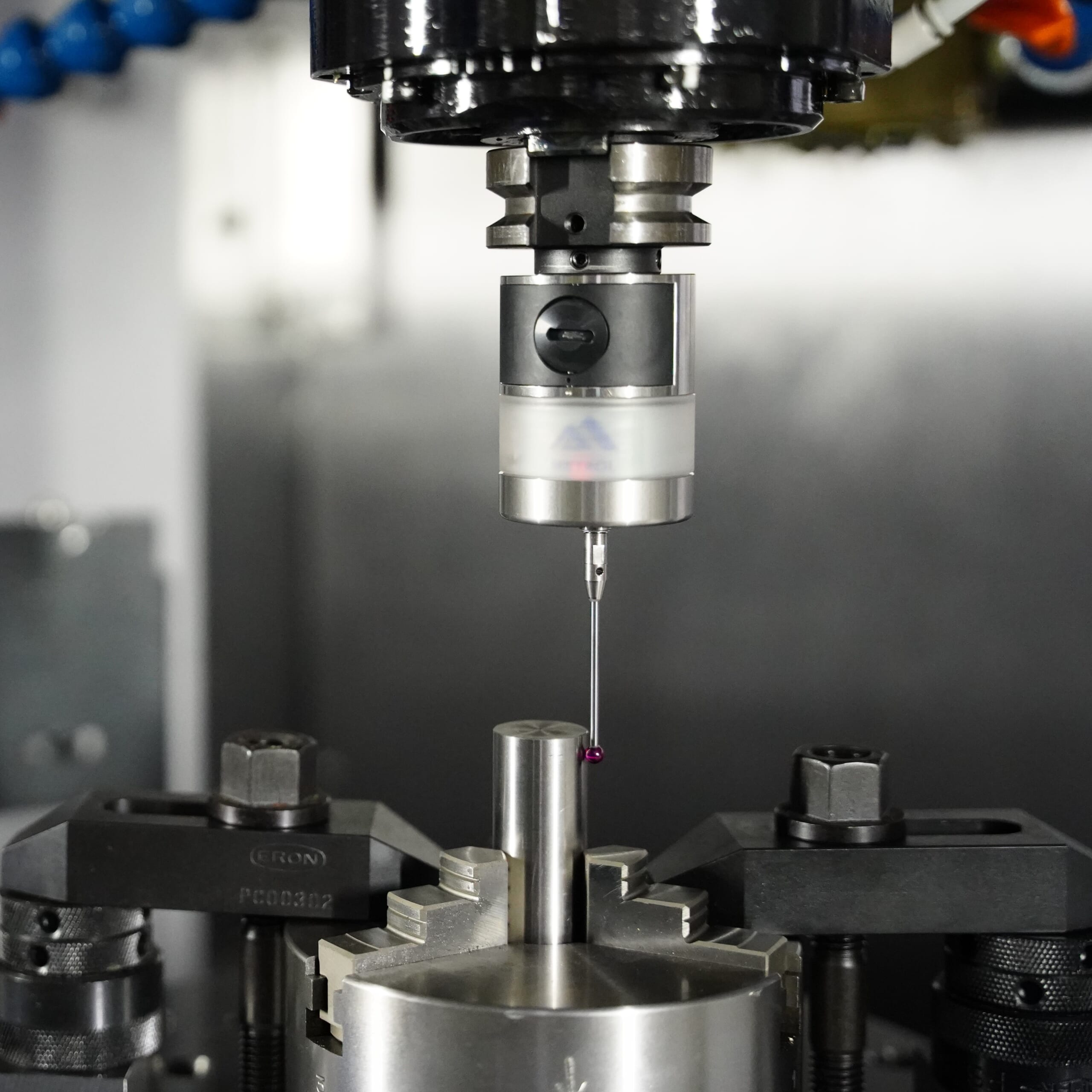
Automated workpiece centering and positioning
- Touch probe -
A contact/touch sensor for on-machine measurement that improves the efficiency of setup work
Click here ›Sensor Implementation Case Studies
Detection of tool wear by CNC machining center has realized the improvement of the machining accuracy
This is a precision machining manufacturer producing precision components for a major aerospace manufacturer.
The person in charge of the cutting department consulted us regarding tool wear detection during machining center operations.
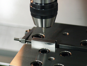
[CNC Lathe Users MUST SEE! ] How to Reduce L-dimension defects in Machined Parts to Zero?
- When the workpiece is clamped, chips can lift the bar material and cause machining defects…
- Once a machining defect occurs, large numbers of defective parts may be produced continuously…
- After defective products occur, full inspection for pass/fail sorting becomes extremely difficult…
- Measurement errors can vary depending on the inspector…
In fact, Metrol has received the following issues from customers.
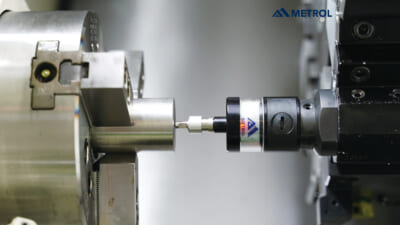
[Video]
【A must-see for CNC Users】Automate Tool Measurement High-PrecisionTool Setter
Related Articles
Cutting Tool Breakage Basics: Setting Machining Conditions and Solving Common Problems
Anyone involved in machining has likely experienced "tool breakage" at least once. Tool breakage refers to the phenomenon in which a cutting tool suddenly breaks or deforms during machining.
Many people think, "Since tools are consumables, breakage is unavoidable."
However, understanding why breakage occurs can reduce product losses and tool consumption caused by tool failure.
This article clearly explains the main causes of tool breakage and the countermeasures used to prevent it.